

HZSDR1006000-A01 · 100 MHz – 6 GHz · Dual RF Output SDR RF Source Module Manufacturer for OEM Integration
Designed and manufactured by CorelixRF for embedded RF platforms, waveform development, and engineering-driven system integration. The HZSDR1006000-A01 combines dual independent RF outputs, RS422 control, compact board-level structure, and scalable project support from prototype to volume production.
Why Buy Directly From
the Manufacturer
This is not a generic catalog listing. CorelixRF designs, manufactures, tests, and supports RF hardware in-house. For customers evaluating SDR source modules for OEM integration, that means faster technical alignment, clearer communication, and more practical support during sample review, interface discussion, and project ramp-up.


Where This Module Fits
The HZSDR1006000-A01 is best suited for projects that need compact dual-channel RF source capability, board-level integration, and practical control architecture for engineering development.
Embedded RF System Prototyping
For customers building compact RF subsystems, the module supports early-stage design verification where board size, supply range, and controllable RF output matter.
Dual-Channel Signal Development
Suitable for applications requiring dual independent RF outputs for signal generation, verification, or controlled waveform-related development tasks.
OEM RF Equipment Integration
Designed for equipment manufacturers that need a compact SDR-based source module to integrate into custom platforms rather than deploy as a bench-top instrument.

Laboratory & Controlled Industrial RF
Applicable to controlled industrial RF environments where compact footprint, digital control, and project-specific integration are more important than traditional lab-only form factors.
Why Choose a Compact OEM SDR Source Module
Instead of a Bench-Top Signal Generator?
Easier Equipment Integration
Board-level form factor allows direct mounting inside enclosures and subsystems, eliminating the need for external test equipment in production environments.
Smaller Footprint
At 60 × 140 × 14 mm and under 200 g, the module fits where bench-top instruments cannot — inside compact platforms, mobile units, and space-constrained designs.
Direct Digital Control
RS422 serial interface enables automated, host-controlled operation without manual intervention — suitable for embedded systems and equipment-level automation.
Better Fit for System-Level Projects
Designed for OEM integration from the start, not adapted from a lab instrument. Power, mechanical, and interface architecture are built for project-level deployment.
Built for Engineering
Review & Integration
Beyond frequency coverage, this module is built around compact integration, dual-channel architecture, and practical communication structure for OEM-oriented RF projects.
Dual Independent RF Outputs
Two RF output paths support project architectures that require channel separation, flexible signal routing, or dual-path development.
Wide Frequency Coverage
100 MHz to 6 GHz frequency coverage helps reduce the need for multiple source modules across different development stages.
RS422 Communication
RS422 control supports equipment-level communication requirements where stable, structured interface control is needed.
Compact OEM Form Factor
With a compact 60 × 140 × 14 mm structure and lightweight design, the module is suited for board-level integration where space and mechanical planning matter.
Built-In Selectable Waveform Options
For engineering buyers, specifications alone are not enough. Evaluation usually depends on waveform capability, interface behavior, and expected integration consistency. This module supports upgradeable built-in waveform options, and project-specific discussion can be arranged during technical review.
Single-frequency continuous wave output. Suitable for narrowband applications and system calibration. Gain adjustable across 35 discrete levels per channel.
Linear frequency modulation chirp sweep. Available in 5 MHz, 10 MHz, 20 MHz, 70 MHz, and 100 MHz bandwidth variants for wideband swept-frequency applications.
GNSS_70M waveform option covering GPS, BeiDou, and GLONASS frequency bands. Suitable for GNSS-band signal source requirements in development and testing environments.
OFDM multi-carrier waveform options available in 5 MHz, 10 MHz, 20 MHz, 70 MHz, and 100 MHz bandwidth configurations for broadband signal generation applications.
Evaluation Support: For qualified projects, engineering communication may include waveform alignment, interface discussion, and sample-stage review. Built-in waveform options can be discussed based on project requirements and application direction.
Full Specifications
The HZSDR1006000-A01 is intended for engineering evaluation and OEM integration. In addition to core specifications, design-in review should consider mechanical space, power architecture, interface planning, and application-level signal requirements.
| RF PERFORMANCE | |
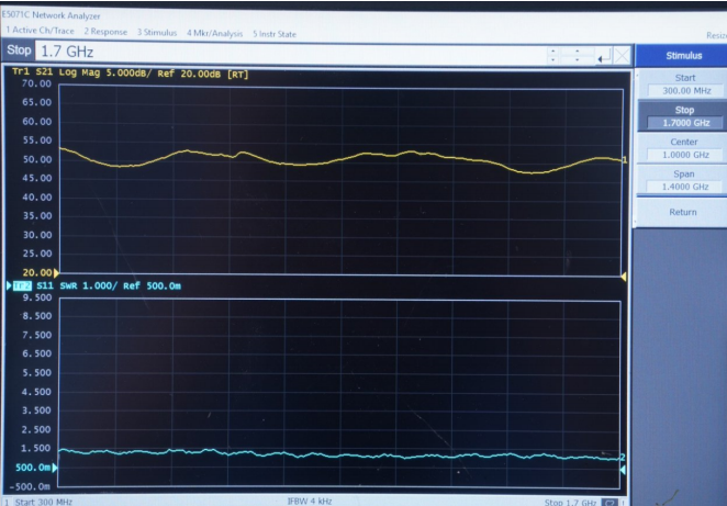
| Frequency Range | 100 MHz – 6000 MHz continuous |
| RT Bandwidth / Channel | 100 MHz max |
| Combined RT Bandwidth | 200 MHz (dual channel) |
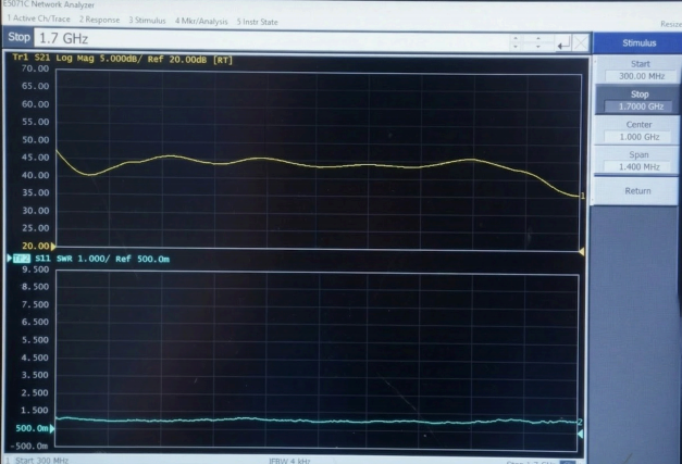
| Output Power (OFDM 20M) | >0 dBm typ. — varies by frequency |
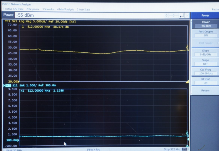
| Dynamic Range | >25 dB |
| Gain Adjustment Steps | 35 levels |
| Frequency Accuracy | <0.1 MHz typical |
| VSWR | <2.5 @2.4 GHz, typ. |
| Out-of-Band Suppression | >40 dB typical |
| Output Power Ripple | <1 dB avg — adequate cooling required |
| WAVEFORM OPTIONS | |
| Waveform Types | CW · LFM · GNSS · OFDM |
| LFM Bandwidth Options | 5M · 10M · 20M · 70M · 100M |
| OFDM Bandwidth Options | 5M · 10M · 20M · 70M · 100M |
| Protocol-Specific Options | TBS (868/915) · ELRS (868/915/2450) |
| Waveform Support | Built-in options available; scope aligned during engineering review |
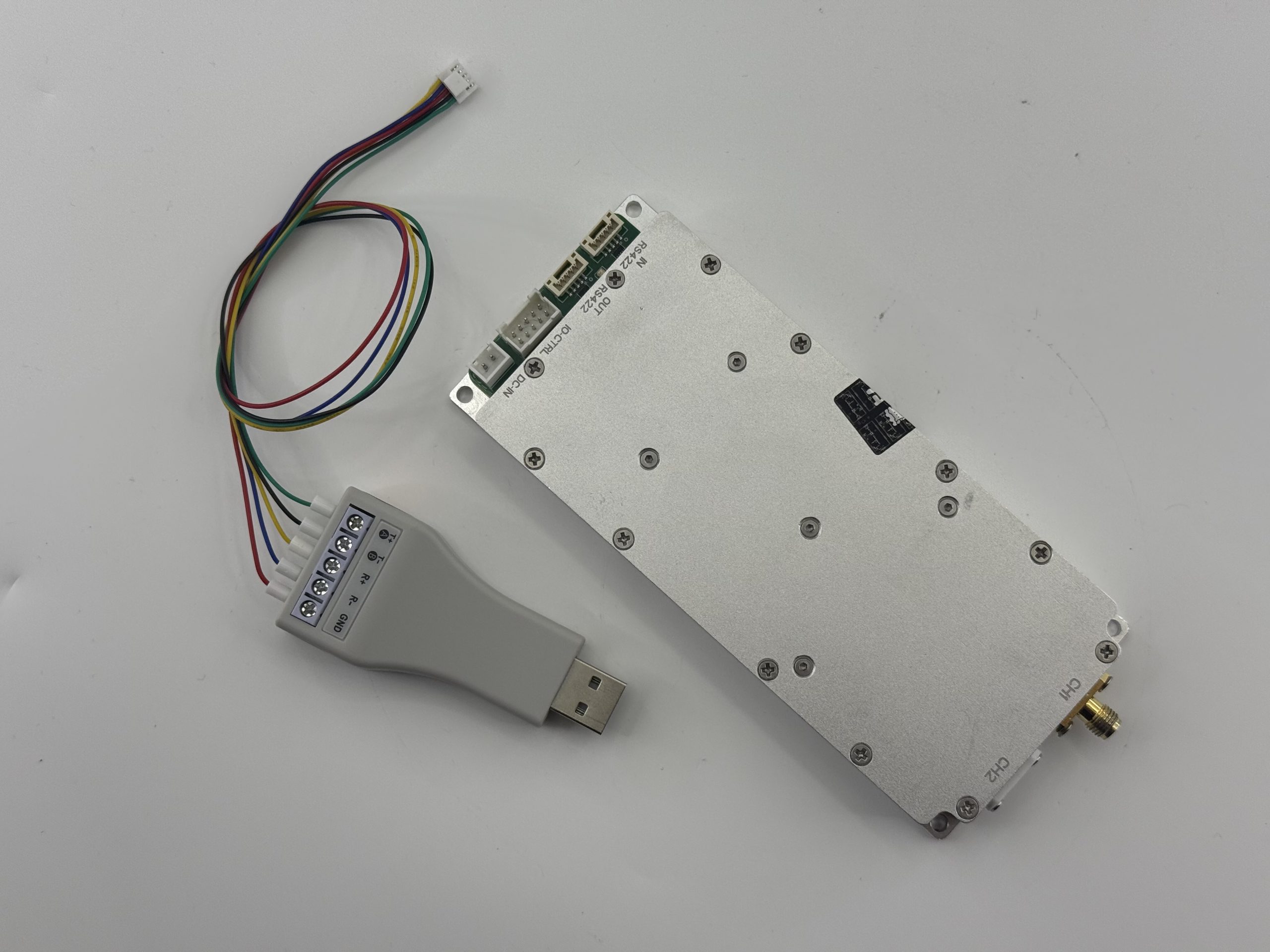
| INTERFACE / CONTROL | |
| Control Interface | RS422 serial bus |
| RF Connectors | 2× SMA — dual independent output |
| Standby Power | <5 W |
| MECHANICAL / POWER | |
| Dimensions | 60 × 140 × 14 mm |
| Weight | <200 g |
| Supply Voltage | DC 9–32 V |
| Max Current | 0.5 A @ 9 V |
| Operating Temperature | −40°C to +70°C |
Host Control System
RS422 BUS · HOST-SIDE PARAMETER SETTING
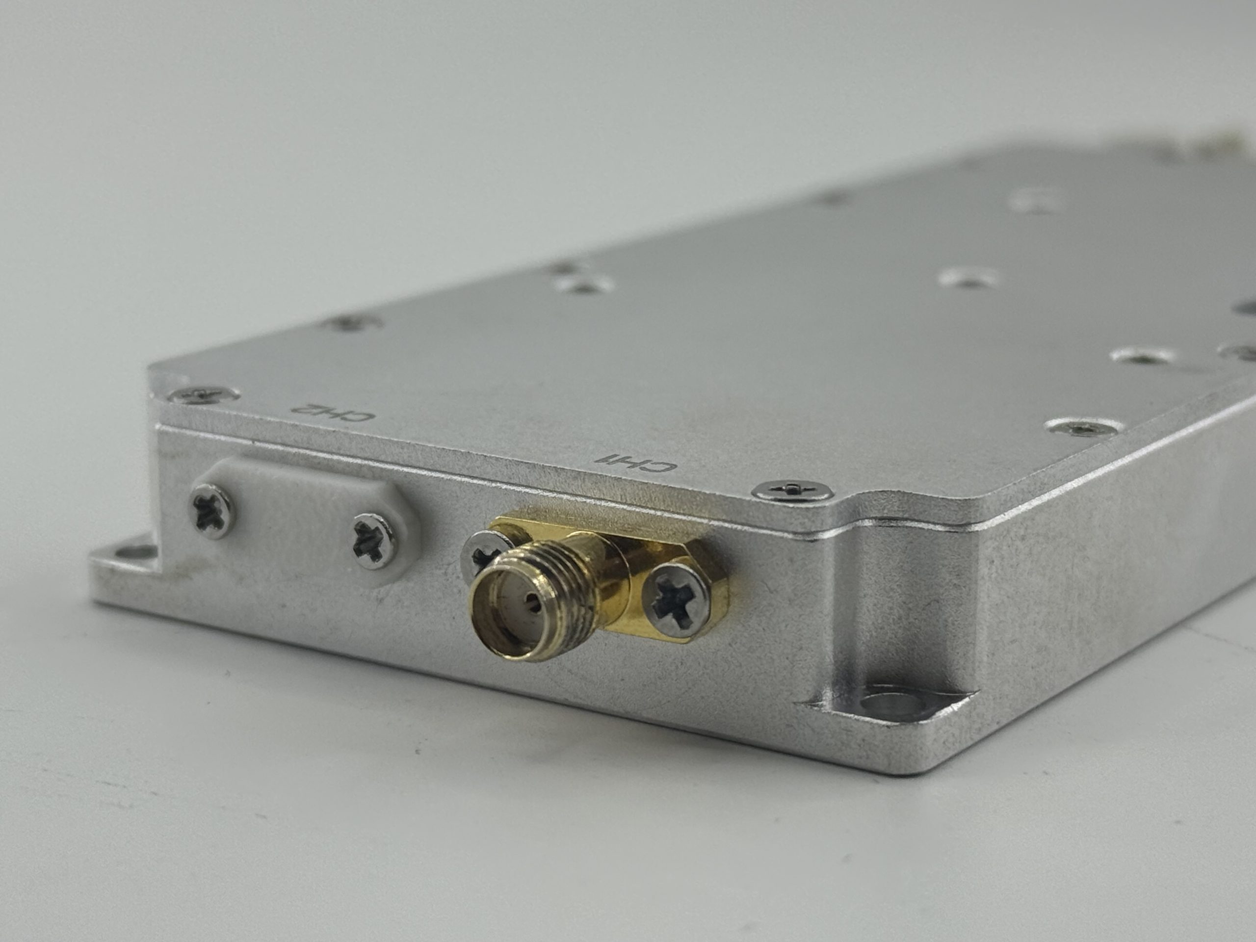
HZSDR1006000-A01 Module
DUAL CH · 100 MHz BW EACH · 9–32 VDC · <200 g
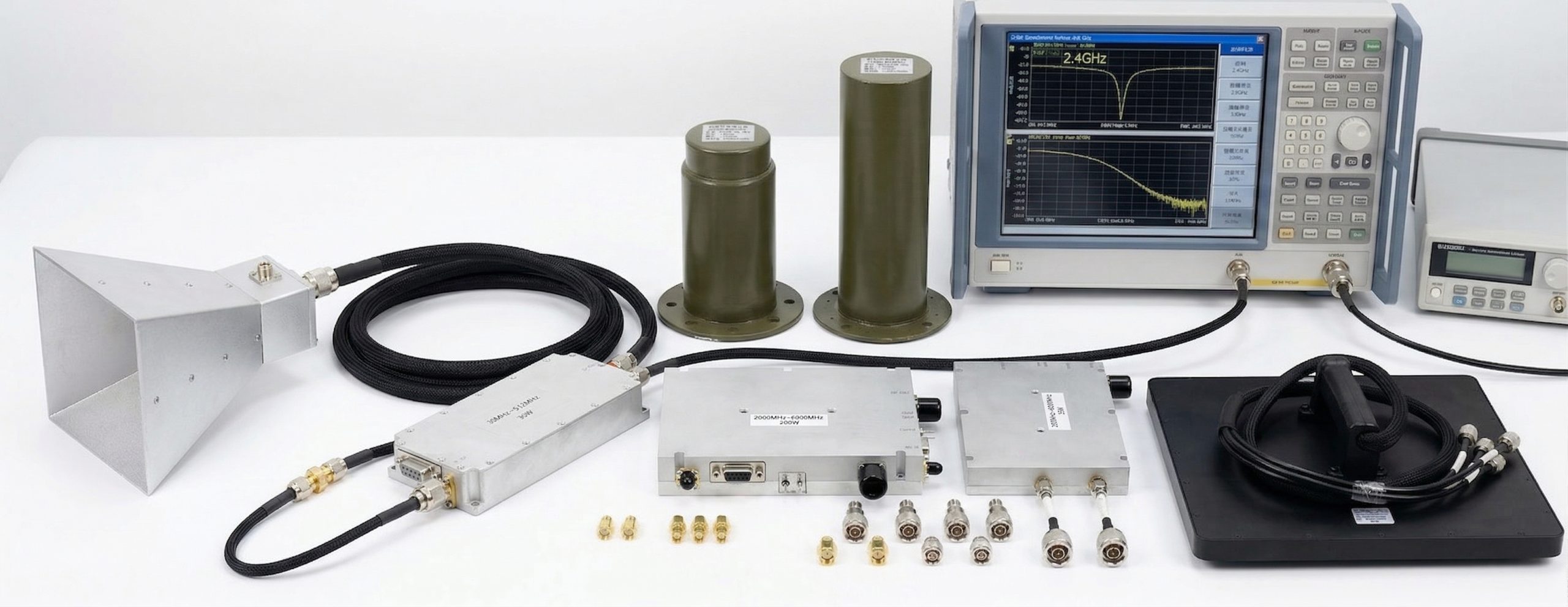
Power Amplifier
BROADBAND · APPLICATION-DEPENDENT · CorelixRF PA SERIES
Broadband Antenna
WIDEBAND · DIRECTIONAL / OMNI · CorelixRF ANT SERIES
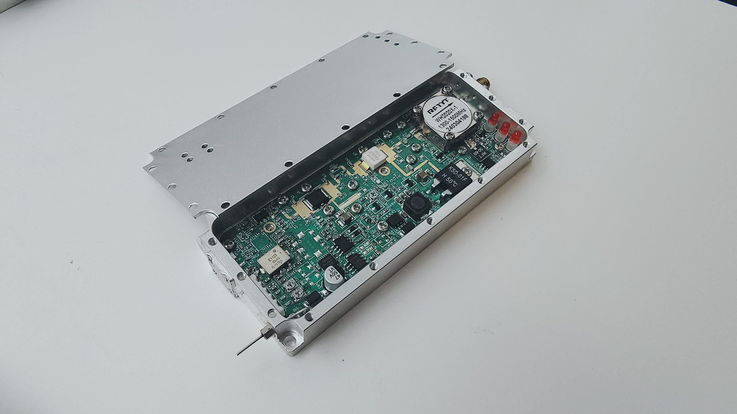
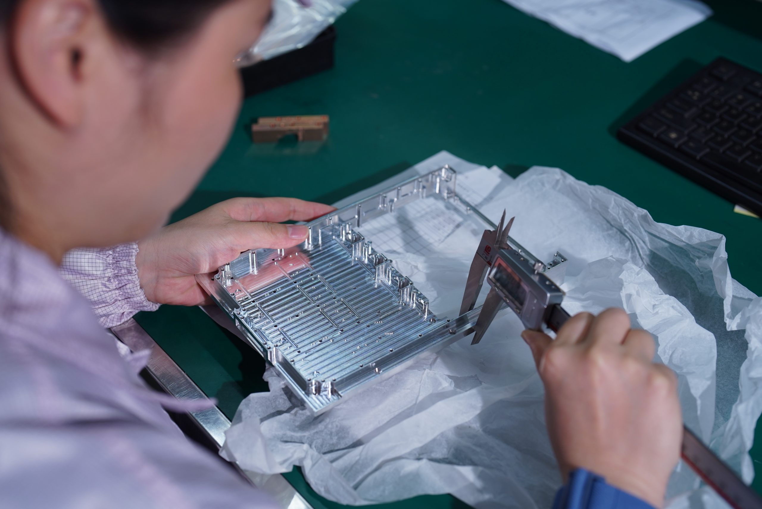
Manufacturing Evidence
Behind the Module
For OEM buyers, supplier selection is not based on appearance alone. Manufacturing consistency, communication depth, and practical support matter during qualification and scale-up. CorelixRF supports RF hardware projects with in-house manufacturing and engineering coordination.


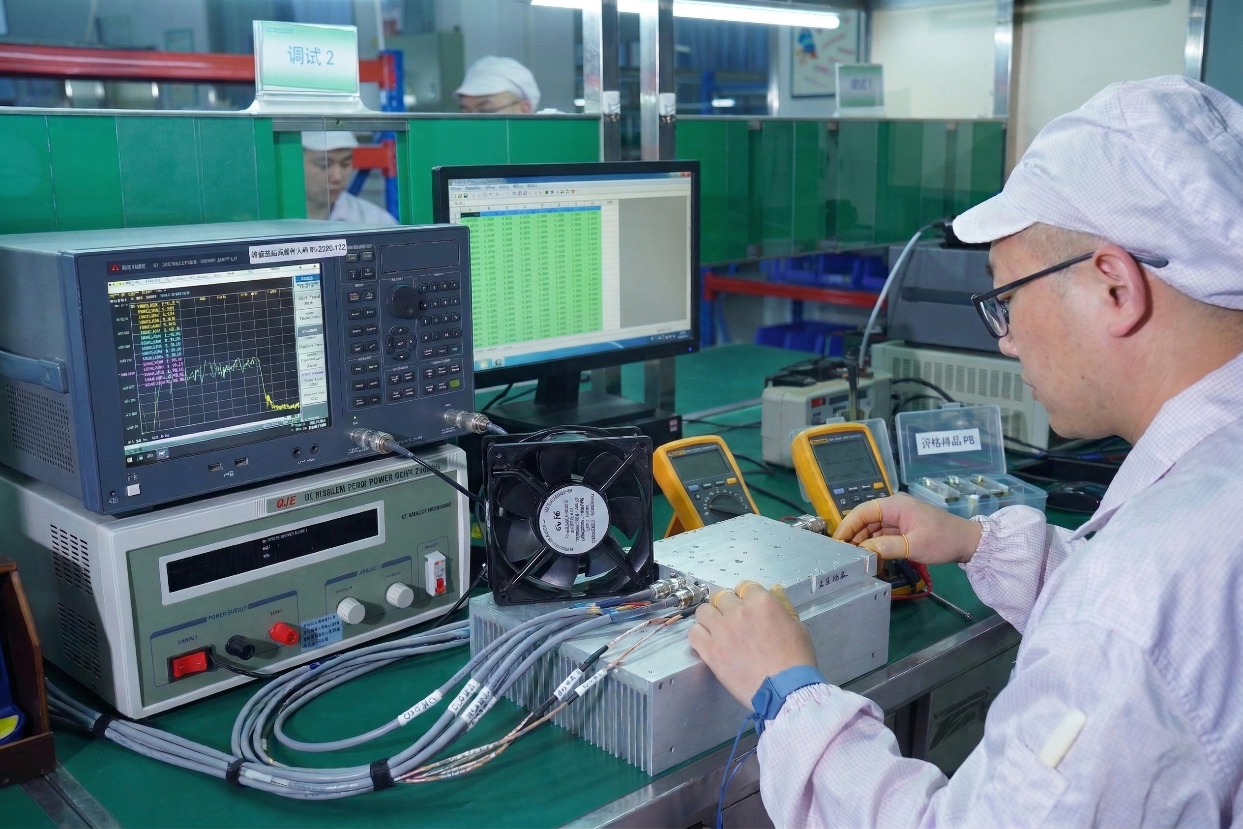
Quality and Test Process
for Project Evaluation
Each unit goes through a documented quality workflow before shipment. For project evaluation and OEM review, test communication can be aligned with the buyer's engineering concerns.
Incoming Material Control
- Critical component inspection as required
- Traceability log maintained for key parts
- Incoming inspection includes visual and instrument-based checks
- Vendor evaluation updated per batch
Assembly and Functional Verification
- Assembly-stage checks confirm module integrity
- Functional frequency verification across operating range
- Port consistency and output isolation checks
- RS422 command-response functional test
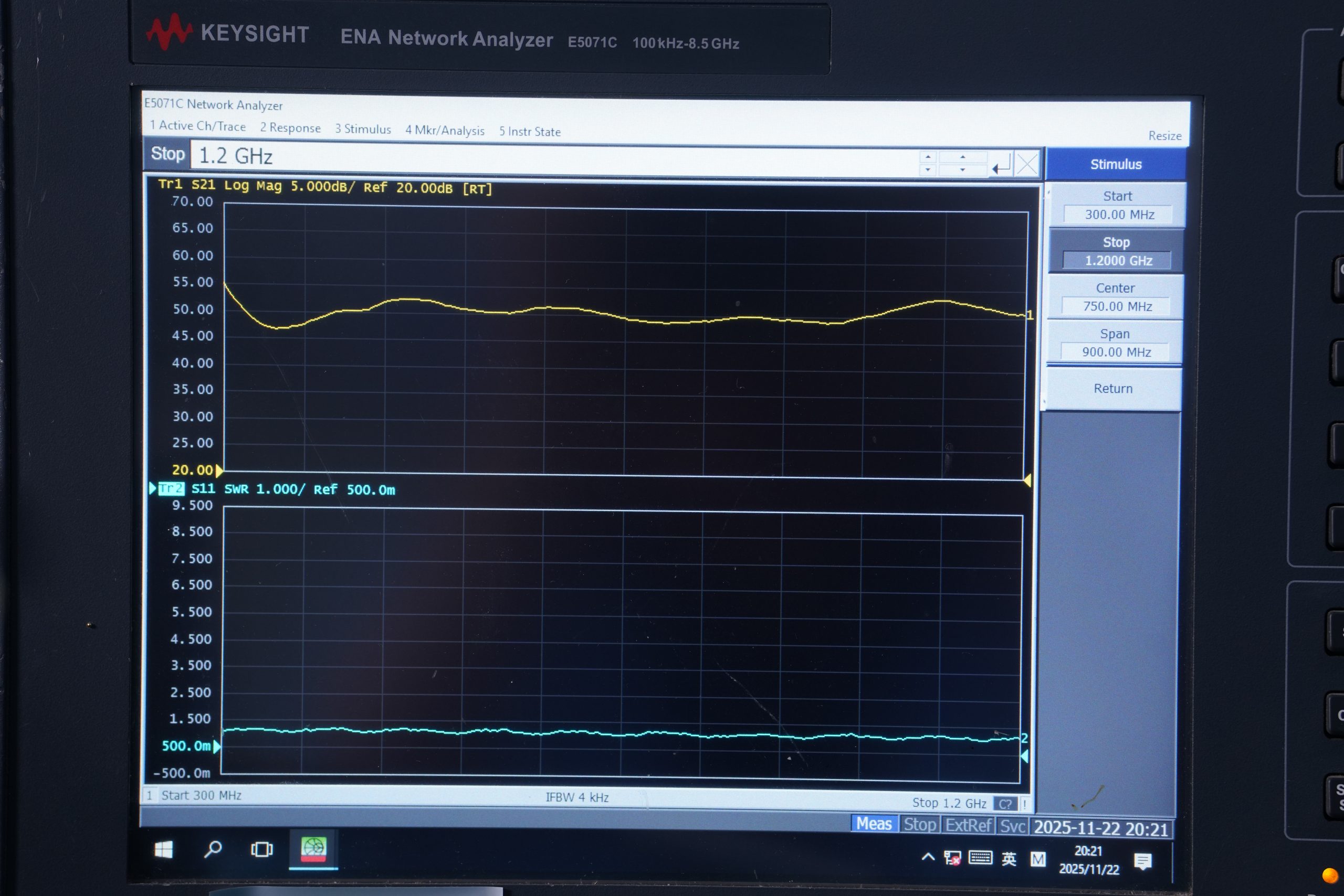
Final RF Test and Documentation
- Final RF verification at rated conditions
- Environmental validation available by project requirement
- Post-test RF performance confirmation
- Test documentation may be provided upon request
FAQ for OEM Buyers
& Engineering Teams
Is this module suitable for OEM integration rather than standalone lab use?
Yes. The HZSDR1006000-A01 is a compact SDR RF source module designed for OEM integration, embedded RF development, and project-based equipment design rather than as a traditional bench-top instrument.
Can CorelixRF support engineering communication before sample purchase?
Yes. Engineering discussion can cover application fit, interface direction, and integration-related considerations before the project moves into sample review.
What control interface does this module use?
The module uses RS422 communication, which is suitable for equipment-level control architecture in integration-oriented projects. It supports multi-module cascade on a single bus.
Can waveform options be discussed or upgraded?
Yes. The module supports upgradeable built-in waveform options. Specific waveform availability and implementation scope should be aligned during engineering review according to the intended application.
Is the module suitable for small-batch evaluation before volume rollout?
Yes. CorelixRF supports both prototype and volume programs with MOQ of 1 unit for initial evaluation.
Can unit-level quality documentation be provided?
Yes. Unit-level test documentation may be provided upon request as part of the documented three-phase quality process.
From Inquiry to Volume Production
CorelixRF supports a structured project workflow from initial inquiry through volume delivery. Each stage includes direct engineering communication.
This product page is intended for lawful industrial, laboratory, OEM, and authorized project evaluation purposes. Availability, shipment, documentation scope, and support may depend on end use, destination, and applicable compliance review requirements.
Discuss Your RF Project
With the Factory Engineering Team
If you are evaluating a dual-channel SDR RF source module for OEM integration, send us your project requirements. Our team can support application matching, interface review, and sample-stage communication for engineering-driven RF projects.

for OEM integration.