
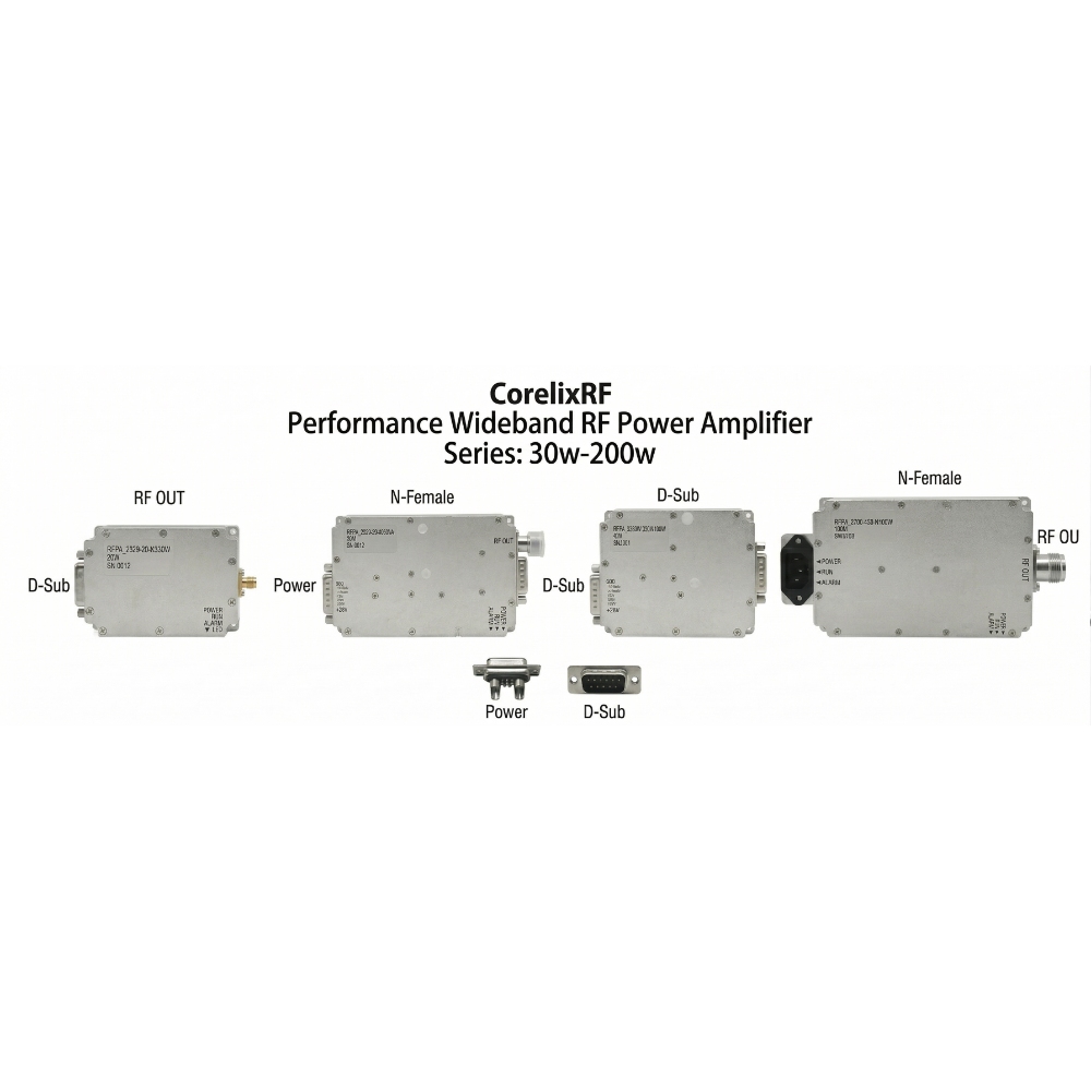
 STANDARD
RF PA Platform
STANDARD
RF PA Platform
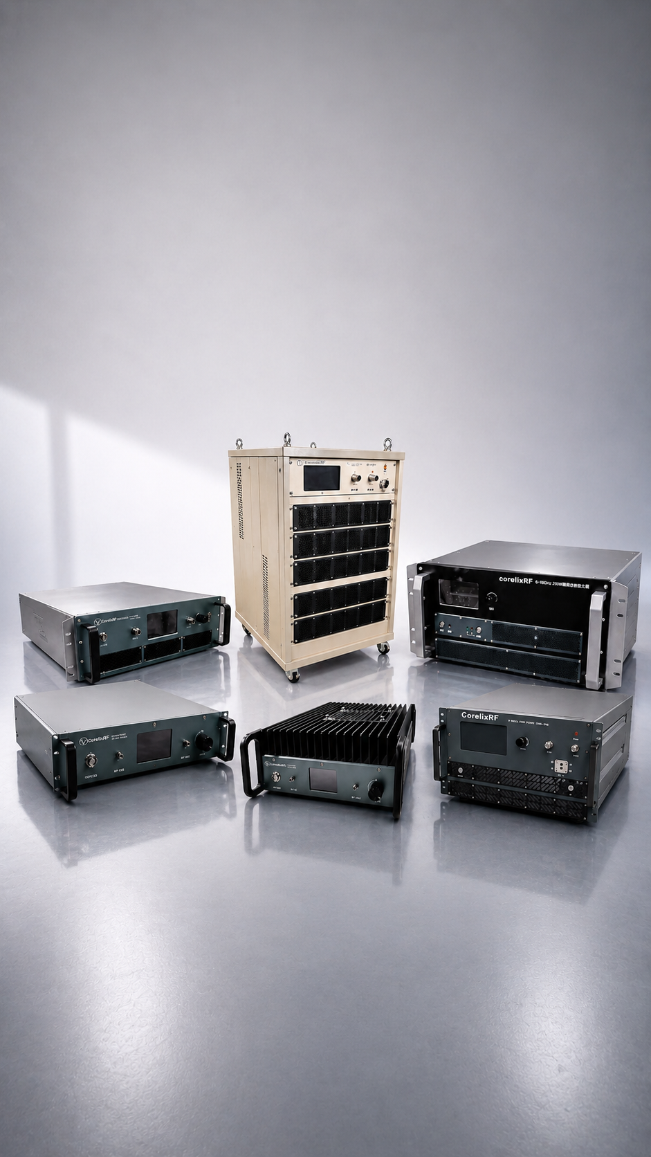
Standard RF Power Amplifier Modules
30 / 50 / 100 / 150 / 200 W
Select from four frequency families for RF testing, communications and system integration.
RF Engineering & Manufacturing
CorelixRF manufactures standard and custom RF power amplifiers for RF testing, communications and system integration.
Choose a standard platform or send your frequency, power and operating requirements.
Product platforms · RF testing · engineering capability
30+ Years
RF Engineering Experience
4 Standard Bands
Separate families across 30 MHz–6 GHz
5 Power Classes
30 W · 50 W · 100 W · 150 W · 200 W
RF · Microwave · mmWave
Standard and Project-Based Paths
Pulsed · EMC
Application-Specific Engineering Review
SDR · Antennas
Supporting RF Chain Hardware
RF Product Platforms
Explore standard RF amplifier modules and application-specific amplifier platforms.
Standard RF Amplifier Modules
4 frequency families / 30–200 W
Advanced RF Amplifiers
Microwave / mmWave / Pulsed / EMC
STANDARD
RF PA Platform
30 / 50 / 100 / 150 / 200 W
Select from four frequency families for RF testing, communications and system integration.
 MICROWAVE
Advanced Path
MICROWAVE
Advanced Path
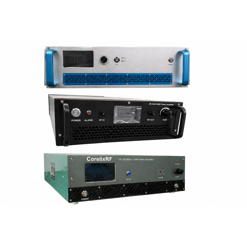
6–18 GHz / 18–40 GHz
Explore high-frequency options for test systems and RF subsystem integration.
 EMC / POWER
System-Level
EMC / POWER
System-Level
System-level / Project review
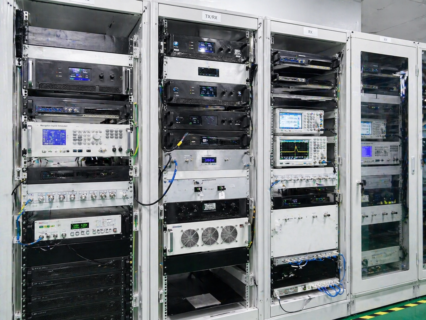
Review amplifier systems for EMC testing, radiated immunity and RF power injection.
 PULSED
Project Path
PULSED
Project Path
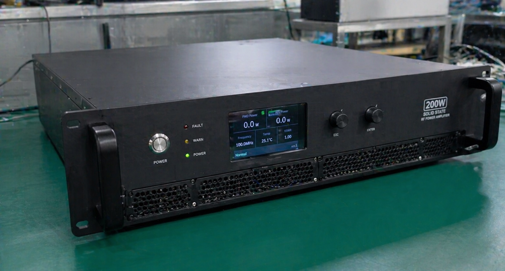
Pulse width / Duty cycle / Peak power
Discuss pulsed amplifier requirements for radar front-end evaluation and RF testing.
Advanced RF Amplifier Lines
Share frequency, waveform, cooling and interface requirements for application-specific amplifier selection.
Microwave / mmWave Platform Review
Pulsed / System-Level RF Support
01 // MICROWAVE
Confirm frequency, gain and output power for microwave testing or subsystem integration.
6–18GHz · View platform02 // MMWAVE
Review millimeter-wave coverage, packaging and thermal requirements for the intended system.
18–40GHz · Project review03 // SATCOM
Confirm band, output power, enclosure and integration requirements for SATCOM applications.
BUC · SATCOM04 // PULSE / EMC
Specify pulse width and duty cycle, or the required EMC test conditions.
Pulse · EMC · CustomEngineering Support
Discuss OEM/ODM amplifier requirements for frequency, output power, interfaces, cooling and mechanical integration.
Frequency & Power
Define the operating band, output power and waveform.
RF & Control Interfaces
Review connectors, control interfaces and monitoring requirements.
Mechanical & Cooling
Specify mounting, enclosure dimensions and cooling constraints.
Feasibility Review
Confirm technical scope, validation needs and project deliverables.
Frequency
Project-Defined
Operating band and bandwidth
Power
Project-Defined
Output power and operating mode
Review Inputs
RF + Thermal
Interfaces, cooling and installation
Product Path
Standard / Custom
Select a platform; review changes
Engineering Review Process
RF Chain Support
Complement your amplifier platform with SDR sources, antennas and custom integration support.
 SDR SUPPORT
RF Chain
SDR SUPPORT
RF Chain
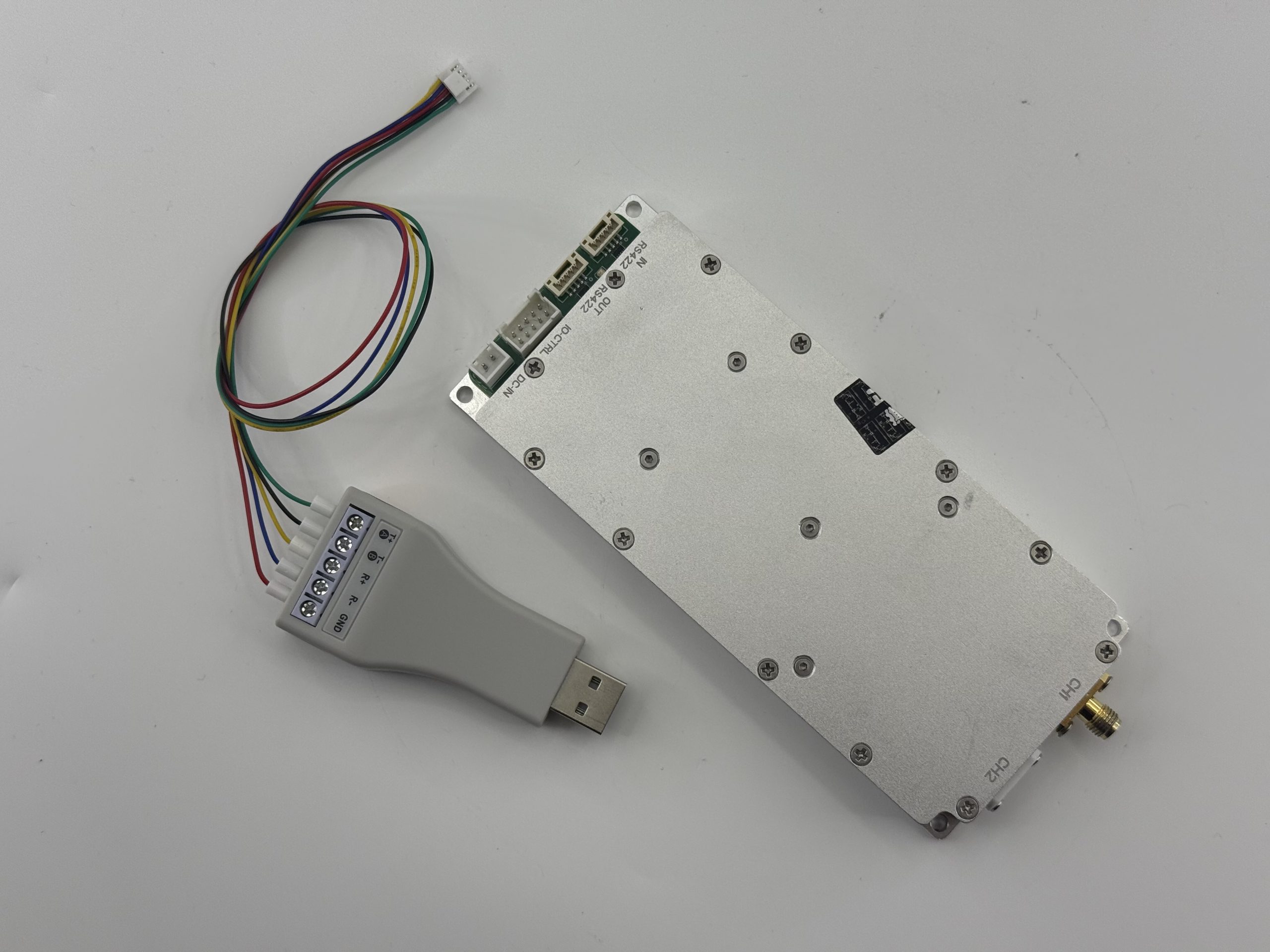
RF signal sources for waveform testing and amplifier-chain evaluation.
View SDR Support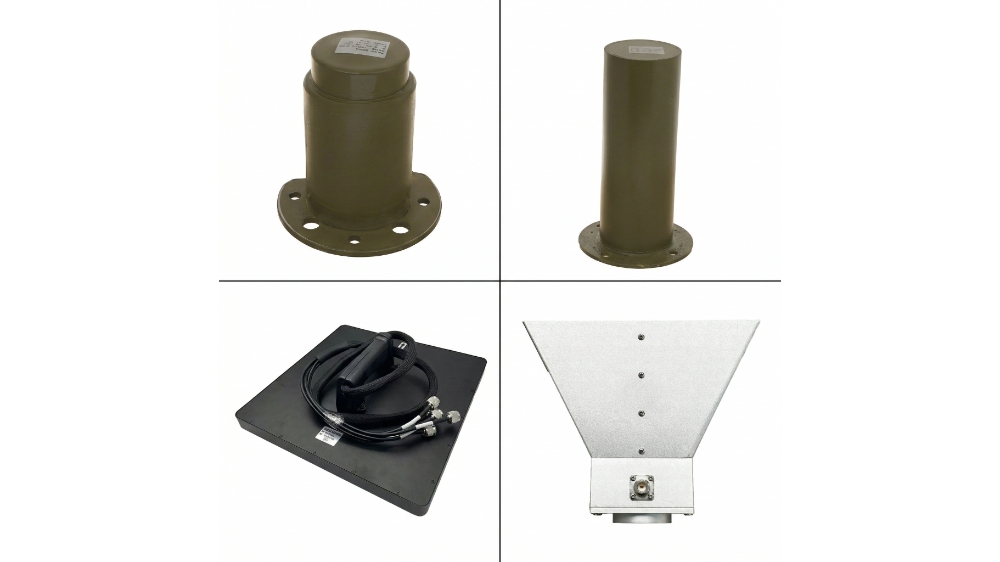 ANTENNA
RF Chain
ANTENNA
RF Chain
Antenna options for RF chain integration and system evaluation.
View Antenna Support CUSTOM
Project Review
CUSTOM
Project Review
Review changes to frequency, power, interfaces, cooling or mechanical design.
View Custom Amplifiers| Platform | Frequency Range | Power / Format | Typical Use |
|---|---|---|---|
| 30–512 MHz Modules | 30–512 MHz | 30–200 W | RF testing / Communications |
| 300–1700 MHz Modules | 300–1700 MHz | 30–200 W | RF testing / Integration |
| 300–2700 MHz Modules | 300–2700 MHz | 30–200 W | SDR chains / Broadband testing |
| 2–6 GHz Modules | 2–6 GHz | 30–200 W | RF testing / System integration |
| Microwave Amplifiers | 6–18 GHz | Project-dependent | Microwave testing / SATCOM |
| mmWave Amplifiers | 18–40 GHz | Project-dependent | High-frequency system evaluation |
| EMC Amplifier Systems | Application-dependent | System-level | EMC testing / Radiated immunity |
| Pulsed RF Amplifiers | Project-defined | Duty-cycle dependent | Pulsed RF testing |
| Custom RF Amplifiers | Project-defined | Project-defined | OEM / ODM integration |
Model specifications and operating modes require confirmation. Discuss Your Requirements
Who We Are
As an RF power amplifier supplier, CorelixRF combines RF engineering, manufacturing and testing for standard modules and custom projects.
GaN RF amplifier options are available for suitable designs; specifications and test data are confirmed by model.
Frequency Capability
Standard + Custom
Frequency coverage confirmed by model.
Power Output
30–200 W
Standard modules; higher-power projects reviewed separately.
Standard Families
4 Bands
Choose by operating frequency.
Standard Configurations
20
Four bands × five power classes.

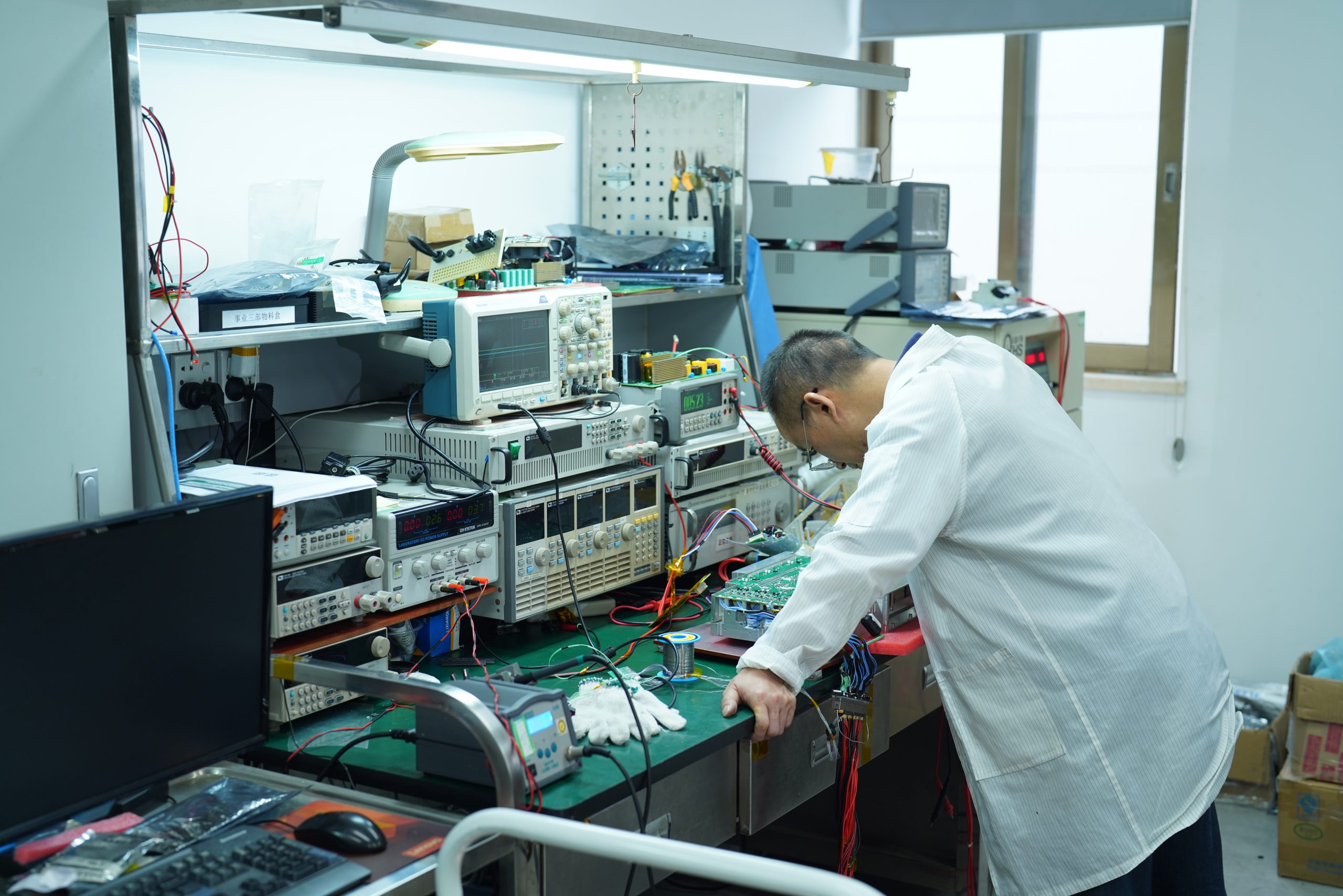
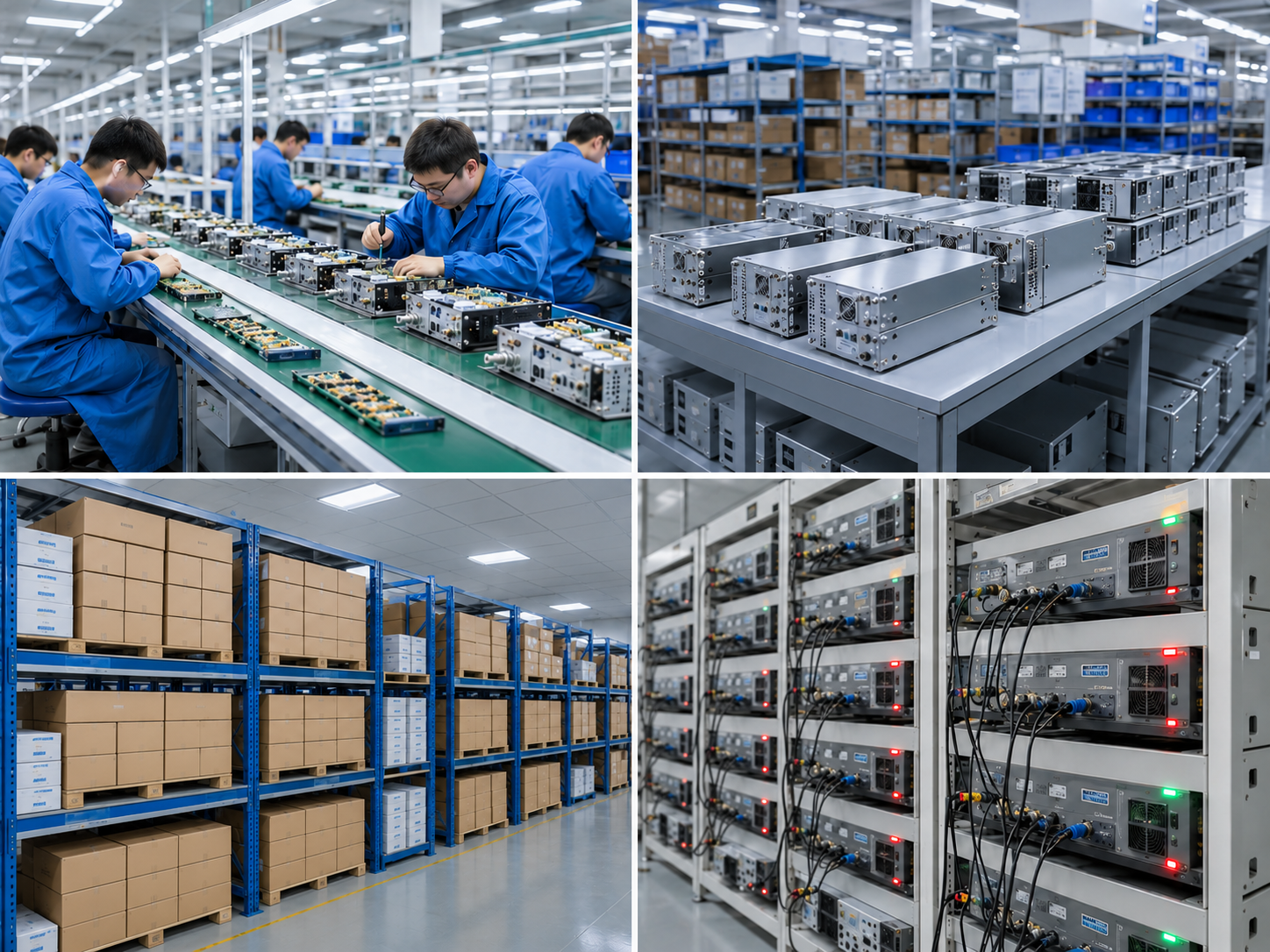
Production — CorelixRF Factory
In-House Engineering Chain
RF Design to System Integration
Why CorelixRF
Work directly with an RF amplifier manufacturer from requirement review through model selection.
01 // SUPPLY CHAIN
Discuss your requirements with the team responsible for amplifier selection and project evaluation.
MANUFACTURING · ENGINEERING REVIEW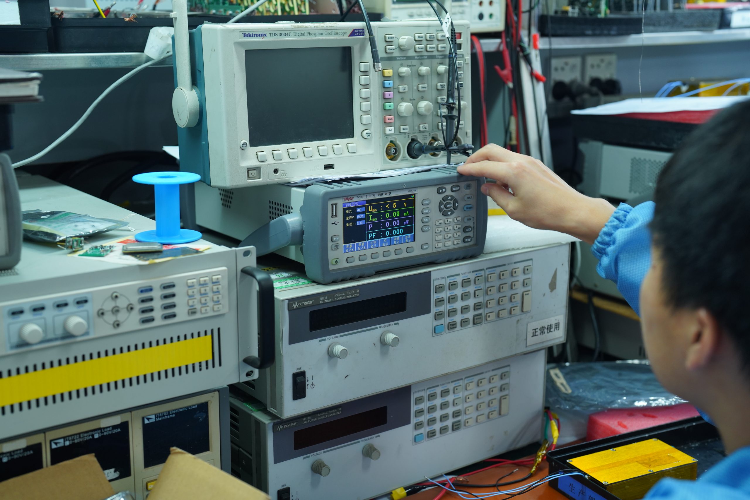
02 // PLATFORM CAPABILITY
Start with a standard module or review a design suited to your system.
GaN · High-Frequency Review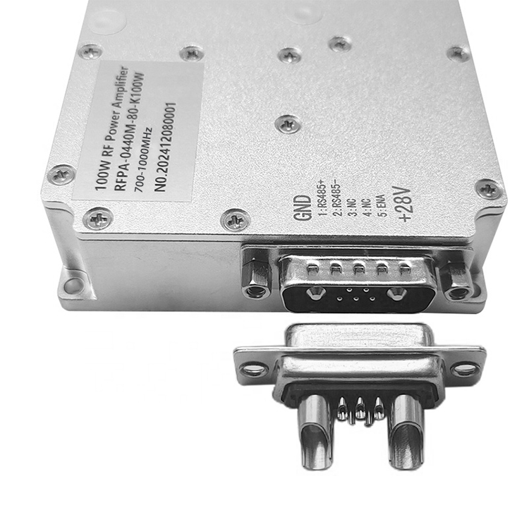
03 // VALIDATION
Confirm available measurements, operating conditions and documentation for the selected model.
RF TEST · DATA BY MODEL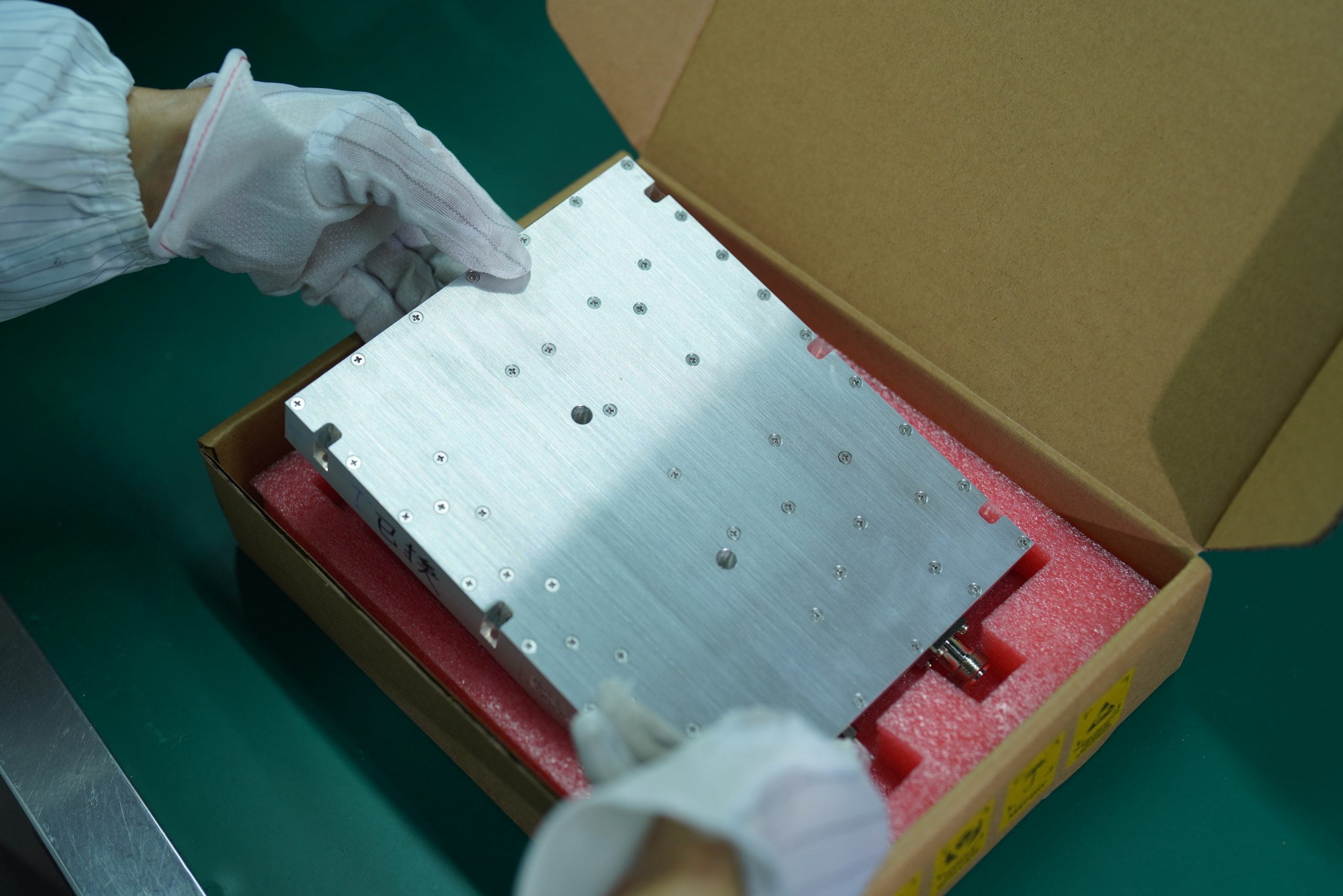
04 // PROJECT SUPPORT
Agree on interfaces, cooling, mechanical constraints and validation needs before quotation.
REQUIREMENT-BASED REVIEWEngineering & Manufacturing
Review how your amplifier is designed, built and tested.
RF Design & Thermal Engineering
RF matching, device selection and thermal design for amplifier modules and systems.
Module Assembly & CNC Machining
Housing, mechanical parts and module assembly coordinated with the RF design.
RF Performance Testing
Model-specific power, gain, spectrum and thermal checks, with test scope agreed.
Inspection & Documentation
Confirm inspection records, datasheets and project documentation before order approval.
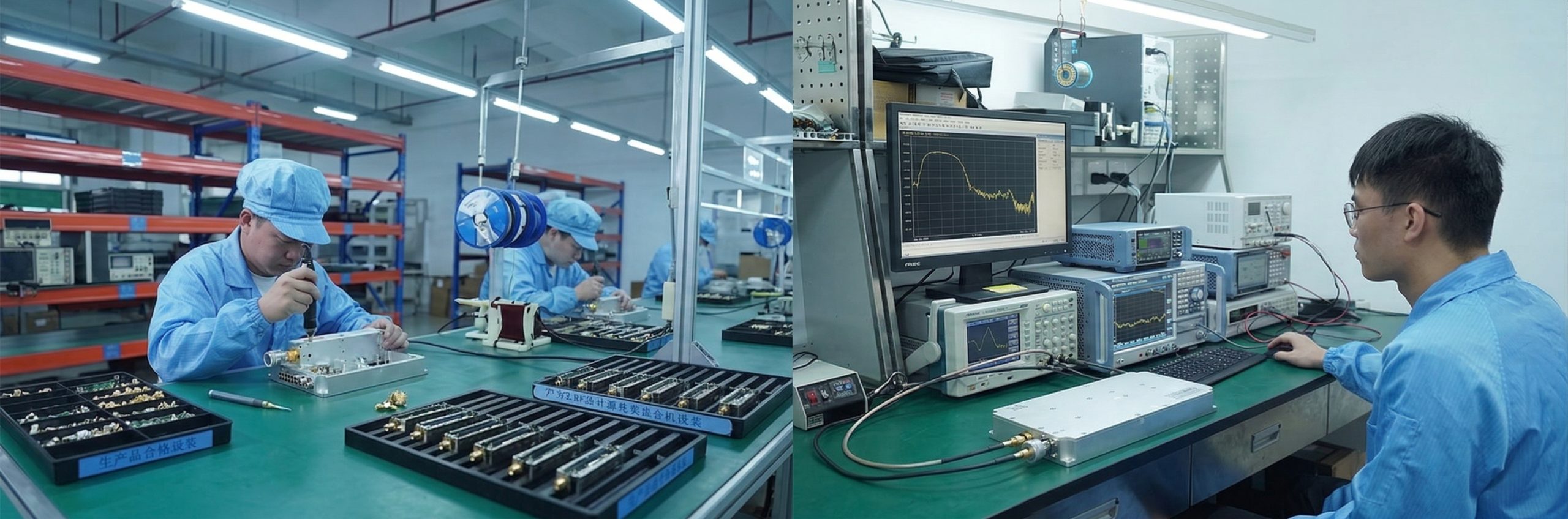
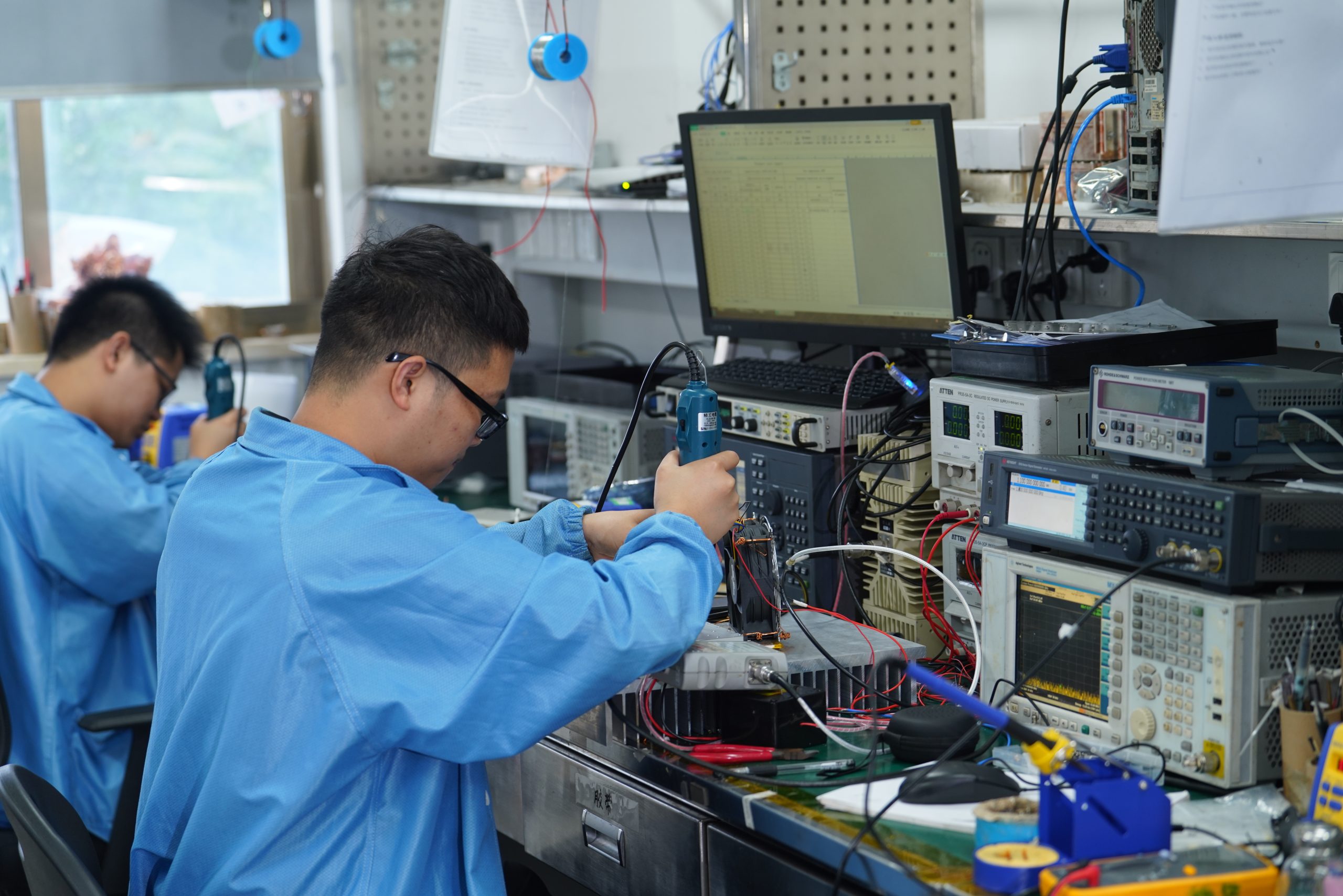
RF Testing — CorelixRF Laboratory

Assembly & Production
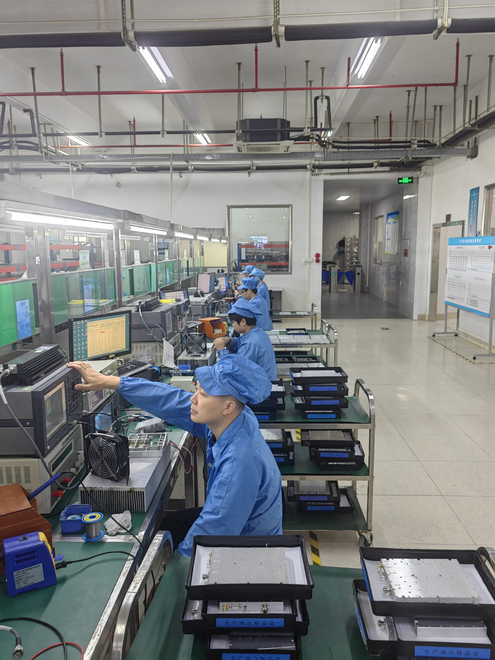
System Integration
4 Bands
Standard Frequency Families
5 Classes
30–200 W Standard Modules
Project-Based
Advanced Amplifier Projects
By Model
Specifications & Test Data
RF Amplifier Application Paths
Find the amplifier path that fits your application.
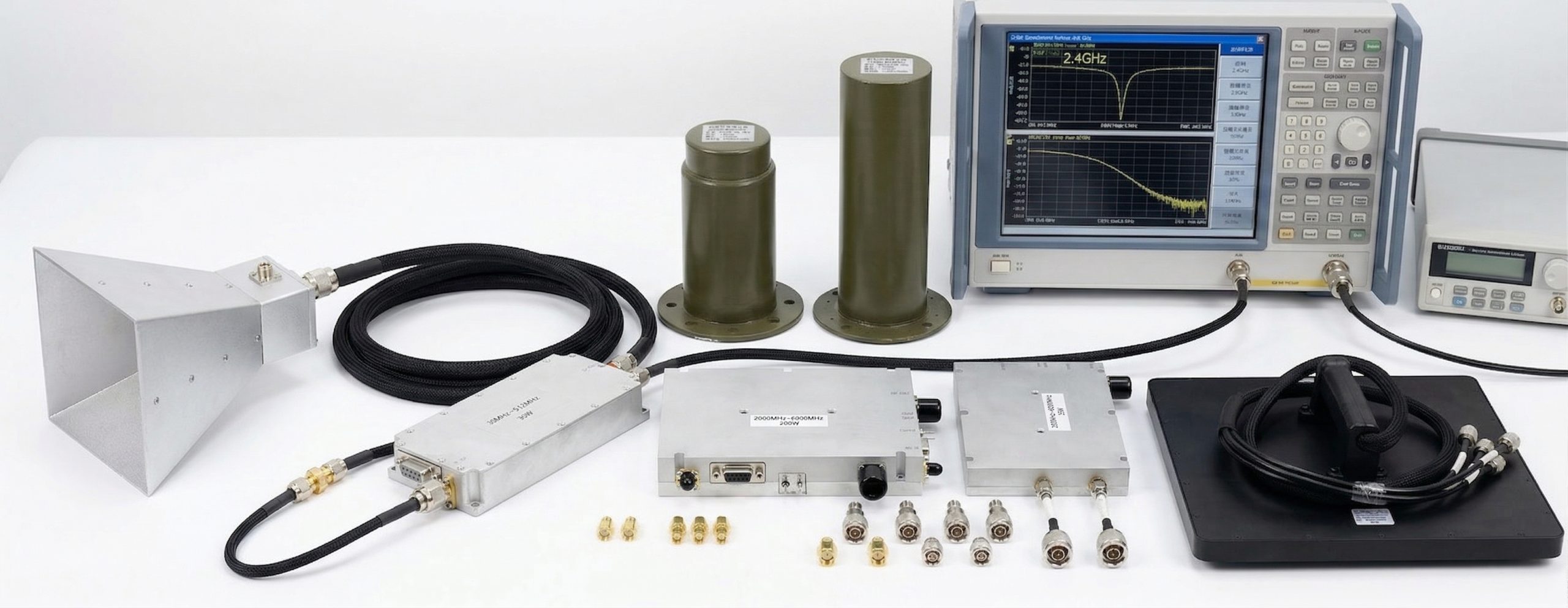 C-UAS
C-UAS01
RF amplifier integration for C-UAS systems, subject to project requirements.
EMC02
Amplifier platforms for radiated immunity and RF power injection tests.
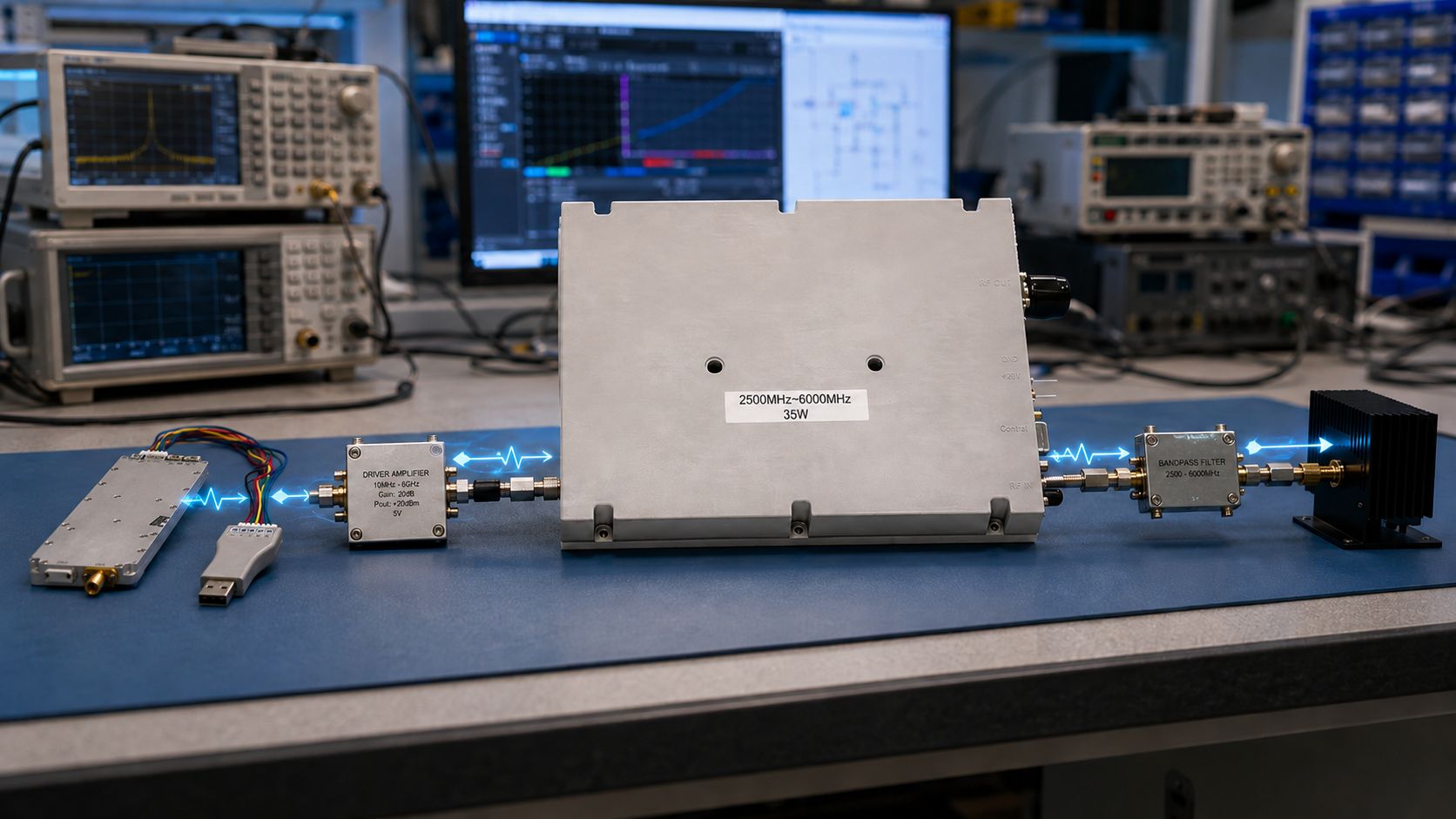 SDR CHAIN
03
Amplifier stages for SDR sources, drivers and downstream RF components.
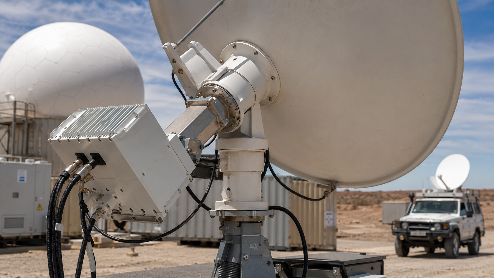 SATCOM
04
Review amplifier and BUC requirements for satellite communication systems.
RF TEST05
Amplifier options for signal generation, measurement and laboratory validation.
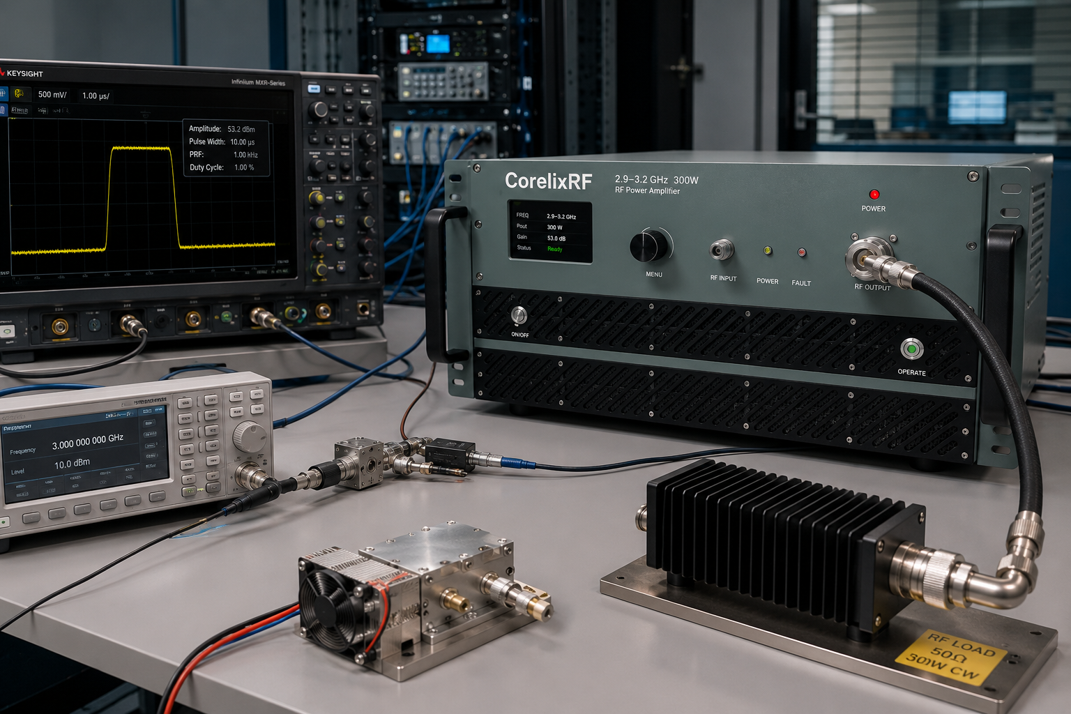 RADAR
RADAR06
Review pulsed operation and amplifier integration for radar front-end evaluation.
FAQ
Key questions before amplifier selection and quotation.
Compare frequency coverage, output power in the required operating mode, gain, cooling, protection, interfaces and model-specific test data.
The four families cover 30–512 MHz, 300–1700 MHz, 300–2700 MHz and 2–6 GHz. Each lists 30, 50, 100, 150 and 200 W configurations. Operating mode is confirmed by model.
Yes. Frequency, output power, cooling, enclosure and documentation requirements determine the suitable high-frequency project path.
Yes. Pulsed requirements should include peak power, pulse width and duty cycle. EMC projects should include test levels, loads or antennas, and cable loss where available.
Send frequency, output power, operating mode, input level, application and quantity. Include cooling, interfaces, mechanical limits and test requirements when known.
RF Requirement Review
Share your specifications to discuss a standard module or custom amplifier solution.
Useful details to provide
Add cooling, interfaces, mechanical limits and test requirements if available.
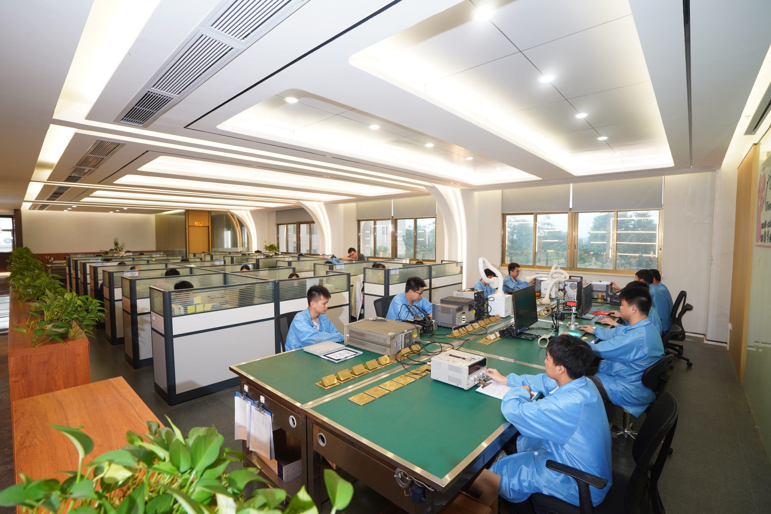
Engineering Support — CorelixRF
Resources
Explore datasheets, RF questions and technical articles.