EMC & Laboratory
RF Systems
Factory-direct RF amplifiers, SDR signal sources, antennas, and integration-ready RF hardware for EMC test benches, conducted/radiated RF setups, laboratory validation systems, and custom RF test chains.
→ Coupler → Antenna / Load → Analyzer
CorelixRF supplies RF hardware used inside EMC and RF laboratory systems. We manufacture and configure RF power amplifiers, SDR signal sources, antennas, load-side RF paths, rack-mounted platforms, and custom RF chains. We do not provide third-party EMC certification services; we support the RF hardware layer required for laboratory testing, validation, integration, and pre-shipment review.
Common RF Hardware Challenges in EMC and Laboratory Systems
The same amplifier can behave differently depending on cable loss, load condition, antenna VSWR, duty cycle, cooling, and measurement setup. CorelixRF helps review the RF hardware path before procurement or integration.
Laboratory validation often requires repeated or long-duration operation. If RF output drifts during testing, the result can affect repeatability, measurement confidence, and system-level validation.
When RF components are sourced from different vendors, frequency coverage, connector type, antenna power handling, control interface, and load conditions may not match the actual test setup.
Many laboratory projects require testing across multiple frequency bands. Using separate single-purpose components can increase setup complexity, procurement time, and integration risk.
Laboratory hardware often needs to fit inside racks, automated benches, or OEM validation systems. Mechanical structure, cooling, power supply, and control interface must be confirmed early.
Catalog values are not enough for engineering teams. Real output power, gain response, frequency behavior, interface information, and unit-level validation data are often required before deployment.
Buying the SDR, amplifier, antenna, cables, connectors, and enclosure separately can create unclear responsibility, longer technical confirmation cycles, and higher post-delivery debugging cost.
CorelixRF RF Hardware Paths for EMC & Laboratory Systems
CorelixRF manufactures and configures RF power amplifiers, SDR signal sources, antennas, and integration-ready RF platforms to help laboratory teams reduce hardware matching and deployment uncertainty.
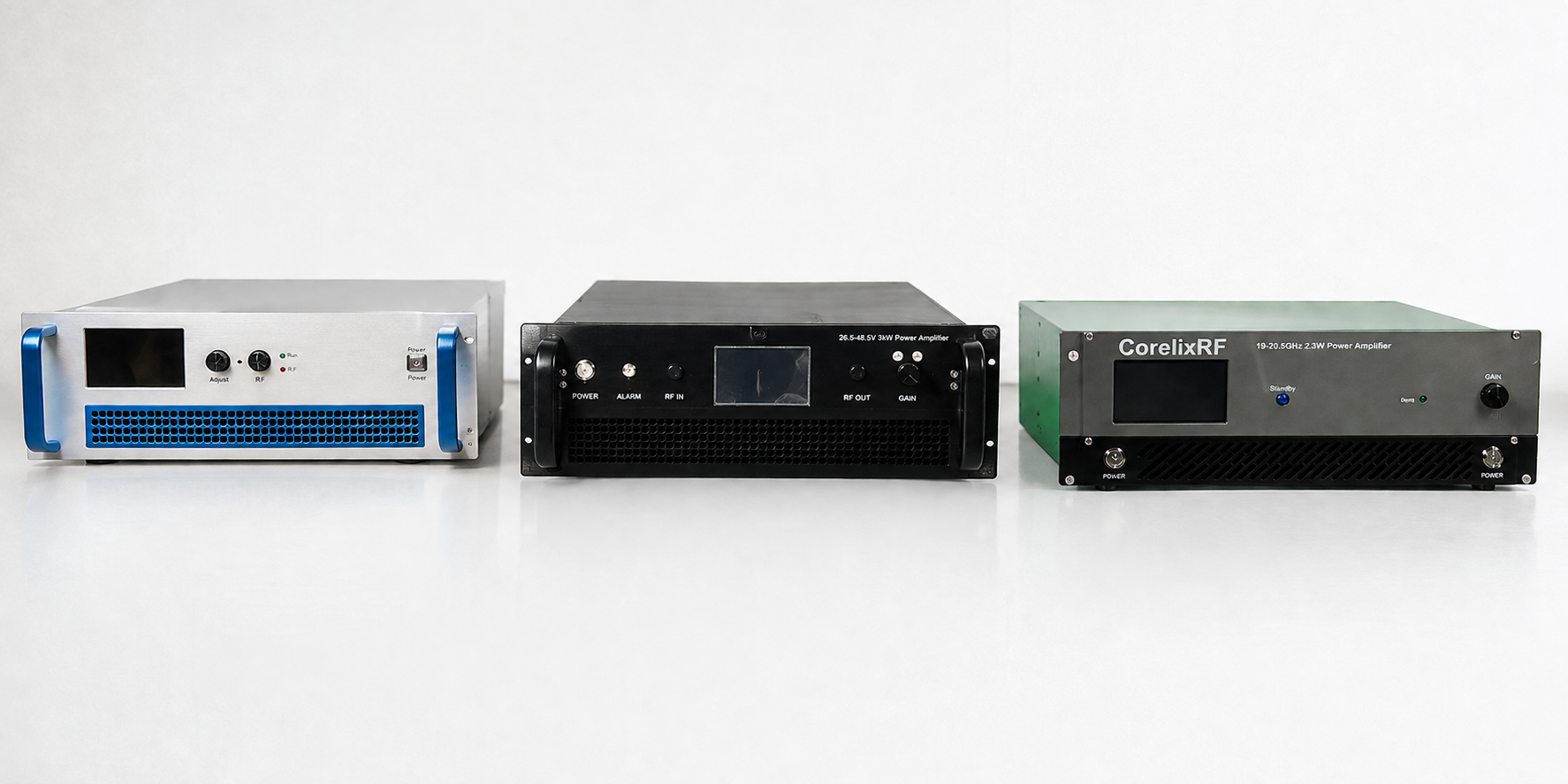
Factory-direct RF amplifier platforms for EMC test environments, RF stress testing, broadband signal amplification, product validation, and system-level RF simulation.
- Wideband and band-specific options
- CW and pulse configurations available
- Module-level or rack-mounted formats
- Protection and thermal design support
- Unit-level RF testing before delivery
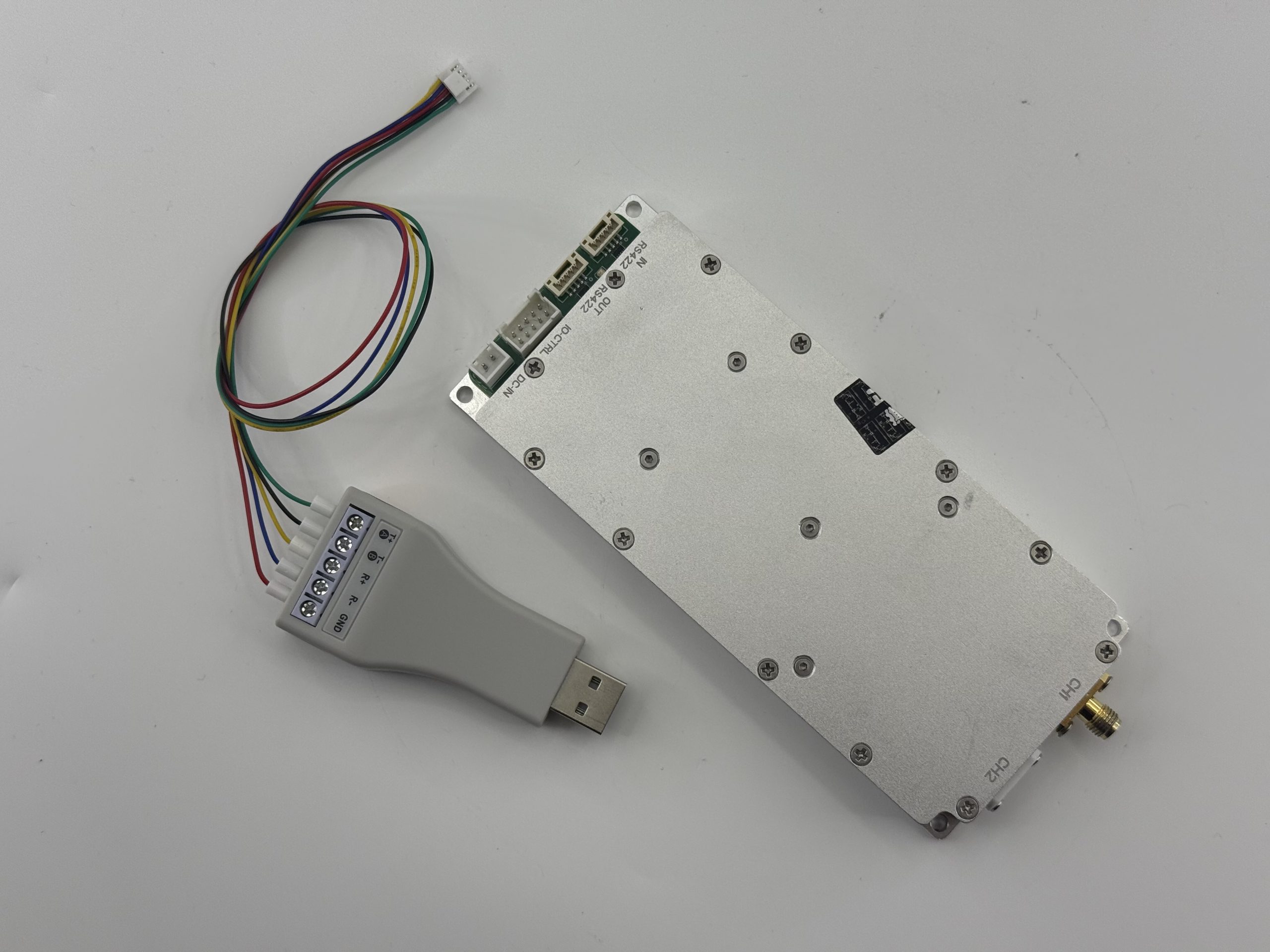
SDR-based signal source platforms for programmable RF generation, multi-band test input, repeatable signal environments, and laboratory RF chain development.
- Programmable RF source architecture
- Suitable for SDR + PA + antenna chains
- OEM board-level integration support
- Control interface confirmation
- Factory matching with amplifier and antenna options
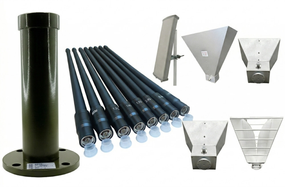
Broadband, directional, and receiving antenna options for laboratory transmission, monitoring, chamber support, bench testing, and directional RF validation.
- Omnidirectional and directional options
- Broadband and band-specific coverage
- Receiving and transmitting applications
- Connector and mounting options
- Matched with amplifier power requirements
Project-based support for matching signal sources, RF amplifiers, antennas, connectors, cables, control interfaces, and mechanical structures before hardware delivery.
- SDR + amplifier + antenna matching
- Rack-level integration support
- Connector and interface confirmation
- Cooling and enclosure review
- Custom project documentation support
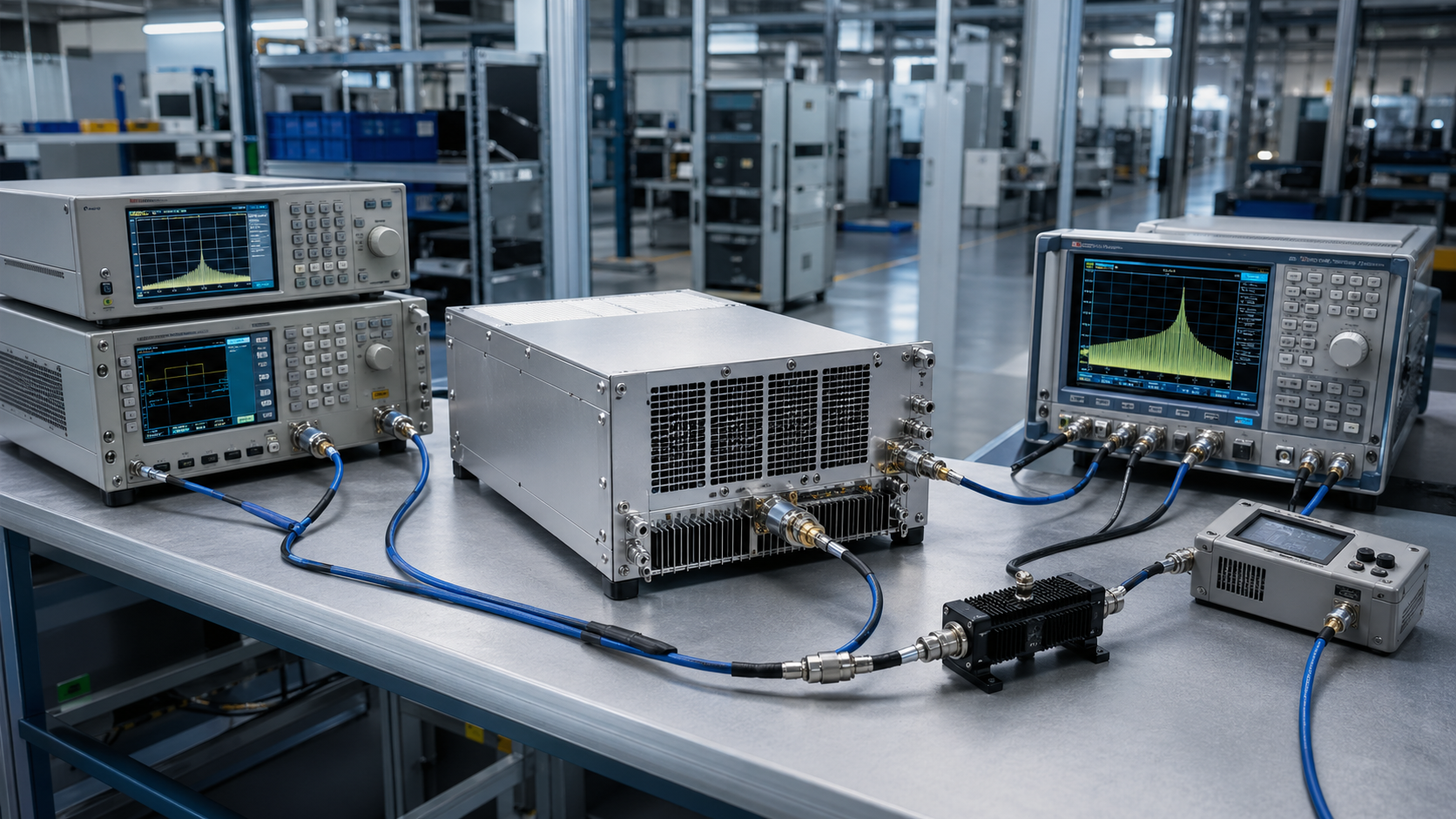
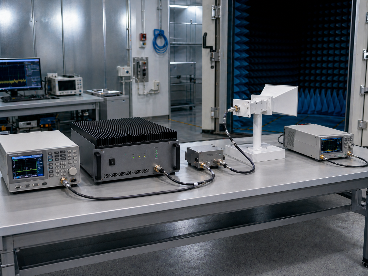
Typical RF Chain Architectures for EMC and Laboratory Systems
From basic RF benches to rack-mounted validation systems, CorelixRF helps customers configure RF hardware chains around frequency range, output power, antenna type, control interface, and integration format.
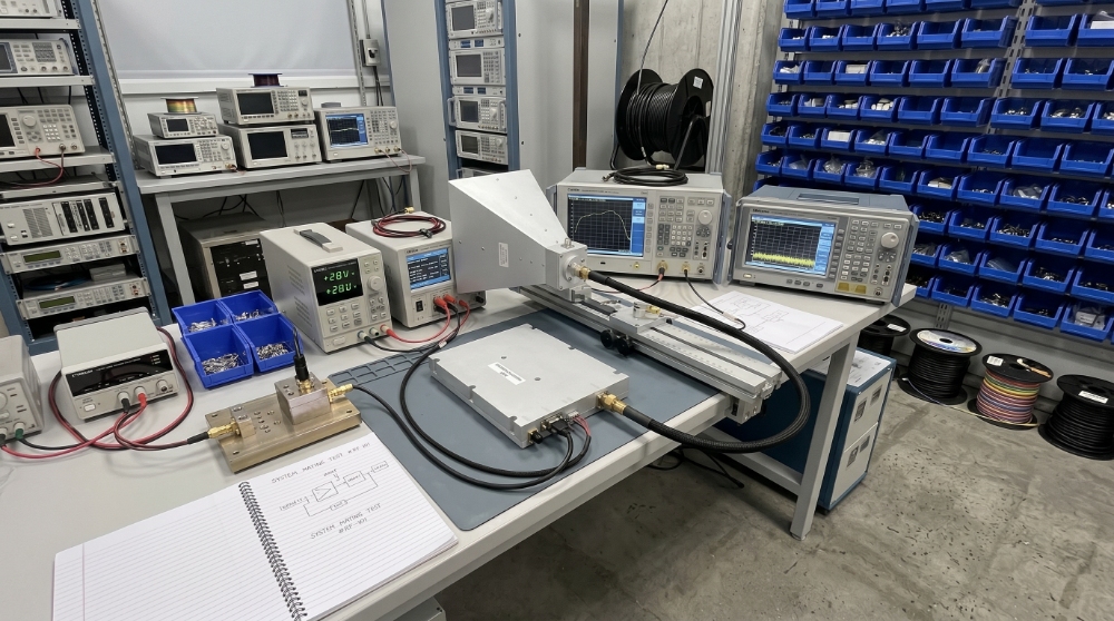
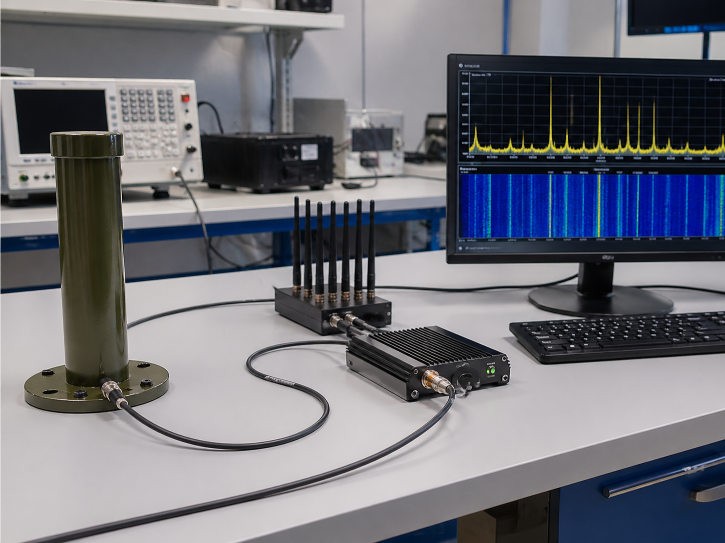
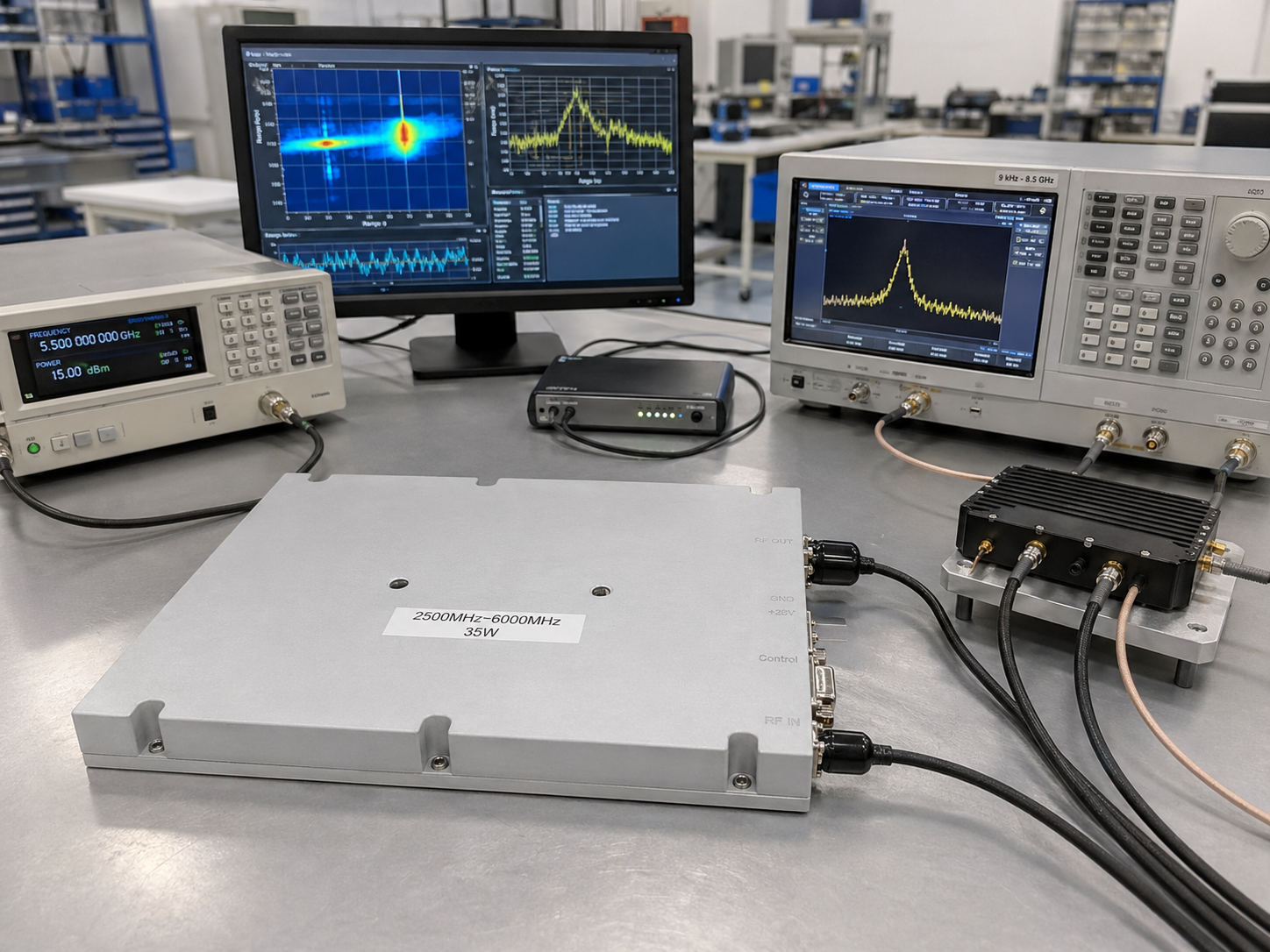
A basic RF laboratory setup for amplifier validation, RF output testing, spectrum observation, product development, and engineering bench testing.
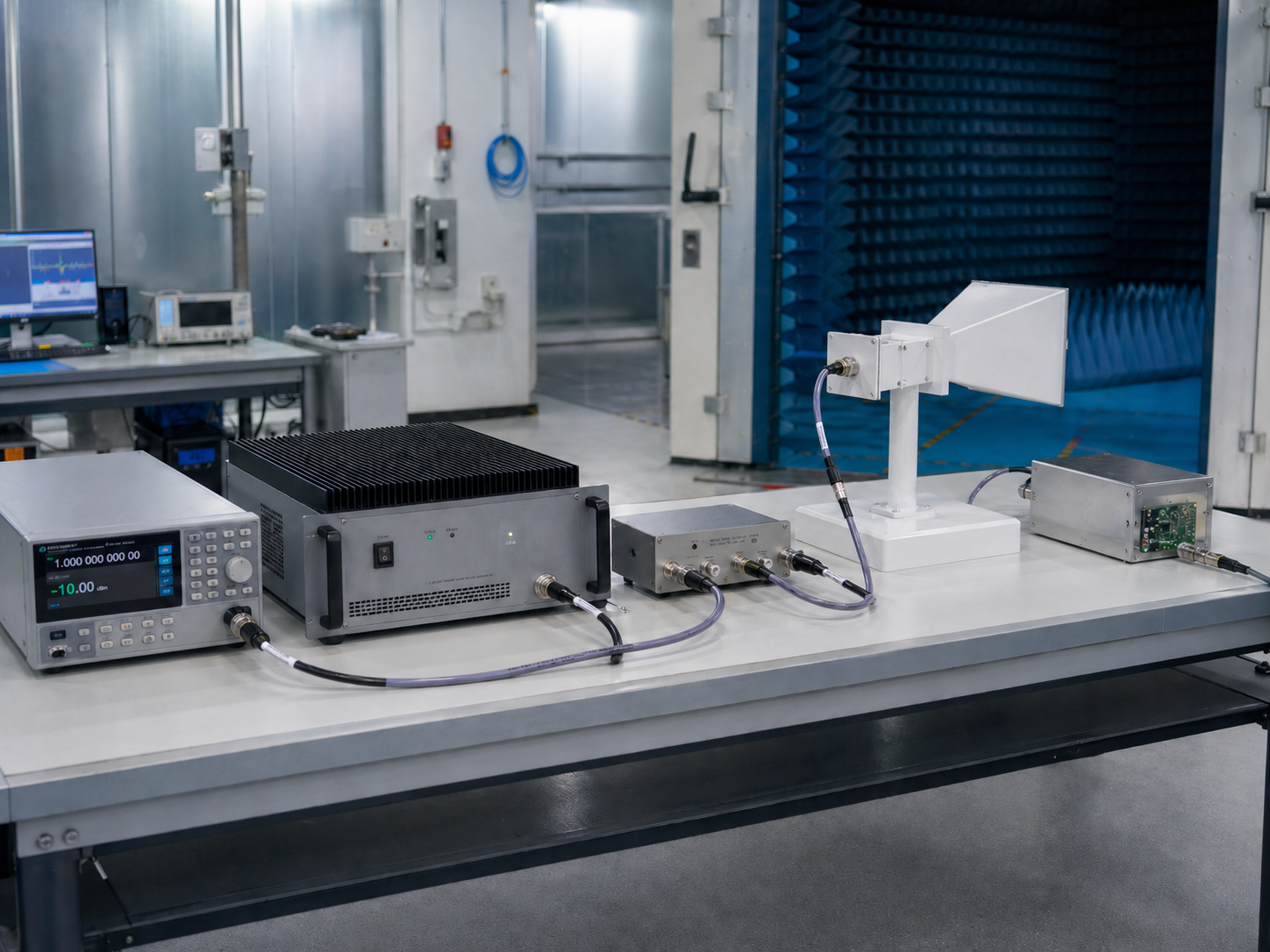
An RF hardware chain used to support EMC immunity environments, controlled RF exposure, device stress testing, and chamber-related validation setups.
CorelixRF provides RF hardware platforms used inside EMC and laboratory environments. We do not provide third-party EMC certification services. Our role is to manufacture and configure RF amplifiers, SDR sources, antennas, and integration-ready RF signal chains.
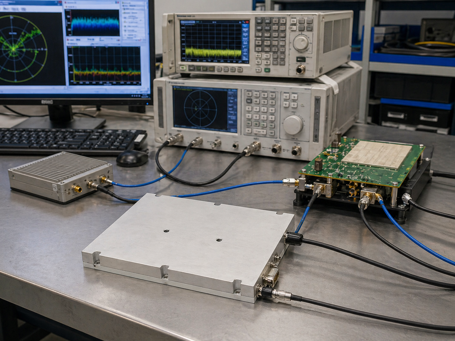
A receiving-side laboratory setup for spectrum observation, interference monitoring, signal environment analysis, RF occupancy review, and receiver-side validation.
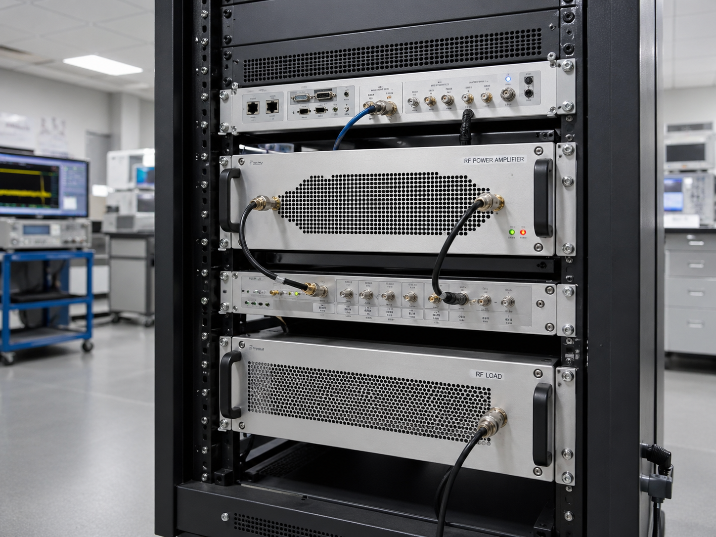
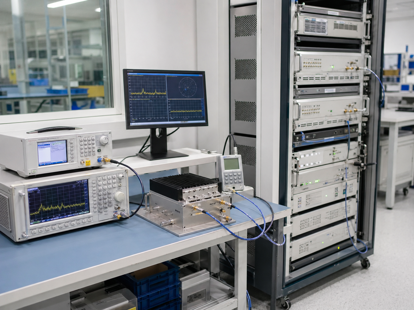
A rack-mounted RF hardware architecture for automated test benches, production validation, repeated RF test cycles, long-duration operation, and OEM laboratory systems.
RF Hardware Platforms for Laboratory Integration
CorelixRF hardware platforms can be supplied as standalone components or configured as matched RF chains for laboratory, validation, and system integration projects.

Factory-direct RF power amplifier platforms for EMC test environments, product validation, broadband signal amplification, long-duration testing, and system-level RF simulation. Wideband and band-specific options with CW and pulse support.
Programmable SDR-based RF signal source platforms for multi-band test input, repeatable signal environments, and SDR + amplifier + antenna transmit chain development. Board-level OEM format available.
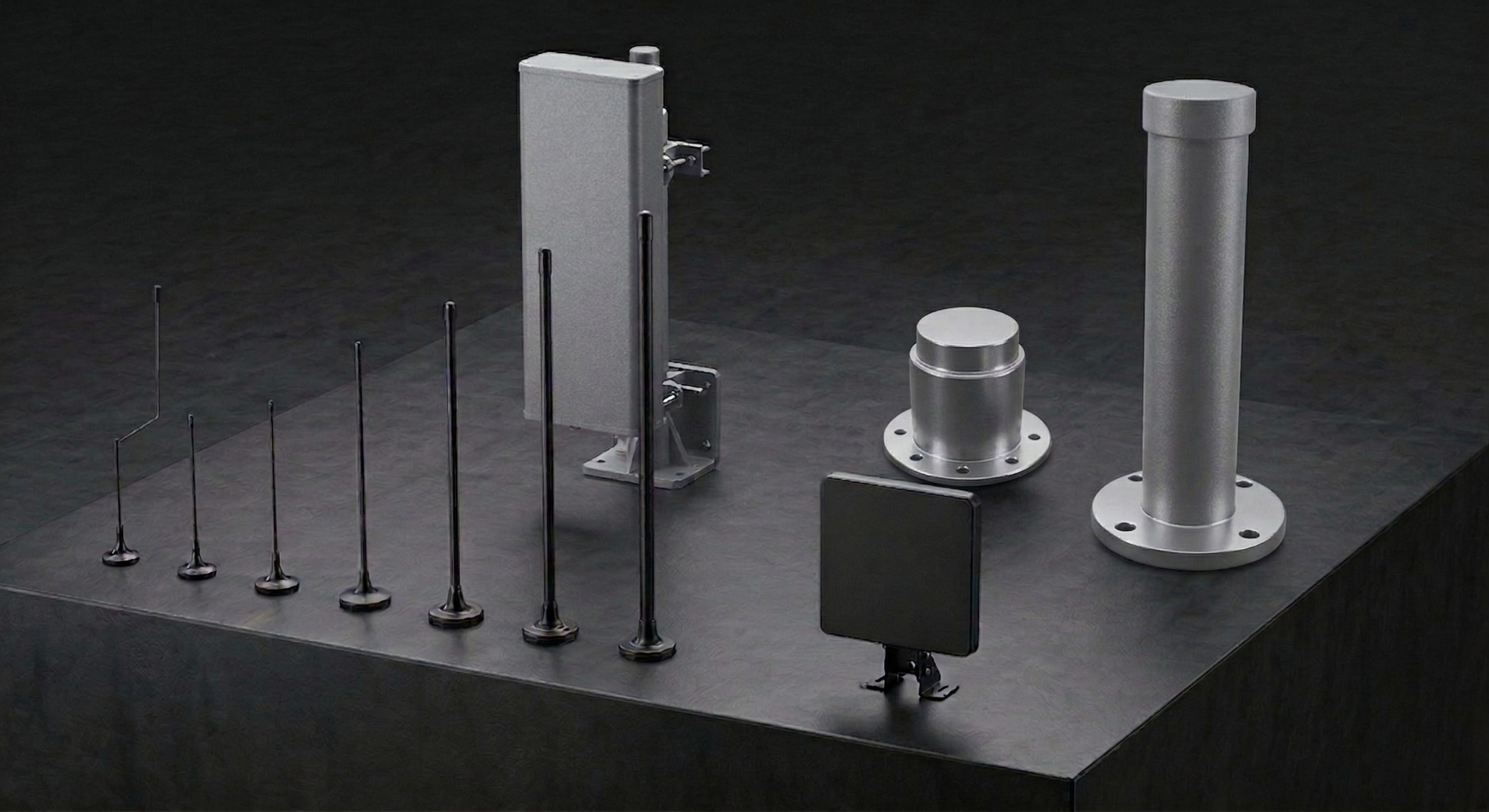
Broadband, directional, and receiving antenna options for RF transmission, monitoring, chamber support, directional testing, and laboratory signal chain output. Power handling confirmed to match amplifier output.
Project-configured RF hardware chains combining SDR source, RF power amplifier, and antenna into matched systems. Supports rack-mounted laboratory benches, OEM integration, and project-specific signal chain delivery.
Validated Product Paths for EMC & Laboratory RF Systems
Use these entry points to move from an EMC or laboratory application requirement into the most relevant CorelixRF hardware platform, then confirm final frequency, power, interface, cooling, and documentation needs with our engineering team.
For conducted/radiated setups, RF benches, immunity support paths, and broadband amplification.
For microwave lab benches, higher-frequency validation, custom RF chains, and specialized test racks.
For programmable RF generation, SDR + amplifier chains, custom waveform needs, and repeatable source-side control.
For antenna output, radiated RF setups, antenna range work, load-side review, and custom output paths.
Custom RF Hardware Support
for Laboratory Integration
For laboratory projects that cannot be solved by standard catalog models, CorelixRF supports project-specific adjustments in frequency range, output power, interface, enclosure, cooling, and system integration format.
Adjust RF hardware coverage around the customer's target band, validation range, or project-specific frequency plan.
Match the amplifier output level to DUT requirements, antenna power handling, test distance, load condition, and validation objective.
Confirm RF input/output connectors, power interface, control interface, and system connection details before production.
Support mechanical formats suitable for laboratory racks, automated benches, system cabinets, and OEM equipment integration.
Review cooling requirements for long-duration operation, continuous RF output, high-power testing, or compact installation environments.
Provide engineering documents, interface details, and unit-level test data to support laboratory system integration and validation.
Testing, Validation and Documentation Before Shipment
For laboratory RF hardware, measured data is part of procurement confidence. CorelixRF can review and document key RF, thermal, interface, load, and integration conditions before shipment.
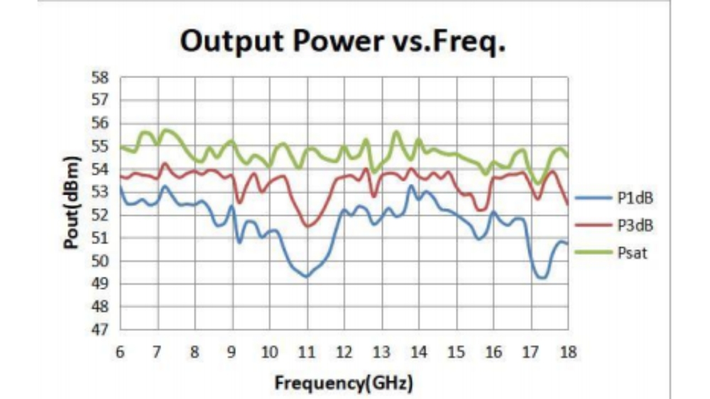
Confirm RF output capability across the required operating frequency range.
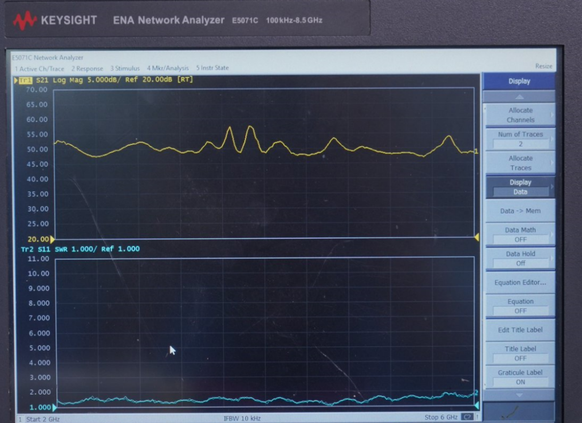
Review gain behavior, frequency response, and operating consistency across the specified band.
Evaluate RF output conditions and confirm suitability for the intended antenna, load, or system environment.
Review thermal behavior for continuous operation, long-duration testing, or high-power use cases.
Confirm control interface, connector layout, power interface, and system integration requirements before shipment.
Support engineering review with product-specific test information instead of relying only on catalog values.
- Output power across required band
- Gain and frequency response
- VSWR / return loss condition
- Dummy load and antenna path
- Thermal rise and airflow
- Long-duration operation review
- Connector and cable path
- Control interface confirmation
- Datasheet
- Unit-level test report
- Output power curve
- Gain curve
- Frequency response data
- Inspection record
- Packing photo
- NDA-based technical review
Measured data can support internal engineering review and procurement approval.
Output-side condition can be checked against antenna, load, DUT, or fixture needs.
Cooling, airflow, and long-duration use can be reviewed for lab environments.
Test, inspection, packing, and integration notes can be prepared when required.
Where EMC & Laboratory RF Systems Are Used
CorelixRF RF hardware platforms are used by engineering teams, laboratories, system integrators, and OEM developers that need stable, matched, and configurable RF signal chains.
RF hardware chains for EMC-related environments, including RF source, power amplification, antenna output, device exposure, and validation hardware support.
Used for amplifier testing, antenna matching, device validation, RF output checking, and signal chain debugging during product development.
Supports RF front-end validation, transmitter chain testing, receiver-side evaluation, and system-level communication hardware verification.
Used for controlled RF benches, compact RF hardware validation, avionics-related interface testing, and integration-oriented laboratory setups.
Supports RF source, amplifier, antenna, receiving, and measurement chains for radar, sensing, and RF front-end development projects.
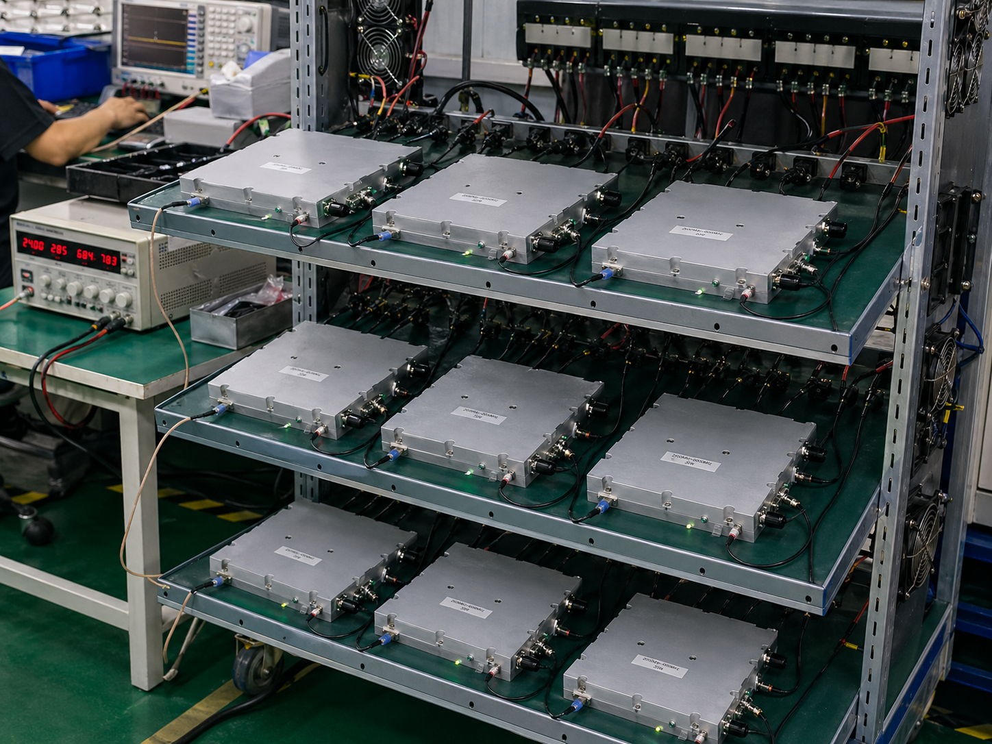
Used for repeated RF testing, long-duration operation, product validation, factory acceptance testing, and batch production verification.
Before You Choose RF Hardware for an EMC or Laboratory System
Choosing RF hardware only by catalog power or frequency range can create integration problems later. Review the full RF path, load condition, operating mode, cooling, and documentation requirements before procurement.
Output power alone does not mean the amplifier is suitable. The first step is confirming the required operating frequency range and usable bandwidth.
If the RF source, amplifier, antenna, load, and cables are purchased separately, connector mismatch, power mismatch, and system instability can appear during integration.
Laboratory validation often requires continuous operation. Cooling structure and thermal stability can be more important than short-duration peak performance.
Engineering teams should request actual test information such as output power, gain response, frequency behavior, interface details, and unit-level validation data.
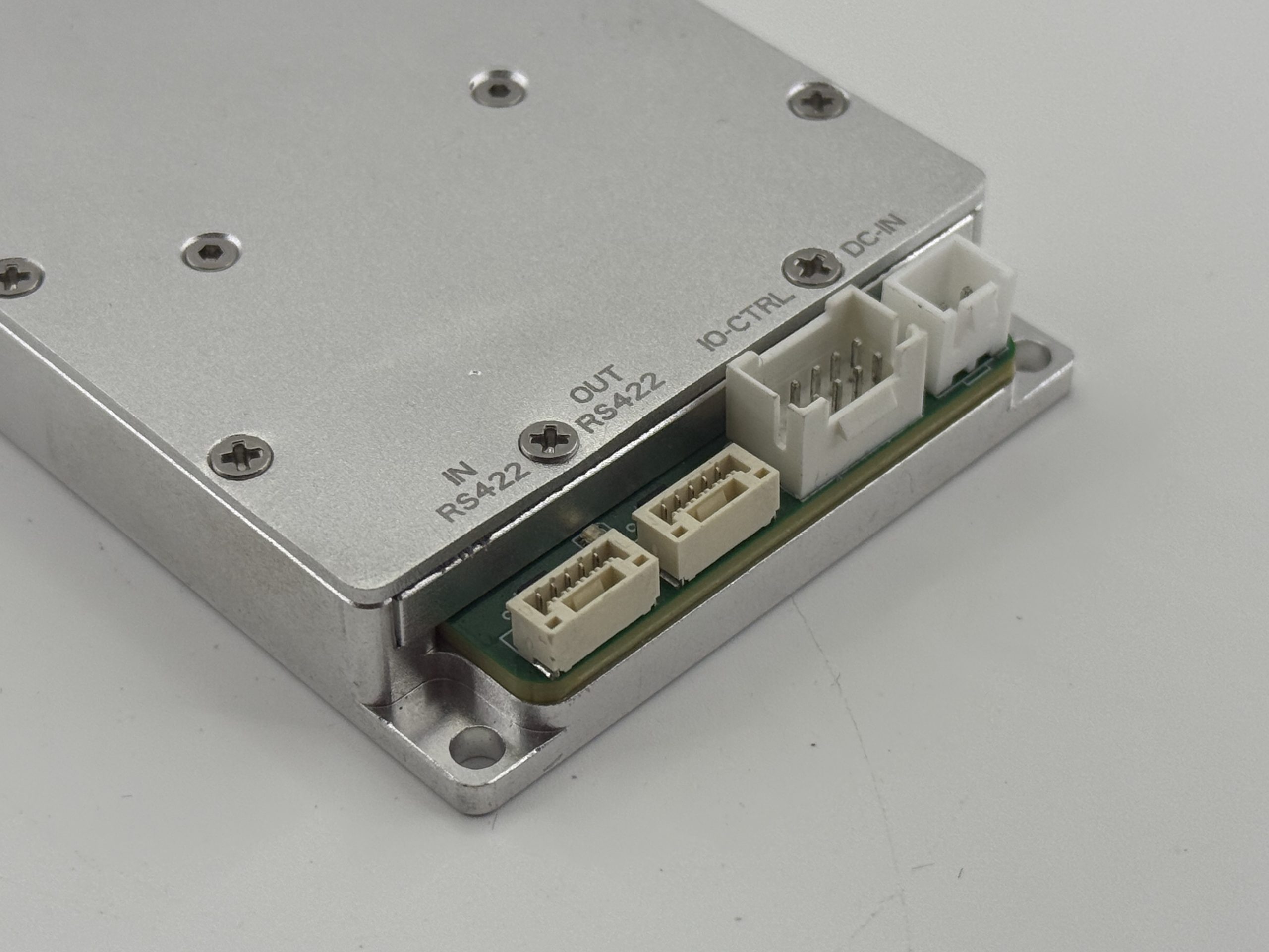
For rack-mounted or automated systems, control interfaces such as RS485, RS422, LAN, GPIO, USB, or project-specific protocols should be confirmed before production.
A supplier that only sells single components may not help solve signal chain problems. Laboratory systems require understanding of amplifiers, SDR sources, antennas, loads, interfaces, and mechanical integration.
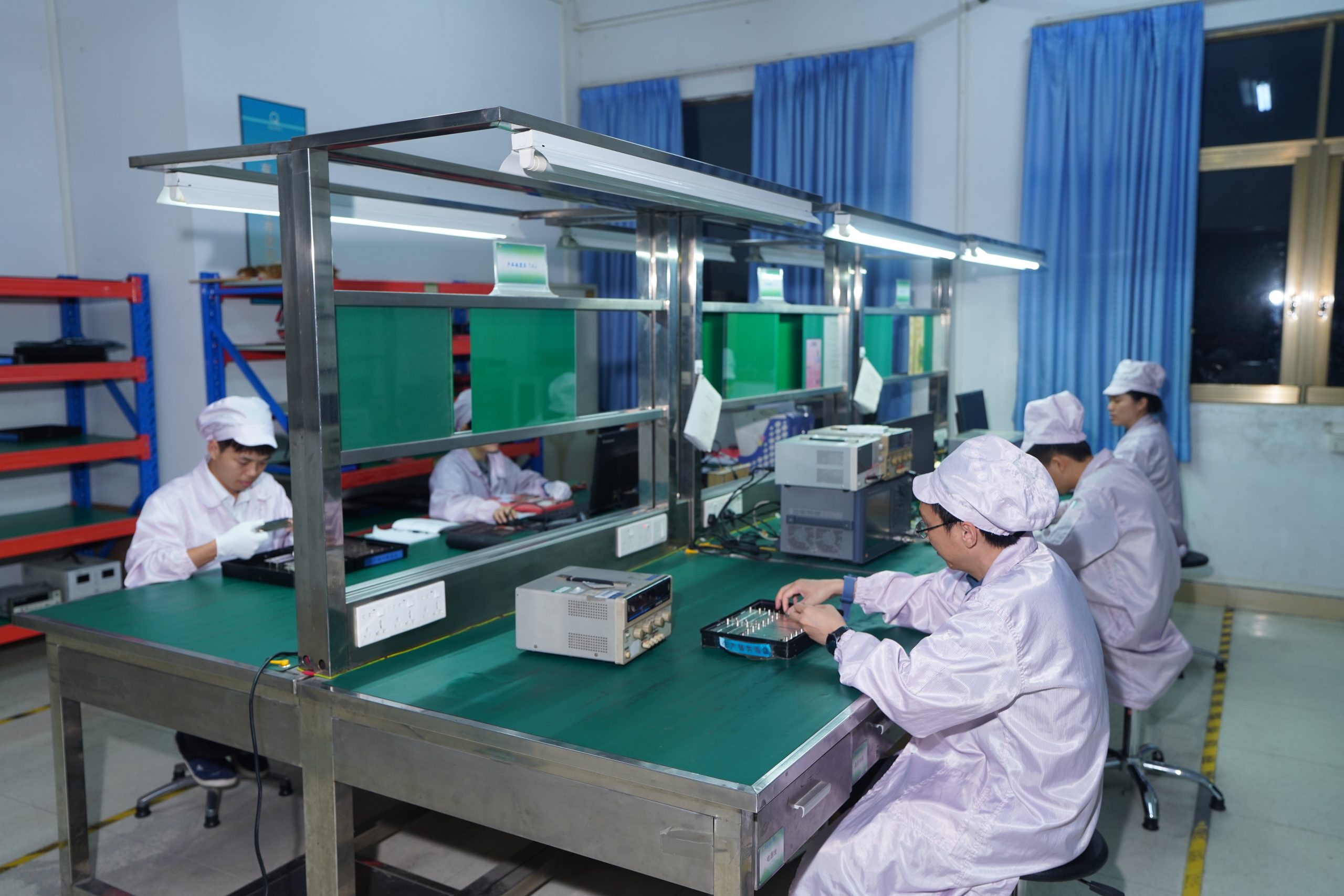
Factory-Direct RF Hardware with In-House Validation Support
CorelixRF is a factory-direct RF hardware manufacturer. We design, manufacture, and configure RF power amplifiers, SDR signal sources, antennas, and integrated RF platforms in-house — without intermediaries, trading companies, or third-party resellers.
Engineering teams working on laboratory systems, EMC environments, and product validation projects often face multi-vendor mismatch, unclear integration responsibility, and long procurement cycles. CorelixRF reduces this uncertainty by supplying matched RF hardware chains — from frequency range and output power to connector type, control interface, enclosure format, thermal structure, and unit-level validation — all configured before delivery.
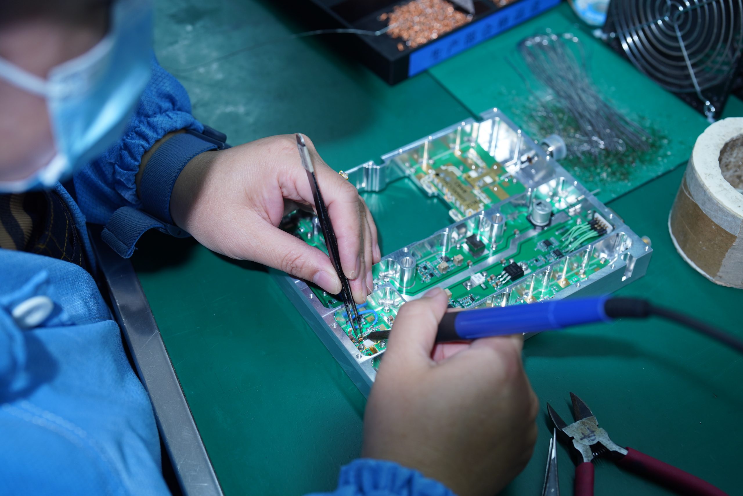
CorelixRF designs and builds RF amplifiers, SDR source platforms, and antenna hardware in-house. No reselling. No third-party assembly. Factory-direct from design to shipment.
SDR source, RF power amplifier, and antenna platforms can be matched and supplied together. This eliminates connector mismatch, power mismatch, and interface uncertainty across multi-vendor setups.
Project-specific adjustments are supported across frequency range, output power level, RF connector type, control interface (RS485 / RS422 / LAN / GPIO), enclosure format, and cooling structure.
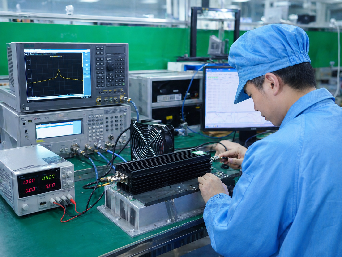
Every unit is checked against output power, gain response, frequency behavior, interface function, and thermal performance before shipping. Engineering teams receive real test data, not only catalog values.
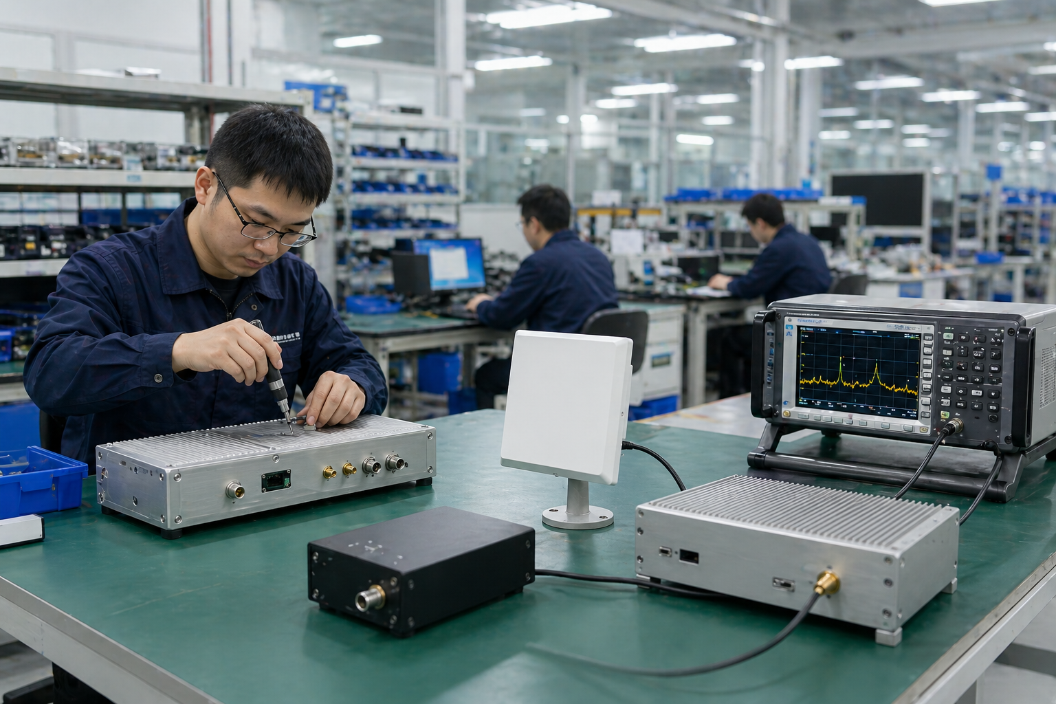
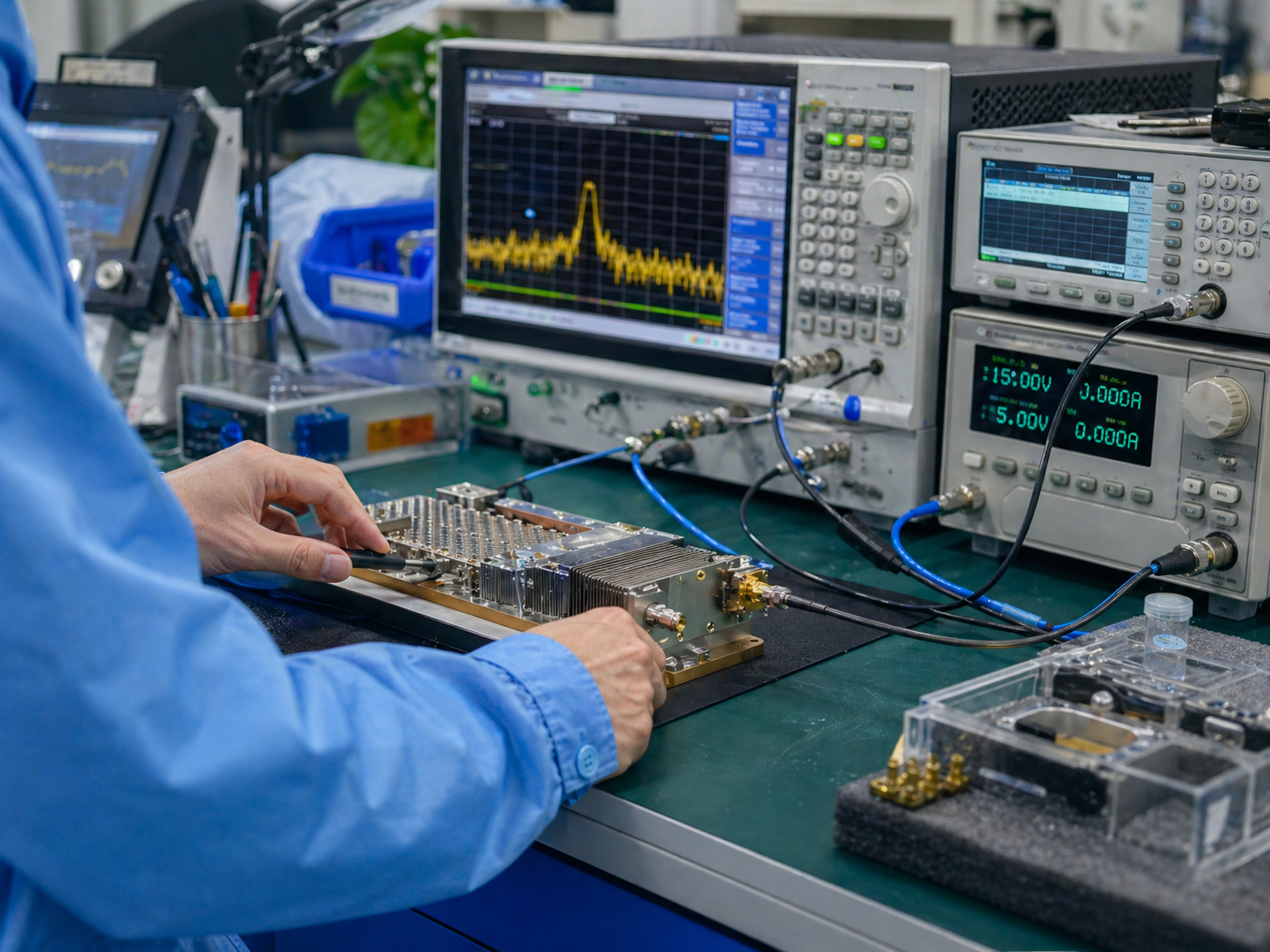
From Factory Test Bench to Laboratory Deployment
CorelixRF supports customers from RF hardware configuration and factory testing to packaging and delivery for overseas laboratory and integration projects.
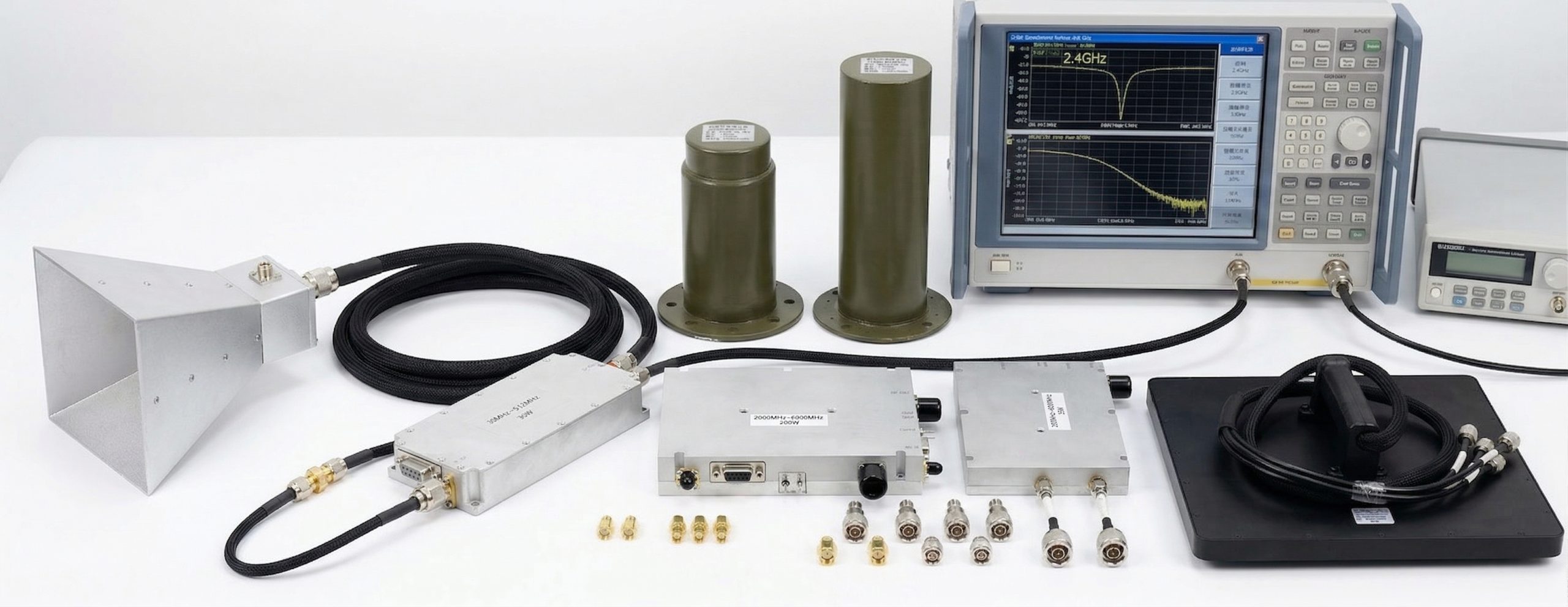
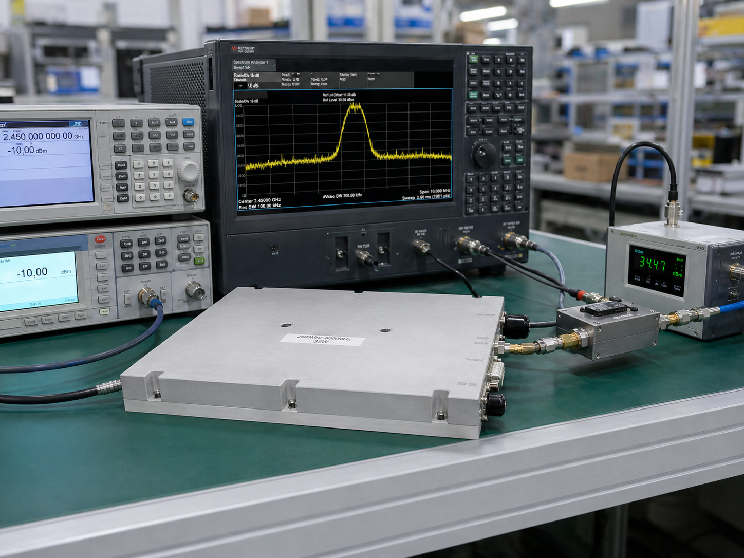
RF amplifiers and related hardware are tested using laboratory instruments such as signal sources, spectrum analyzers, network analyzers, power meters, couplers, and loads.
Mechanical structure, connector layout, interface access, cooling design, and rack or enclosure format can be reviewed for project-based integration.

Export-ready packaging helps protect RF hardware during international delivery and supports laboratory project deployment schedules.
FAQ: EMC & Laboratory RF Systems
Clear answers for buyers who need RF hardware for EMC-related benches, laboratory validation, rack integration, and custom RF test chains.
Submit Your Laboratory RF Requirement
Need RF Hardware for an EMC or Laboratory Test System?
Share your frequency range, output power target, signal source, load or antenna condition, DUT setup, operating mode, rack format, and documentation requirement. CorelixRF will help review the suitable RF amplifier, SDR source, antenna, or custom RF chain path.
To speed up engineering review, please share
- Target frequency range and bandwidth
- Required output power and operating mode
- SDR / signal source / external generator condition
- Antenna, dummy load, DUT, or fixture condition
- Connector, cable, coupler, or attenuator requirement
- Rack, bench, module, or enclosure format
- Required test data, curves, or documentation package
EMC & Laboratory RF Hardware Review — CorelixRF