Custom RF Systems for
Project-Specific Integration
Factory-engineered RF systems built around documented 9 kHz–50 GHz platform coverage, output power, control interface, mechanical structure, antenna match, SDR source and application environment.
Most custom RF systems start from existing CorelixRF amplifier, SDR, antenna or EMC platform paths, then are adjusted for frequency, power, interface, enclosure and validation requirements before shipment.
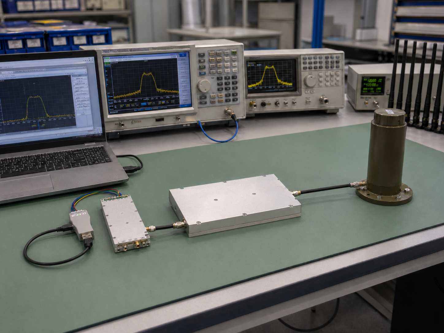 SDR → RF Amplifier → Antenna · Custom Chain Integration
Why Standard RF Modules Often Fail
in System-Level Projects
Standard frequency bands may not fully match the required project range, especially in broadband, high-frequency, EMC-oriented, or platform-specific applications.
Power level must be reviewed together with gain, duty cycle, signal type, thermal limits, load condition, and antenna power handling.
A module that works on the bench may not fit the customer's rack, chassis, payload bay, ground station, or rugged enclosure.
Projects may require RS485, RS422, LAN, GPIO, TTL, interlock, monitoring, or project-specific communication logic.
Without factory validation, system integrators face higher risk during installation, testing, and final deployment.
What We Customize
Customization at CorelixRF is not a vague promise — it means specific engineering decisions across frequency, power, platform, interface, structure, and validation.
Custom frequency coverage from kHz, MHz, GHz to mmWave and high-frequency microwave ranges, depending on project requirements and available RF platforms.
Watt-level, hundred-watt, kW-level, and high-power solid-state RF configurations can be reviewed based on frequency band, duty cycle, cooling, and system use.
CW, pulse, broadband, band-specific, rack-mounted, module-level, and system-level RF amplifier platforms can be configured.
SDR signal sources can be matched with RF amplifier stages for controllable signal generation, waveform output, and amplified RF chain development.
Amplifiers and antennas can be matched by frequency range, power handling, connector type, VSWR, and deployment environment.
RS485, RS422, LAN, GPIO, TTL, monitoring, interlock, and project-specific control options can be supported.
Module, rack-mounted, chassis-integrated, rugged enclosure, cable routing, mounting layout, and cooling structure can be customized.
Output power, gain, frequency response, VSWR, thermal behavior, control function, and system-level RF performance can be validated before shipment.
Custom RF System Configurations We Support
From power amplifier-centric builds to full RF chain integrations — CorelixRF supports eight system configuration types for project-specific requirements.
Custom RF Power Amplifier Systems
CorelixRF builds custom RF power amplifier systems based on required frequency range, output power, gain, duty cycle, cooling method, protection logic, control interface, and enclosure structure.
Explore RF Amplifier Platforms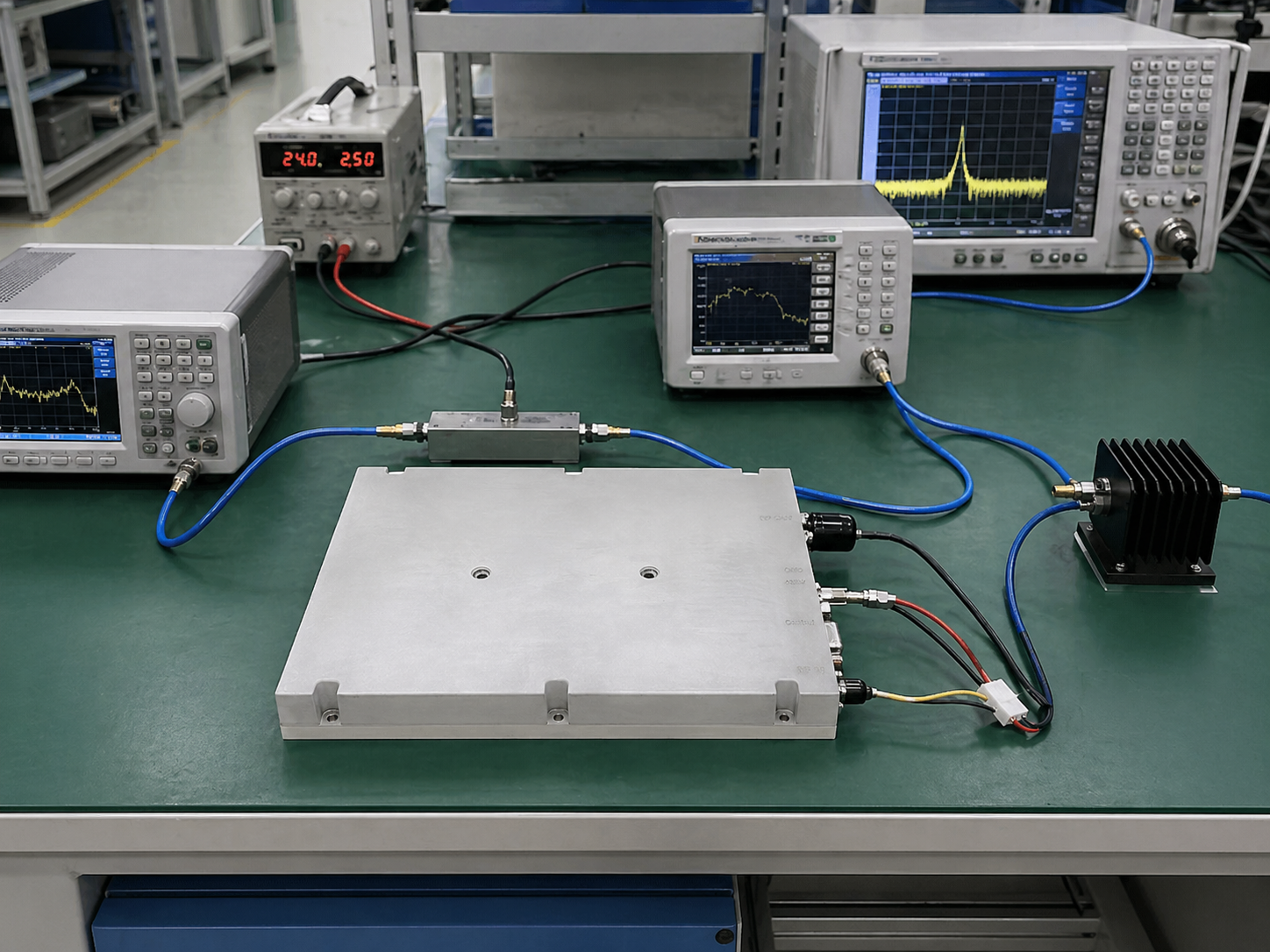
SDR + Amplifier Integrated Systems
For projects requiring signal generation and amplified RF output, CorelixRF can integrate SDR sources with RF amplifier platforms, control interfaces, and system-level output configurations.
explore This Configuration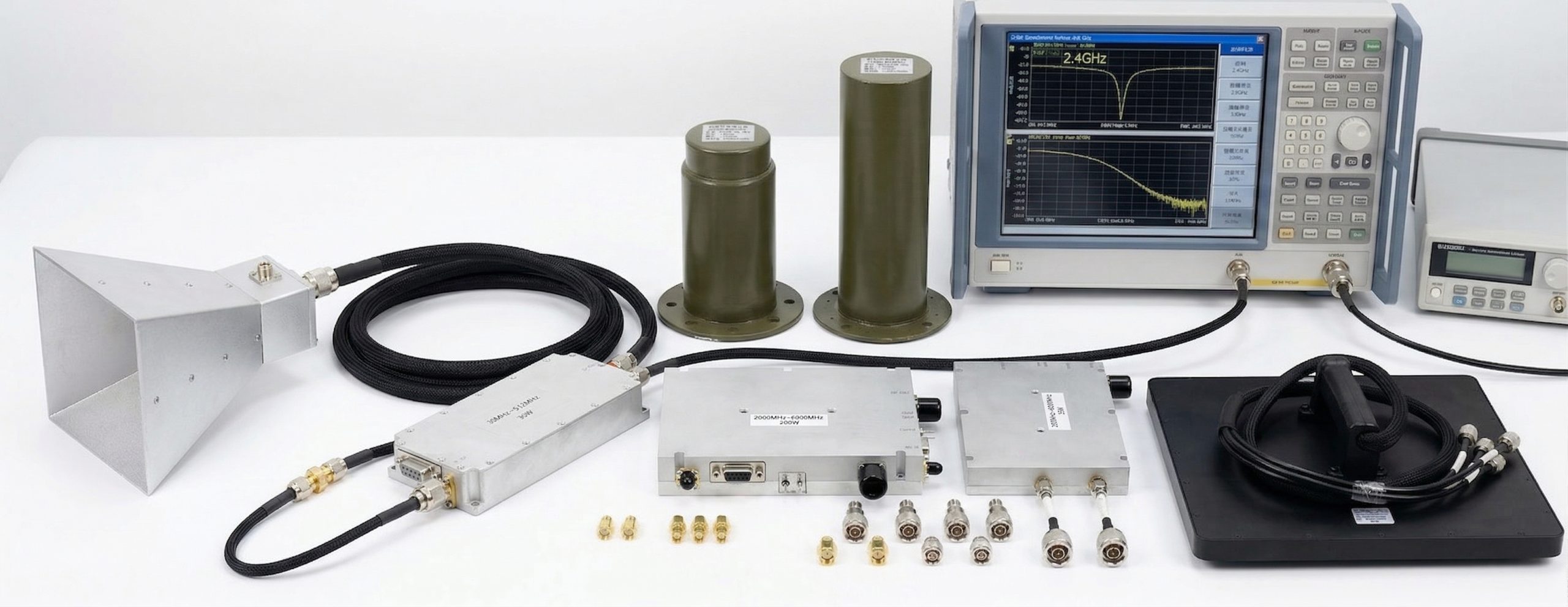
Amplifier + Antenna RF Platforms
Amplifier and antenna combinations can be matched based on frequency range, power handling, RF connector, VSWR, mounting method, and application environment.
explore This Configuration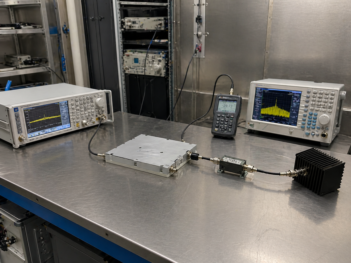
EMC RF Test Systems
CorelixRF supports EMC-oriented RF amplifier systems and test configurations for military, automotive, component-level, and civil EMC applications.
explore This ConfigurationProject-dependent review for SATCOM-related RF units, telemetry paths, channel equipment and monitoring modules where documented platform fit is available.
Project-Dependent Review19-inch rack configurations for lab, cabinet, ground-station, EMC, and system integration environments. 2U–5U structures with front/rear panel layout, cooling, and remote control support.
2U / 3U / 4U / 5U RackFor projects requiring mechanical protection or platform-level installation — chassis-integrated RF systems with controlled cable routing, mounting structure, cooling, and interface layout.
Field · Aerospace · IndustrialHigh-frequency and microwave assemblies reviewed by documented platform availability, micro-assembly capability and applicable project-level test scope.
High-Frequency · Project ReviewStandard Platforms Used as Custom Starting Points
Broadband and band-specific CW amplifier platforms for EMC, communication, test, measurement, and high-power RF systems.
View PlatformPulse amplifier platforms for radar pulse simulation, EMC, test environments, and complex electromagnetic environment applications.
View PlatformRF amplifier platforms for military EMC, automotive EMC, component-level EMC, and civil EMC test configurations.
View PlatformSDR source platforms for controllable RF signal generation, waveform output, and SDR + amplifier chain development.
View PlatformOmnidirectional, directional, broadband, and application-oriented antennas for amplifier matching and RF output systems.
View PlatformProject-dependent RF unit, telemetry path, monitoring module and power stage review against available platform paths.
Request Review19-inch rack systems for laboratories, EMC systems, ground stations, communication test platforms, and system integrators.
View PlatformHigh-frequency and microwave platform paths for project-specific RF assemblies, modules and channel equipment.
View PlatformHow We Build a Custom RF System
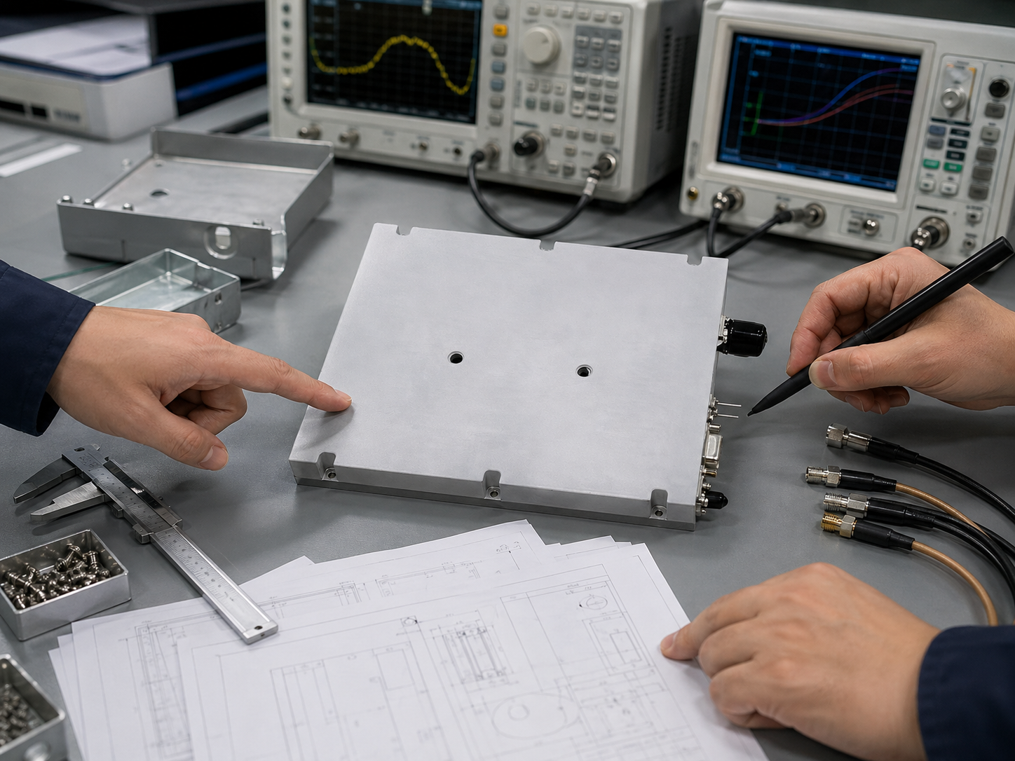
We review frequency range, output power, signal type, duty cycle, input level, gain requirement, interface, connector, size limit, cooling method, and application environment.
Our engineering team matches amplifier platform, SDR source, antenna, filter, coupler, load, power supply, cooling method, and control interface based on your system requirement.
CorelixRF provides a recommended RF chain, frequency and power configuration, mechanical structure, control interface plan, validation scope, and documentation plan.
Depending on project scope, we build a semi-custom configuration, engineering sample, rack-mounted system, chassis-integrated system, or interface-adapted RF platform.
Key RF, electrical, thermal, mechanical, control, and system-level parameters are verified before shipment according to the agreed test scope.
The system is delivered with test data, wiring guidance, interface instructions, mechanical information, packing support, and shipment documentation.
What We Verify Before a Custom RF System Ships
Validation scope can be reviewed based on application, frequency band, power level, duty cycle, enclosure structure, and documentation requirement.
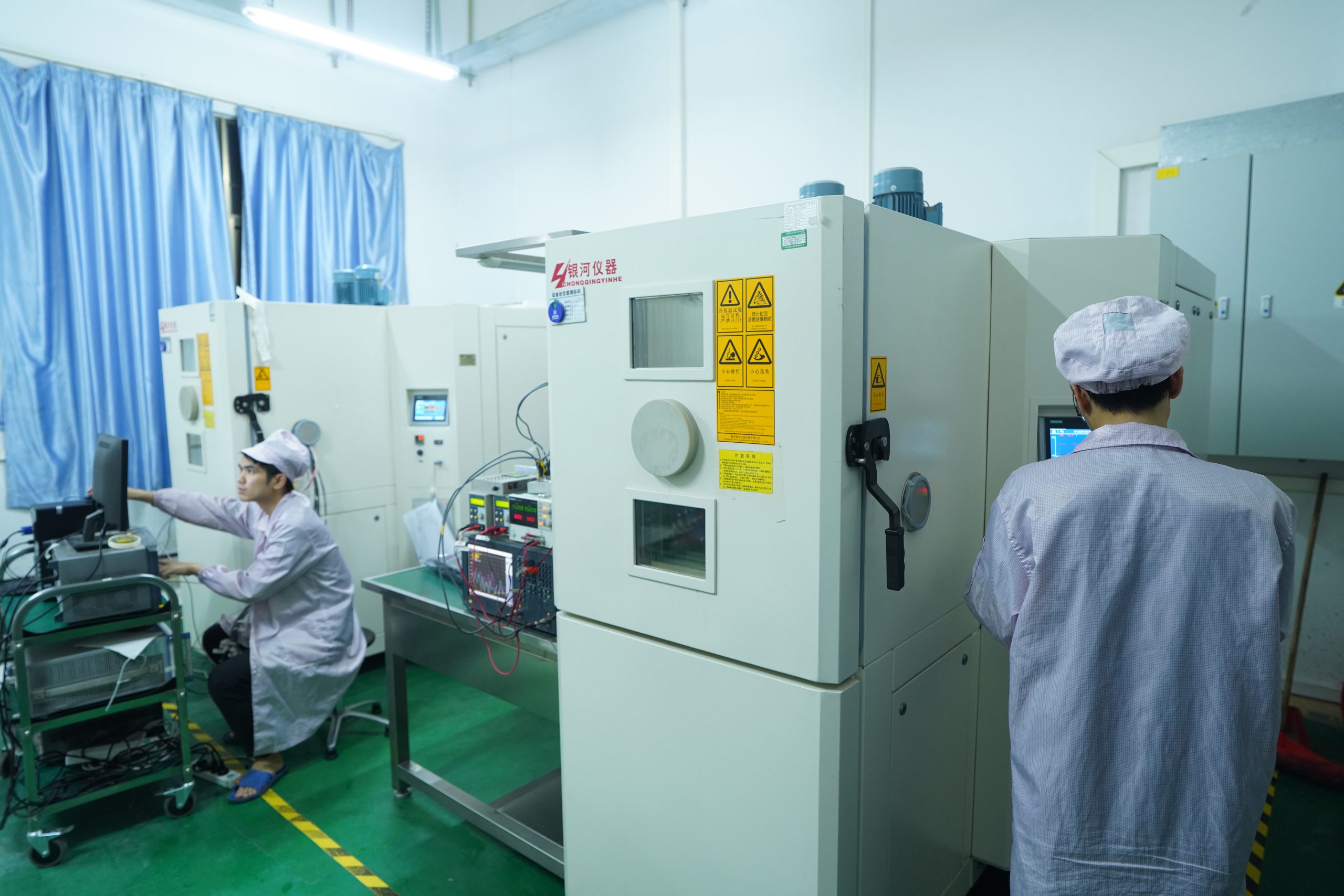
Factory-Direct RF Engineering and Manufacturing Capability
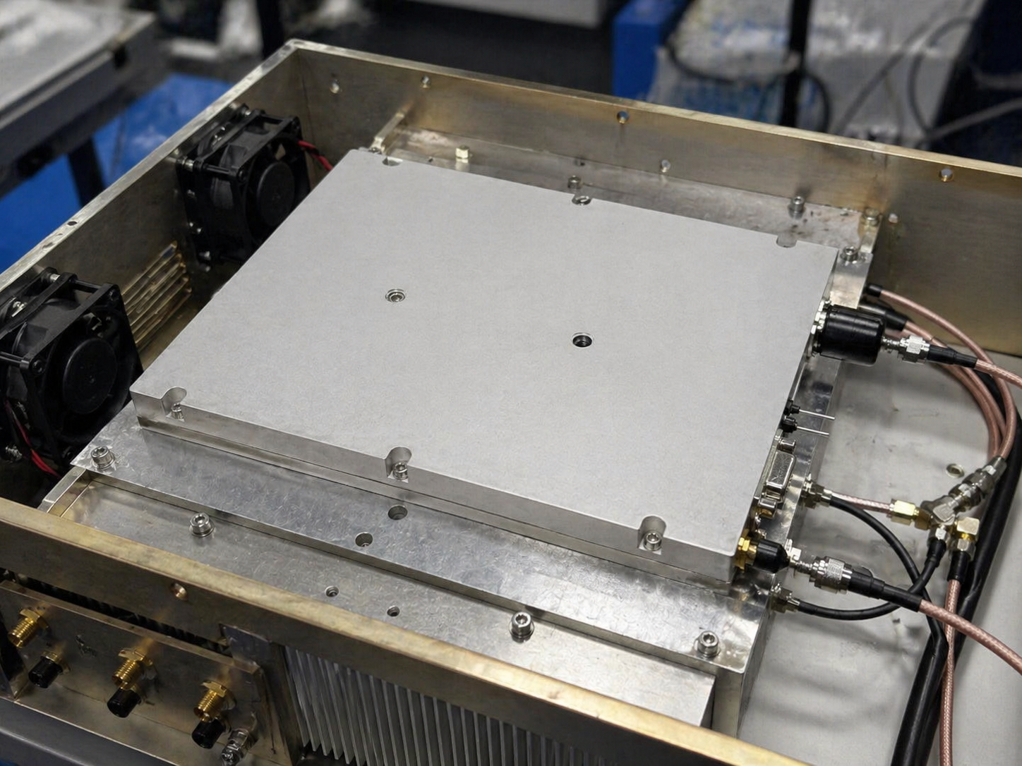
CorelixRF is not only a product supplier. We support RF microwave module development, system-level product manufacturing, micro-assembly, high-frequency testing, CNC mechanical processing, and factory validation for project-specific RF systems.
From RF power amplifier platforms to SDR integration, EMC-oriented systems, rack-mounted systems and high-frequency assemblies, our engineering and production capabilities help customers reduce integration risk and shorten development cycles.
- RF microwave module and system development
- CW and pulse solid-state amplifier manufacturing
- Project-scope RF unit and channel equipment review
- Chip design and die-level test capability
- Micro-assembly and cleanroom process support
- CNC mechanical processing
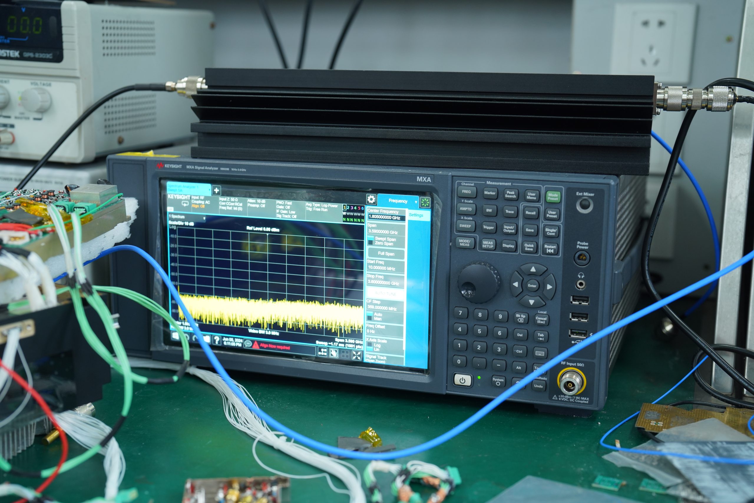
- High-frequency microwave testing capability for applicable project scope
- System-level RF validation
- ISO 9001 & GJB 9001C quality systems

Chip design, RF module development, and system-level engineering handled internally — no third-party outsourcing for core RF design.
Micro-assembly, CNC mechanical processing, and full module and rack system assembly capability in-house.
High-frequency test platforms, noise parameter review, S-parameter verification and active load-pull support for applicable project scope.
ISO 9001 and GJB 9001C certified quality systems applied across RF module manufacturing, assembly, and system validation.
Application Areas for Custom RF Systems
CorelixRF custom RF systems serve engineering teams across test, communications, aerospace, and research sectors.
Custom RF systems for signal amplification, RF output validation, frequency response testing, and broadband test bench development.
RF amplifier systems and test-chain configurations for military, automotive, component-level, and civil EMC applications.
Amplifier, SDR, antenna, and RF chain configurations for broadband communication testing and system development.
RF channel equipment, telemetry paths, tracking-related RF units and related test platforms reviewed by project scope.
Compact RF front-end, amplifier, antenna, and enclosure configurations for platform-level RF payload integration.
RF amplifier and high-frequency microwave configurations for radar front-end testing, RF sensing, and system development.
Custom RF modules, rack systems, chassis-integrated units, and control interfaces for OEM equipment manufacturers.
Flexible RF systems for laboratories requiring custom frequency coverage, signal generation, amplification, and measurement support.
Common Risks When Buying Custom RF Systems
Custom RF systems require more than matching a frequency and output power number. The wrong RF chain, enclosure, cooling method, antenna match, or control interface can create performance and reliability problems after integration.
Output power must be reviewed together with frequency range, gain, input level, load condition, cable loss, antenna handling, and duty cycle.
A module that works on an open bench may behave differently after being installed inside a rack, chassis, or rugged enclosure.
Project-specific systems require engineering support for frequency, power, interface, structure, testing, and troubleshooting.
Remote control, status monitoring, interlock, protection logic, and communication protocol should be reviewed before system design is finalized.
Amplifier and antenna mismatch can increase reflection risk, reduce performance, and create reliability concerns.
Custom RF systems should be verified before shipment to reduce integration risk for system integrators and OEM customers.
Information Needed for Engineering Review
Continue to the Right CorelixRF Platform Path
Use these documented product and platform pages to narrow the starting point before custom RF system review.
SDR / Waveform Path
For RF signal generation, SDR-driven chains and waveform-related review.
RF Amplifier Platform Path
Start from standard, frequency-specific or custom amplifier platforms.
Antenna & Output Path
Review output-side antenna, load and custom antenna requirements.
Custom RF Systems FAQ
Discuss Your Custom RF System Requirement
Share your frequency range, output power, RF chain, interface, enclosure and application environment. CorelixRF will review the closest documented platform path and recommend a custom configuration.
Custom RF System Review Checklist for Serious Buyers
A custom RF system should not start from a vague request for more power. CorelixRF reviews the full operating target first: frequency, waveform, power, duty cycle, enclosure, antenna path, cooling, control interface, documentation and factory acceptance expectations.
Requirement Inputs
- Frequency range and instantaneous bandwidth
- Output power target and duty cycle
- Use case: EMC, SDR, C-UAS, lab or field platform
Engineering Outputs
- Recommended amplifier and signal-chain structure
- Cooling, control and protection assumptions
- Test items needed before shipment
Buyer Confidence
- Factory-direct communication
- Configuration traceability
- Clear path from RFQ to prototype or batch build
| Project stage | What CorelixRF checks | Useful buyer output |
|---|---|---|
| Early RFQ | Band, power, waveform, load, antenna and compliance constraints. | A clearer specification and a realistic system path before quoting. |
| Prototype build | Thermal headroom, VSWR protection, control interface and mechanical fit. | Prototype notes, test assumptions and integration risk list. |
| Pre-shipment | Power, gain, protection behavior, documentation and packing requirements. | Factory acceptance checklist and buyer-side test reference. |