
RF Chain
Wideband RF Transmit Chain
For SDR-driven RF chains, communication platforms, and broadband transmit systems requiring stable RF output across 300–1700 MHz.
Compare CorelixRF 300–1700 MHz RF amplifier modules with 30, 50, 100, 150 and 200 W options. Select a model against your complete operating band and output requirements, then confirm its electrical and integration conditions.
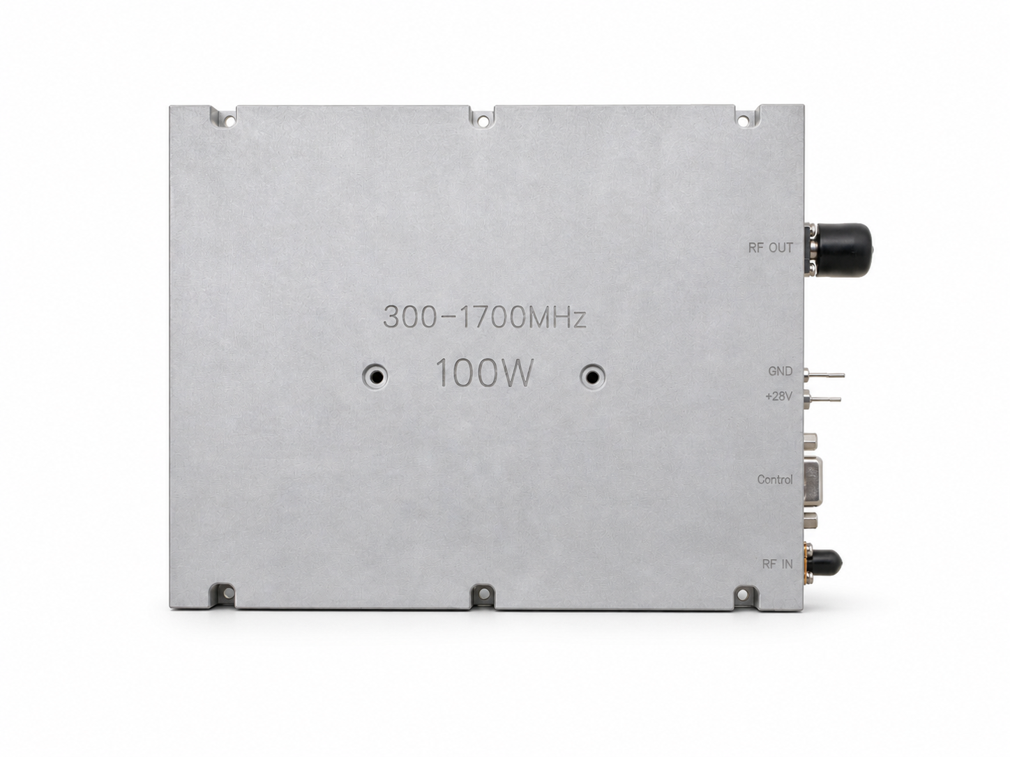
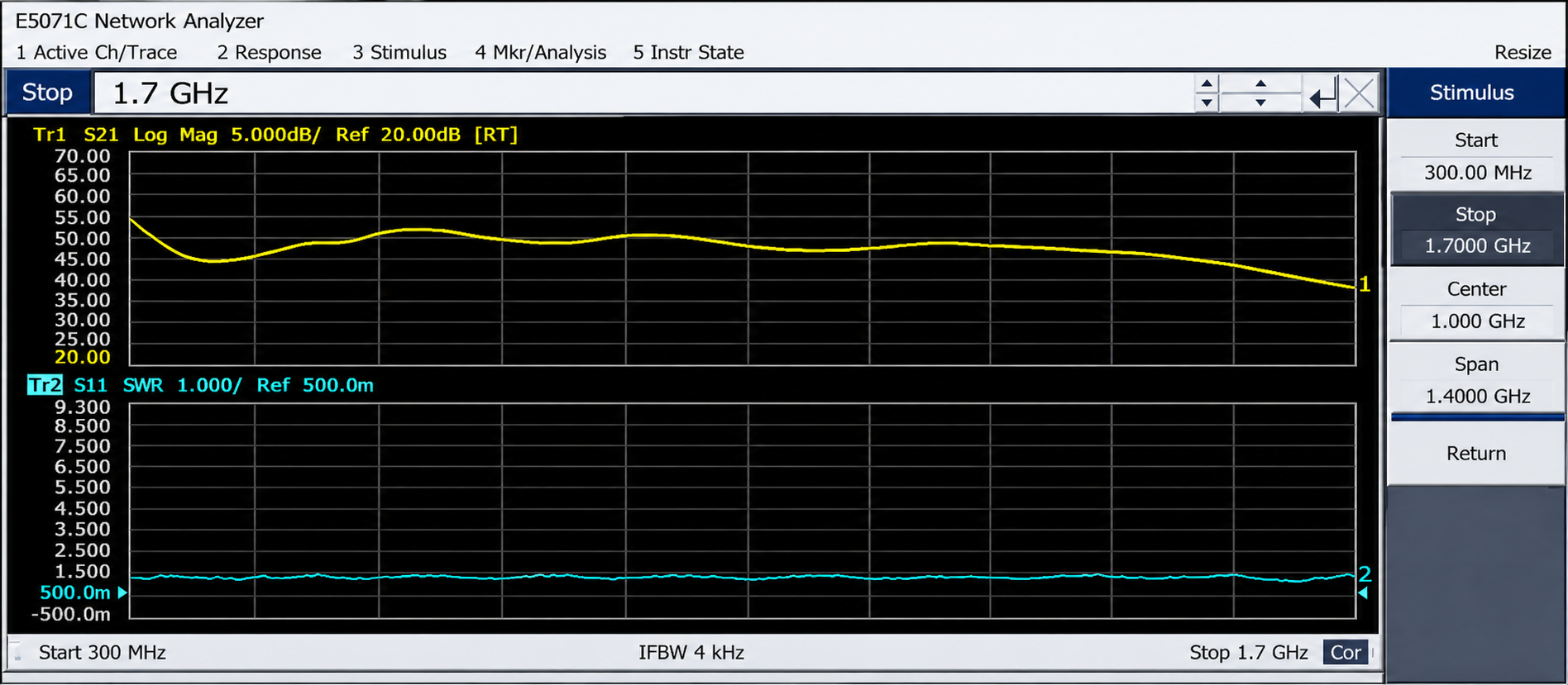
Model-specific datasheet, test curve, and mechanical drawing available after engineering review.
Standard Models
Compare the listed RF power amplifier modules by frequency and output power. For a 50W RF amplifier or 100W RF amplifier requirement, confirm the exact model rating and operating conditions.
Swipe horizontally to compare model specifications.
| Model Number | Frequency | Pout | Typical Gain | Input VSWR | Supply | Size | Best For | Action |
|---|---|---|---|---|---|---|---|---|
| CRF-PA-300M1700M-30W | 300–1700 MHz | 30W | 45 dB Typ. | ≤1.8:1 | 28 VDC | 125 × 59 × 21.5 mm | Driver stage / lab evaluation | |
| CRF-PA-300M1700M-50W | 300–1700 MHz | 50W | 47 dB Typ. | ≤1.8:1 | 28 VDC | 125 × 59 × 21.5 mm | Broadband RF test bench | |
| CRF-PA-300M1700M-100W | 300–1700 MHz | 100W | 50 dB Typ. | ≤1.8:1 | 28 VDC | 200 × 158 × 25 mm | OEM integration projects | |
| CRF-PA-300M1700M-150W | 300–1700 MHz | 150W | 52 dB Typ. | ≤1.8:1 | 28 VDC | 200 × 158 × 25 mm | High-power transmit chain | |
| CRF-PA-300M1700M-200W | 300–1700 MHz | 200W | 53 dB Typ. | ≤1.8:1 | 28 VDC | 200 × 158 × 25 mm | Demanding RF output applications |
Documentation
For qualified projects, CorelixRF can provide model-specific documentation to support RF, mechanical, and system-level evaluation.
Electrical specifications, connector references, operating limits, and test conditions.
Representative gain / frequency curve and model-specific test data available during engineering intake.
Package size, mounting reference, connector position, and integration reference.
Gain, output power, VSWR, and validation data available according to project scope.
Datasheet, test curve, mechanical drawing, and unit validation data are handled through engineering intake. Contact engineering →
Application Fit
When comparing UHF RF power amplifier options, check the full operating range rather than a single frequency point. Confirm output, gain, supply and cooling conditions for the selected 300–1700 MHz model.
For SDR-driven RF chains, communication platforms, and broadband transmit systems requiring stable RF output across 300–1700 MHz.
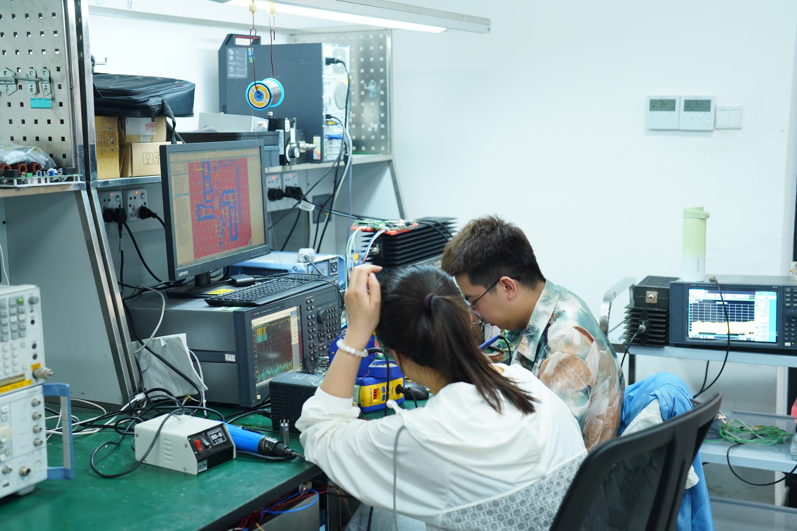
Supports antenna testing, component validation, EMC pre-compliance, and laboratory RF output evaluation.
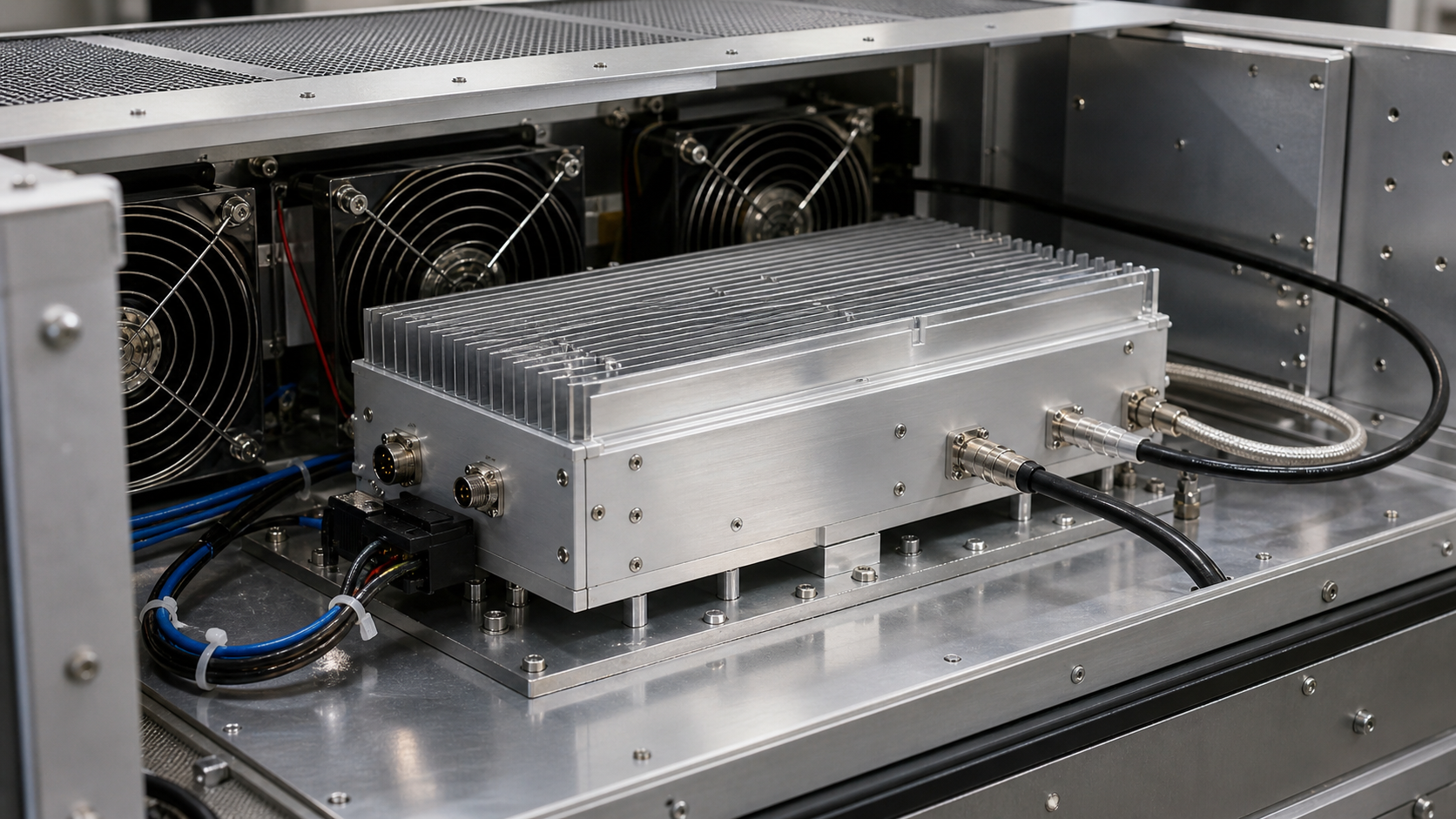
Module-level RF power stage for integrators who need mechanical drawings, connector references, and thermal review support.

For wideband RF chain evaluation where stable power, cooling design, and protection behavior must be reviewed before deployment.
OEM Integration
We help buyers reduce engineering uncertainty before quotation, production, and system-level integration.
Direct RF engineering review before quotation, covering frequency range, output power, drive level, operating mode, and system constraints.
Standard 300–1700 MHz models are available, with sub-band optimization for flatter gain or improved efficiency when required.
Gain, output power, input VSWR, and related RF validation data can be provided according to project scope.
Mechanical outline, connector reference, cooling method, and enclosure integration details can be reviewed for OEM projects.
Factory Evidence
Real production and validation evidence helps buyers confirm factory capability before cooperation. Each shipment can be supported with project-defined RF validation records and integration documentation when required.
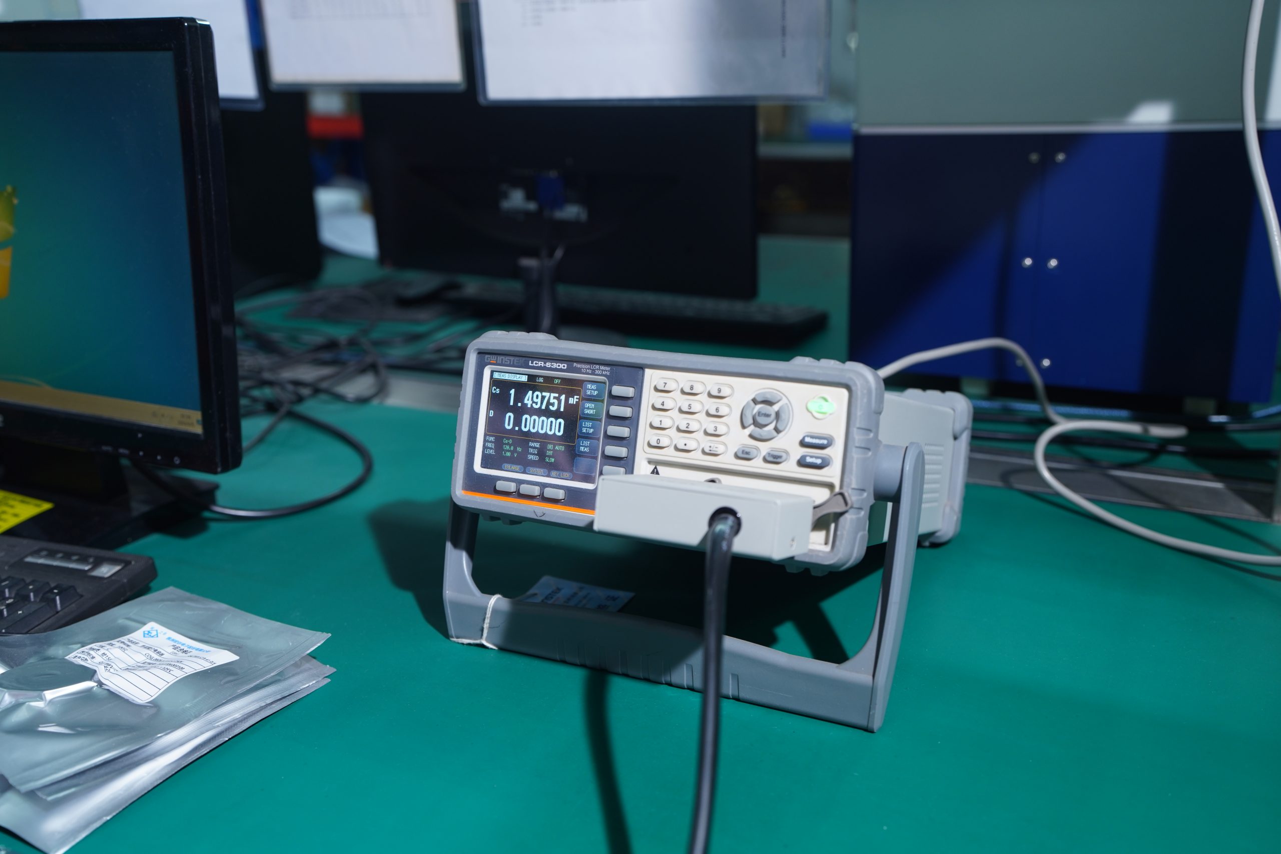
Gain, output power, and VSWR checks before shipment.
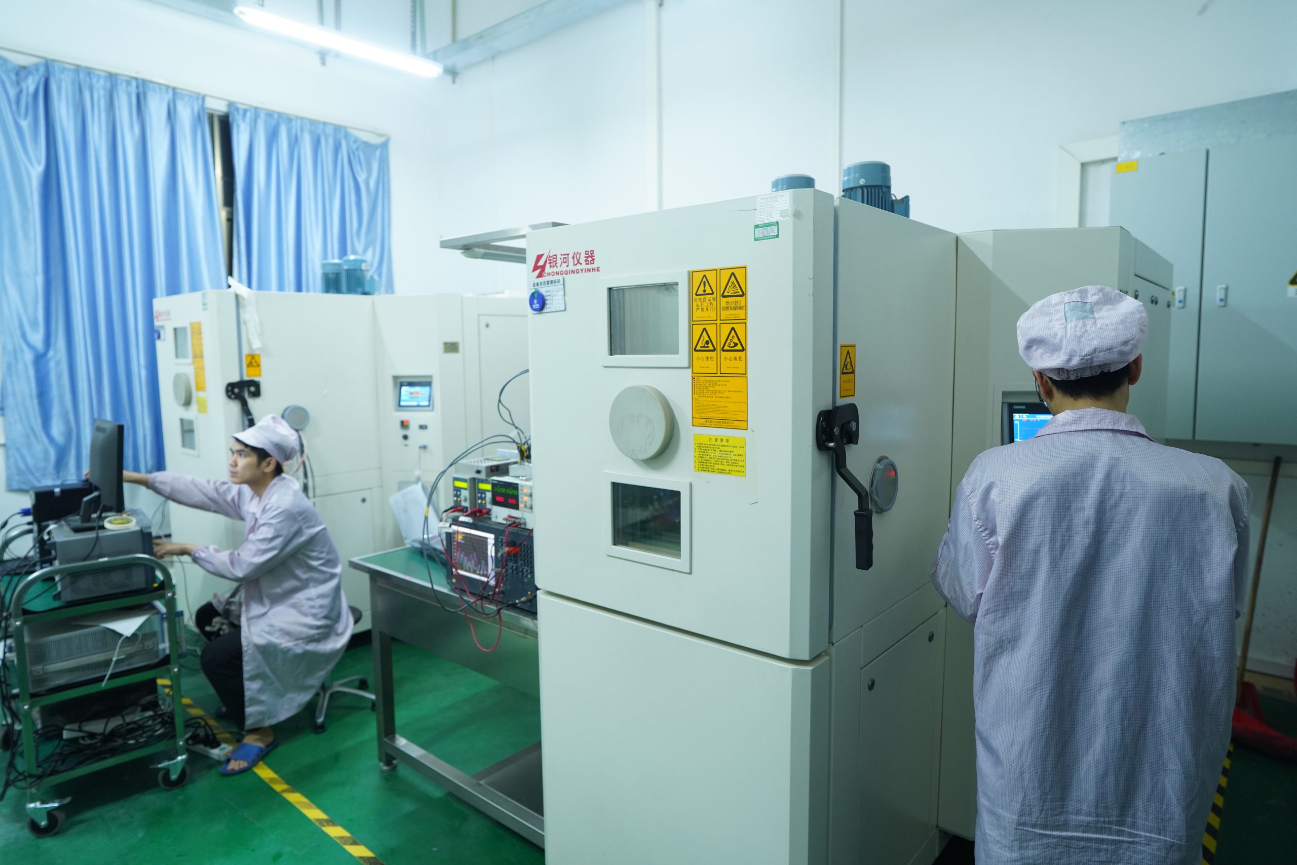
Thermal behavior reviewed under defined operating conditions.
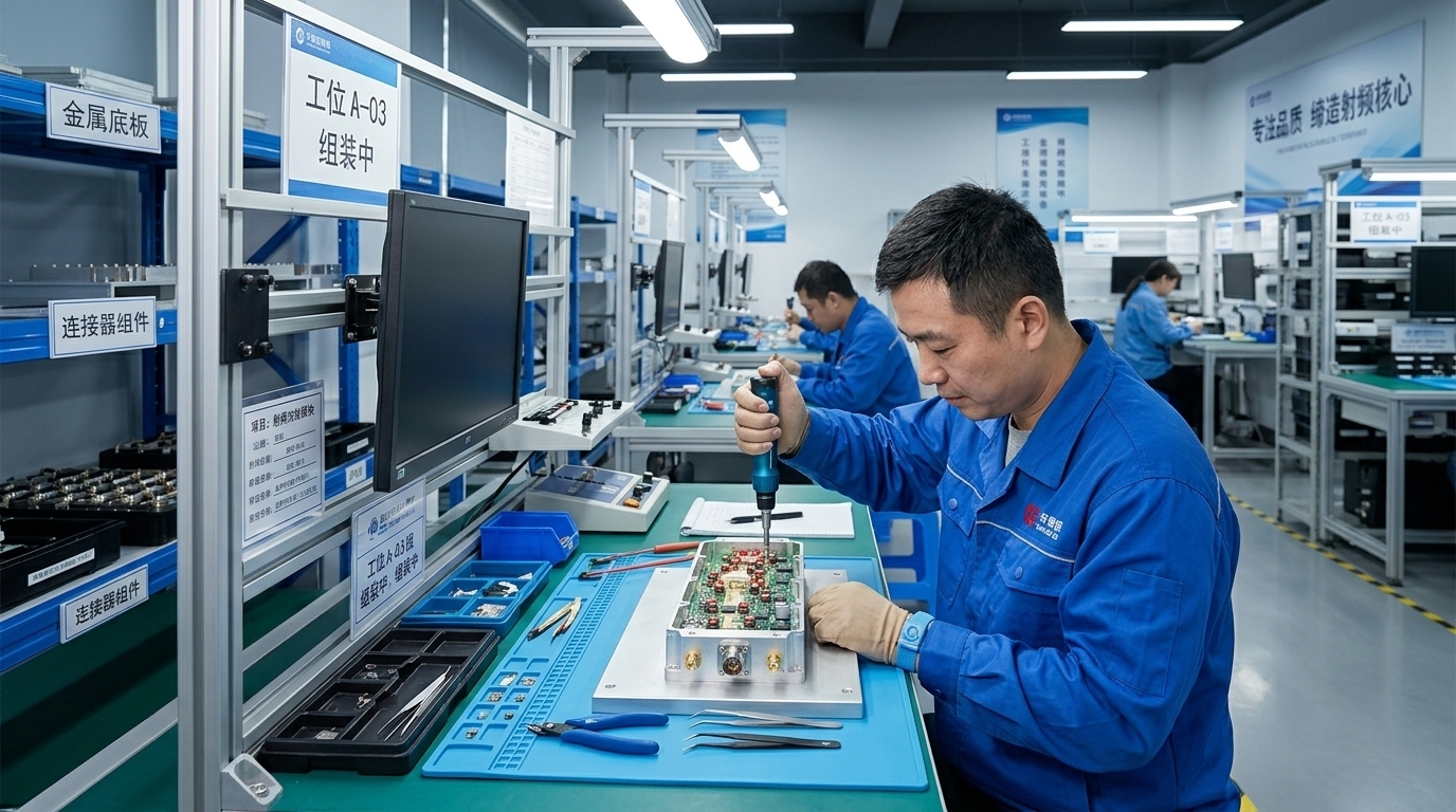
In-house RF assembly and process control for production consistency.
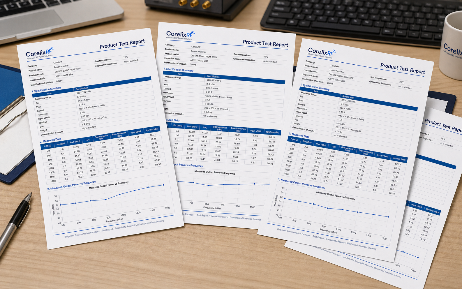
Test reports, traceability records, and mechanical interface drawings confirmed during engineering intake.
To speed up engineering review, please prepare the following information.
FAQ
Common technical and procurement questions before selecting a 300–1700 MHz RF power amplifier.
Typical input drive for rated output is 0 to 8 dBm under datasheet test conditions. The exact drive margin should be confirmed per model and operating condition.
Start with your complete operating frequency range. Then compare model-specific output, gain, supply, cooling and mechanical requirements. A broader frequency range does not automatically mean better performance.
As an engineering recommendation, plan current headroom above maximum rated draw according to operating mode, compression target, and thermal environment.
Standard models use air cooling. Enclosure airflow, mounting surface, and ambient conditions should be reviewed during engineering intake.
Standard RF connectors are SMA-Female input and N-Female output. Alternative connector configurations and mounting details can be reviewed for OEM projects.
Gain, output power, input VSWR, and related RF validation data are available according to project scope and confirmed during technical intake.
RF amplifier price depends on the selected model, configuration and quantity. Include your full frequency range, output requirement, operating conditions, integration needs and required documentation when requesting a quotation.
Yes. NDA support is available before deeper technical discussions or sharing application-specific mechanical, electrical, or integration information.
Engineering Intake
Send your operating requirements. Our engineering team will review frequency range, output power, input drive level, operating mode, cooling method, documentation scope, and quotation details before reply.
Start with the required full-band output, then confirm input drive, gain flatness, supply current, cooling, load condition and integration space before model selection.
Evaluate these classes for SDR-driven RF chains, laboratory output stages and compact OEM platforms where lower power and smaller mechanics are preferred.
The datasheet-supported 100W platform is a practical starting point for UHF/L-band communication, antenna validation, RF testing and OEM integration.
Higher-output projects require closer review of current headroom, airflow, mounting, VSWR protection and full-band performance before quotation.
Compare 300–1700 MHz when your complete operating band is within that range, and review 300–2700 MHz when coverage above 1700 MHz is required. Frequency coverage alone does not establish gain, efficiency or linearity; compare the exact model specifications.
| Selection Factor | 300–1700 MHz | 300–2700 MHz |
|---|---|---|
| Frequency direction | UHF to L-band | UHF to lower S-band |
| Best starting point | Projects that do not require 1.7–2.7 GHz coverage | Projects requiring wider continuous frequency coverage |
| Engineering review | Confirm full-band power, gain flatness, input drive, interface, cooling, load and mechanical limits. | |