01 // EMC TESTING
EMC Testing & Radiated Immunity
For EMC labs and pre-compliance test setups requiring stable VHF/UHF RF output across low-frequency bands.
EMC TestingRadiated ImmunityPre-Compliance
Factory-Direct VHF/UHF RF Power Amplifier Platform
Factory-direct 30W to 200W RF power amplifier platforms for EMC testing, VHF/UHF communication test benches, broadband RF chains, and OEM low-band RF system integration.
Best-Fit Applications
This platform is designed for VHF/UHF projects where broadband RF output, practical integration, and engineering documentation are required before quotation or system deployment.
01 // EMC TESTING
For EMC labs and pre-compliance test setups requiring stable VHF/UHF RF output across low-frequency bands.
02 // COMMUNICATION
For engineering teams validating VHF/UHF communication links, antenna matching, RF front-end behavior, and broadband transmit chains.
03 // RF LAB
For lab environments requiring repeatable RF output, gain verification, cable-loss review, and 50Ω load testing.
04 // OEM
For system integrators who need module-level RF power stages with 28VDC supply, air cooling, connector review, and mechanical integration support.
Standard Platform Selection
Select a power class first. Detailed RF data, measured curves, current consumption, VSWR reference, and mechanical drawings can be provided after project requirement review.
Swipe table horizontally on mobile
| Model | Frequency | Power Class | Platform | Best-Fit Use | Action |
|---|---|---|---|---|---|
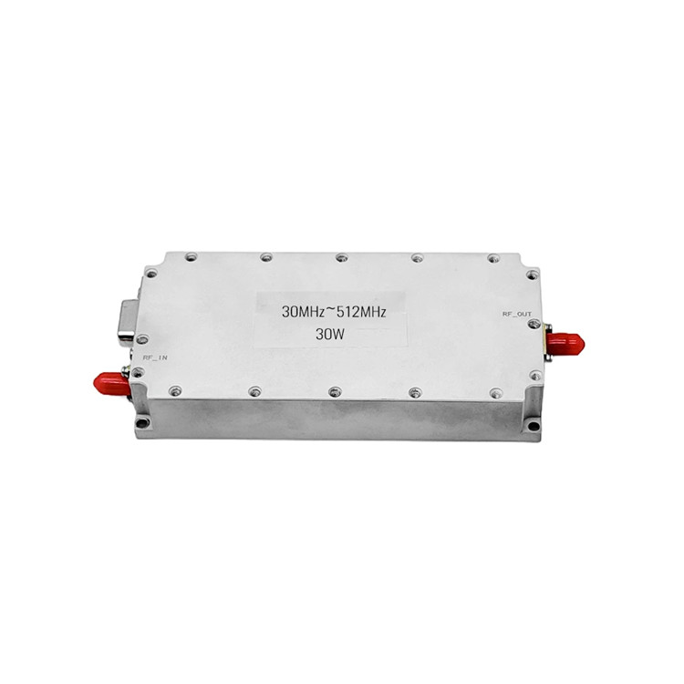
| CRF-PA-30M512M-30W | 30–512 MHz | 30W | Compact air-cooled module | Lab evaluation / low-power RF bench | |
| CRF-PA-30M512M-50W | 30–512 MHz | 50W | Compact air-cooled module | EMC pre-compliance / VHF-UHF testing | |
| CRF-PA-30M512M-100W | 30–512 MHz | 100W | High-power air-cooled module | RF test bench / OEM integration | |
| CRF-PA-30M512M-150W | 30–512 MHz | 150W | High-power air-cooled module | Higher-power VHF/UHF RF chain | |
| CRF-PA-30M512M-200W | 30–512 MHz | 200W | High-power air-cooled module | Broadband RF system validation | |
| Custom Sub-Band | Project-defined | By review | OEM / ODM configuration | Sub-band, connector, cooling, mechanical review | Send Requirement |
Typical RF Chain
A 30–512 MHz amplifier should be selected together with input drive level, gain budget, cable loss, output filtering, antenna/load VSWR, duty cycle, and cooling condition. CorelixRF reviews these RF chain conditions before recommending a standard model or custom sub-band configuration.
Engineering Data
To avoid wrong model selection and protect project-specific RF data, CorelixRF provides detailed documents after reviewing the customer’s frequency range, power level, operating mode, and integration conditions.
Model-level datasheet can be provided after requirement confirmation.
Gain behavior, output power reference, matching reference, and related RF data can be shared for engineering review.
Mechanical outline and connector layout can be provided for integration review.
Sample test report format and validation scope can be discussed according to project stage.
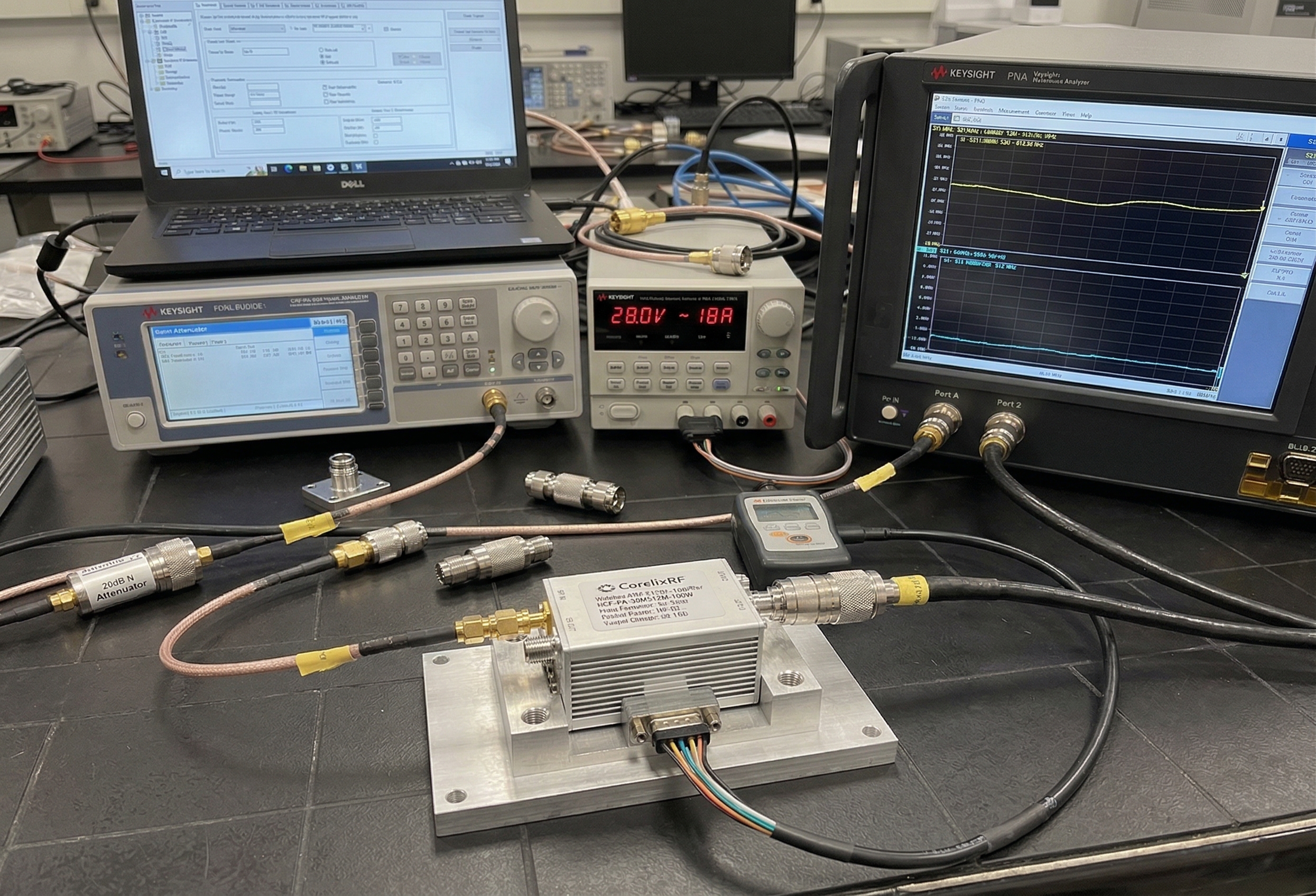
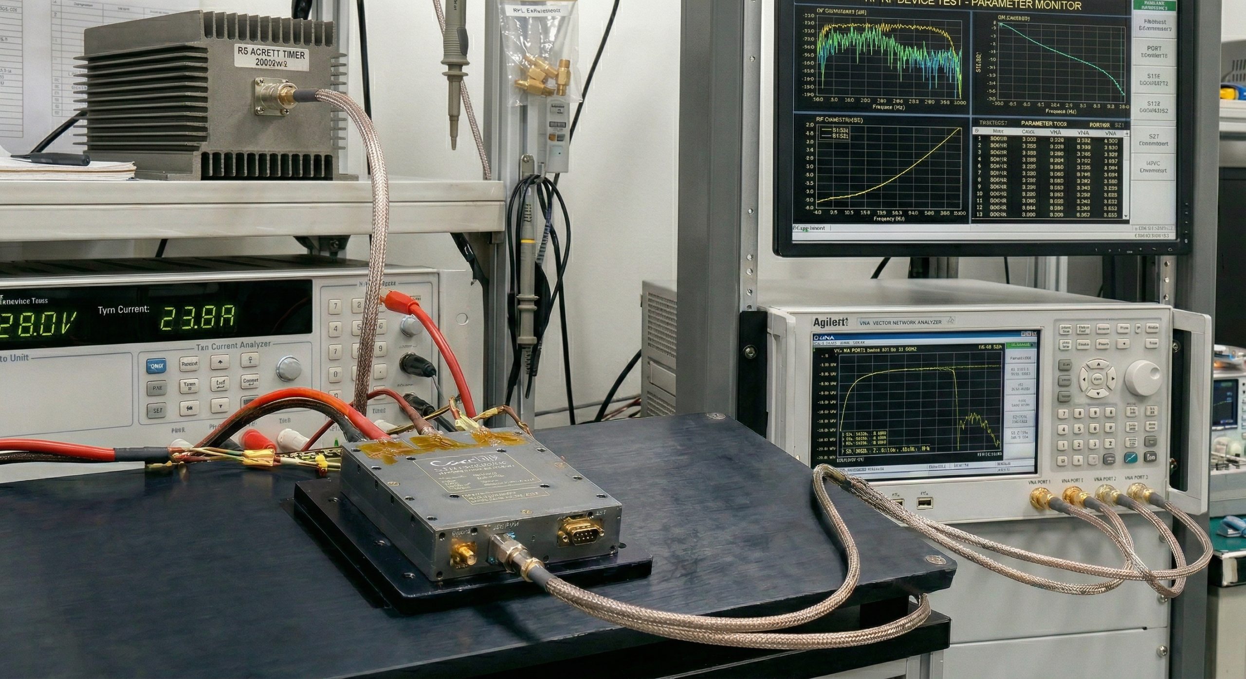
RF Test Bench
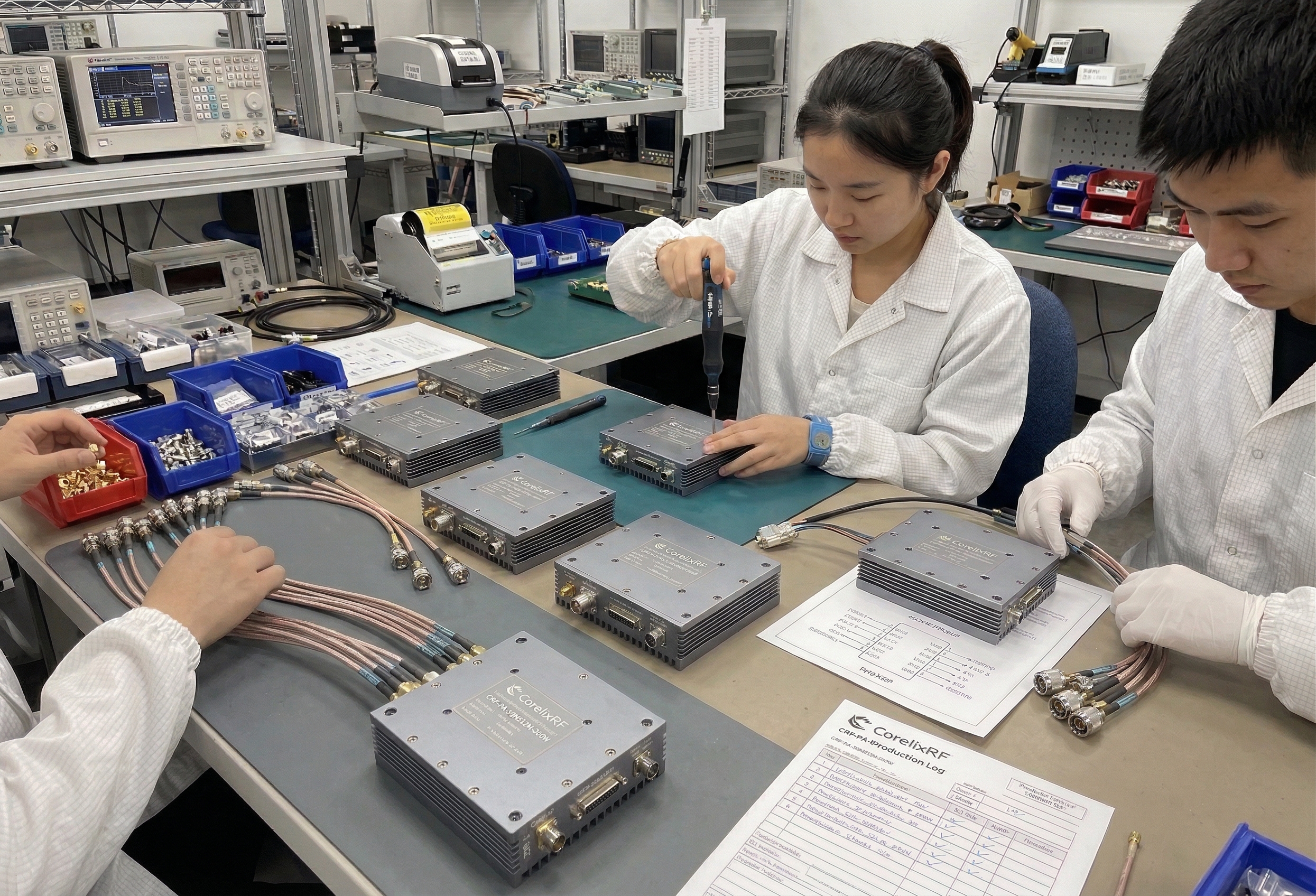
Factory Validation
Engineering Support
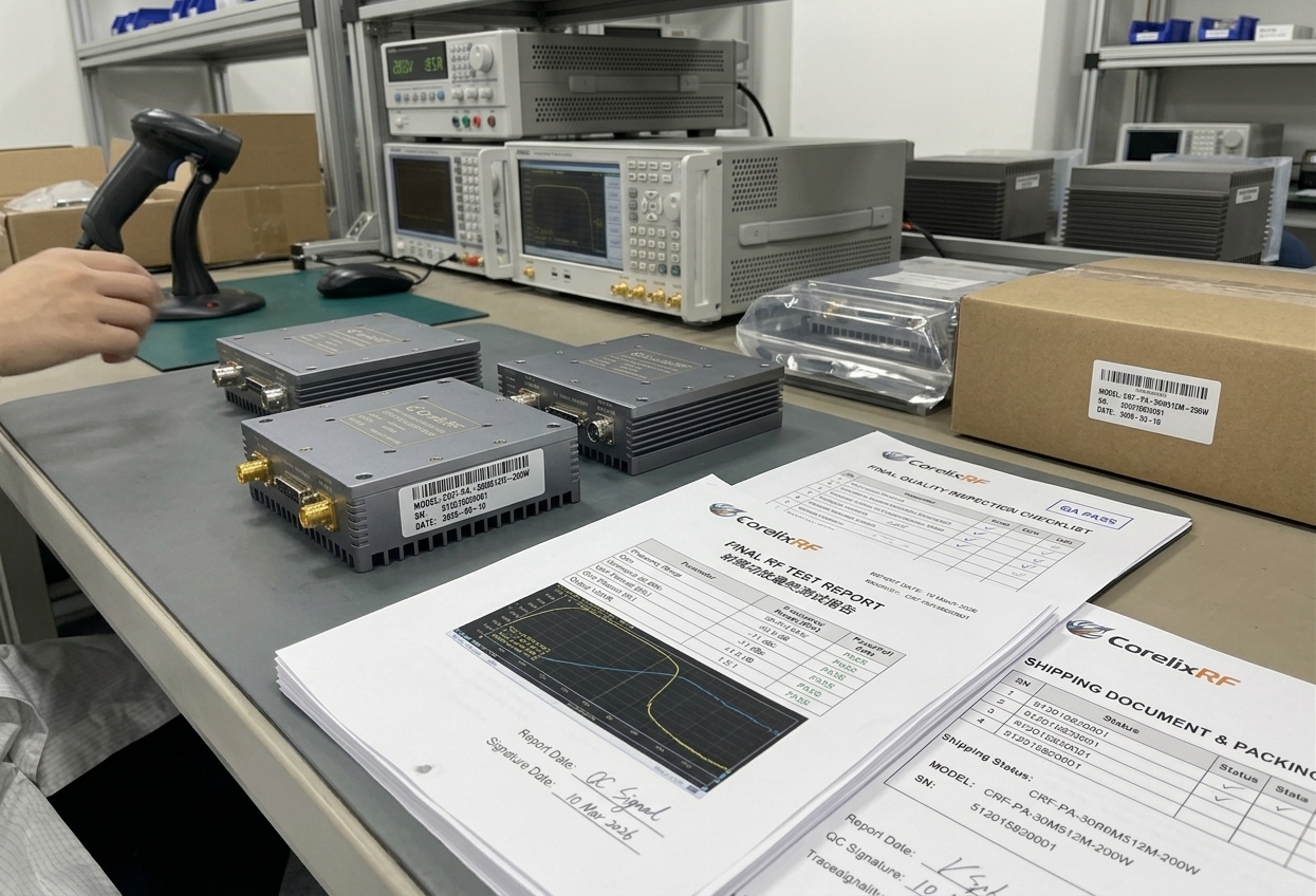
Integration Review
Standard or Custom
Not every project requires full 30–512 MHz coverage. CorelixRF can review whether a standard power class or a custom sub-band configuration is more suitable for the actual RF chain.
FAQ
Engineering questions that help customers decide whether to request datasheet, test data, mechanical references, or a custom sub-band review.
Yes. This platform can be reviewed for EMC test benches and pre-compliance setups where stable VHF/UHF RF output is required. Final selection should consider antenna gain, cable loss, duty cycle, load condition, and required field strength.
Selection should start from required output power, operating mode, input signal level, cooling condition, and integration space. CorelixRF can review your RF chain before recommending a standard model.
Detailed RF data, measured curves, current reference, VSWR reference, and mechanical drawings are provided after requirement review to ensure accurate model matching and protect project-specific technical information.
Yes. If your actual operating band is narrower than 30–512 MHz, CorelixRF can review a custom sub-band configuration for system integration.
Yes. Please send your frequency range, output power, application, operating mode, and project stage. The relevant datasheet and available engineering data can be provided for review.
Yes. OEM requirements such as connector layout, control interface, cooling method, mechanical fit, and custom frequency range can be reviewed before quotation.
Please send frequency range, output power, CW or pulse operation, input signal level, supply voltage, cooling method, antenna or load condition, connector requirement, quantity, and project stage.
Mechanical references can be provided after requirement review, especially for OEM integration and system layout confirmation.
RFQ Intake
To recommend the right standard model or custom sub-band configuration, please share your RF chain and integration conditions.
Use the RFQ form or datasheet request form to receive the right model-level information. Detailed parameters are shared after requirement review instead of being fully published on this page.