SDR Only
Review Broadband SDR Generator
For teams first checking the 100 MHz–6 GHz SDR source module, RS422 control and board-level OEM format.
View SDR Generator →Factory-direct SDR source modules matched with CW RF power amplifier platforms. CorelixRF reviews SDR output level, amplifier input requirement, frequency overlap, control interface, connector path and system integration before recommendation.
CW matching scope: this page focuses on SDR source modules matched with CW amplifier platforms only. Pulsed RF amplifier projects are reviewed separately because pulse width, duty cycle, pulse frequency and timing behavior require a different engineering path.
Use this page as the bridge between SDR source selection, CW amplifier matching, antenna/load/DUT review and custom RF chain integration.
For teams first checking the 100 MHz–6 GHz SDR source module, RS422 control and board-level OEM format.
View SDR Generator →For projects that need SDR output level, CW amplifier input, frequency overlap and power class reviewed together.
Go to Matching Paths →For RF chains where the amplifier output drives an antenna and needs power handling, VSWR and connector review.
View Wideband Antenna Path →For OEM integration, connector/control customization, enclosure format or project-specific output-side conditions.
Start Engineering Review →Most RF integration problems don't come from bad components — they come from components that were never designed to work together.
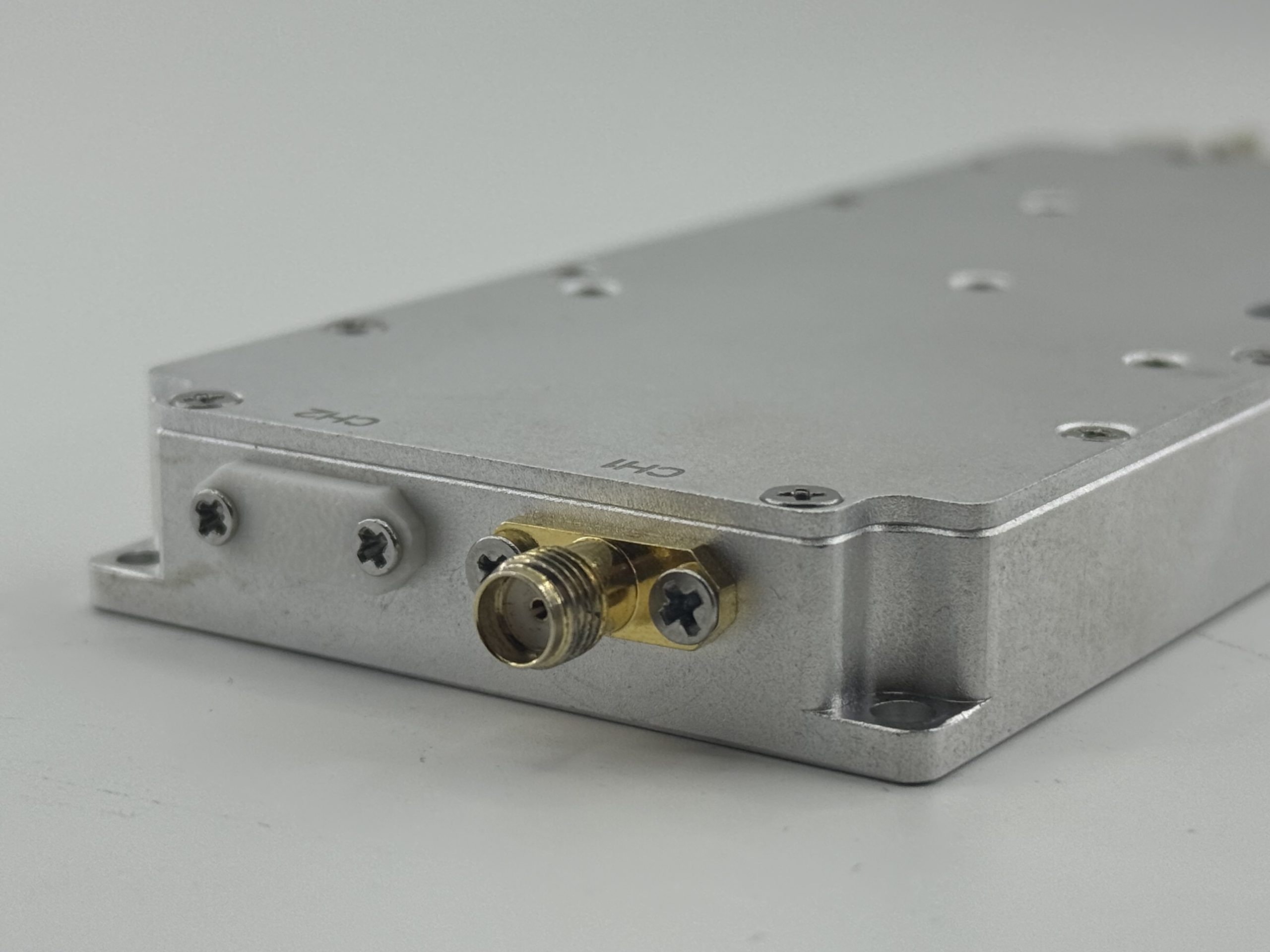
We manufacture both the SDR source module and the RF power amplifier platforms — in the same factory, with the same engineering team responsible for the full chain.
A complete SDR + amplifier signal chain isn't two products placed side by side. It's a matched path where source output, amplifier input sensitivity, frequency range, and interface logic are all aligned from the start.
One supplier. One matched system. Complete support from signal source to amplified output.
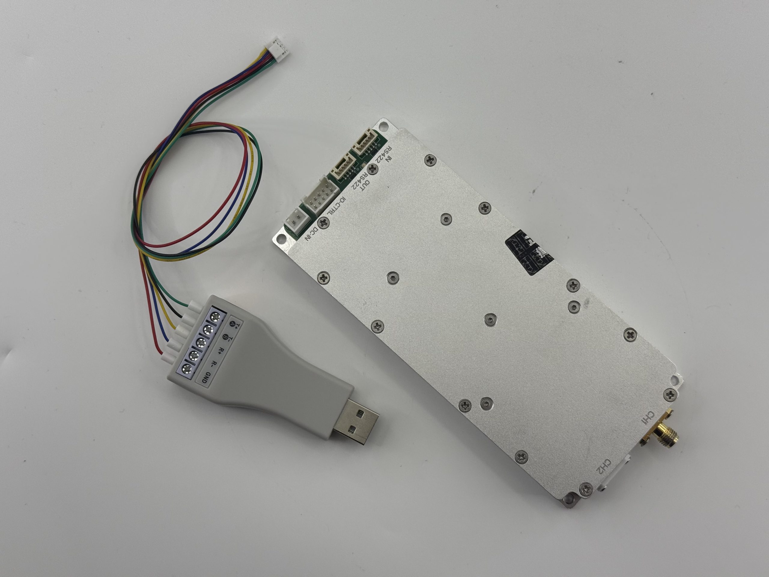
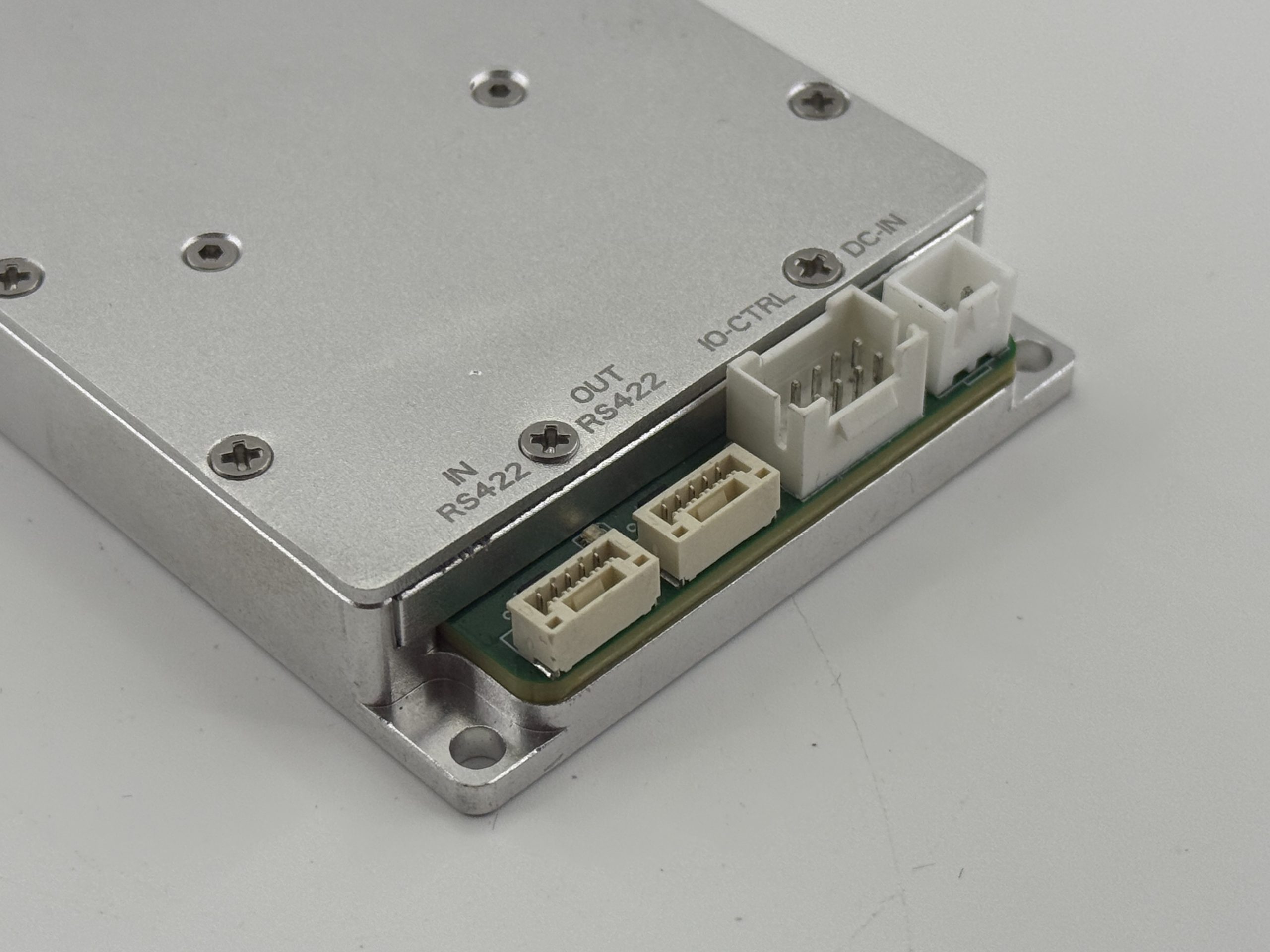
100 MHz–6 GHz, 200 MHz real-time bandwidth. Board-level compact format with RS422 control, SMA output, and 9–32 VDC supply. Designed for bench and embedded integration.
View SDR GeneratorCW amplifier platform paths: 30–512 MHz, 300–1700 MHz, 300–2700 MHz and 2–6 GHz. Selected by SDR frequency overlap, amplifier input requirement and output power class.
View RF Power Amplifier PlatformsCorelixRF reviews SDR output level, amplifier input requirement, connector path, control interface, power supply and system-level RF output before recommendation.
Request Matching ReviewA purpose-designed RF source module for engineering work. In this page, the SDR source is matched with CW amplifier platforms based on frequency overlap, SDR output level, amplifier input requirement, control interface and connector path.
SDR + amplifier system matching is based on CW amplifier platforms only. The final working range is not a catalog band claim — it is confirmed by the overlap between the 100 MHz–6 GHz SDR source and the selected CW amplifier platform.
Stable lower-band CW amplification for communication evaluation, RF test chain setup and compact platform integration. For SDR-driven use, the effective matched range starts from the SDR overlap section.
Broad mid-band CW coverage for communication validation, subsystem integration and SDR-driven development projects from UHF through L-band.
Wider CW platform coverage for multi-band SDR-driven RF chain needs, reducing the number of amplifier families required across a project.
High-frequency CW front-end development and RF testing where wideband S to C-band coverage matters. Strongest match for SDR source projects in the 2–6 GHz range.
A working SDR + amplifier chain is not only about frequency overlap. SDR output level, amplifier input requirement, control interface, connector path, power supply and RF validation should be reviewed together.
The SDR output level must be suitable for the amplifier input requirement. Too low may not drive the amplifier properly; too high may require attenuation or protection.
SDR coverage and amplifier band must overlap across the actual working frequency range, not only in a broad catalog description.
This matching path is based on CW amplifier platforms. Pulsed RF amplifiers require a separate pulse engineering review.
RS422, remote control, software commands and amplifier control logic should be reviewed together before integration.
SMA, N-type, cable length and RF loss affect the final signal path from SDR source to amplifier output.
Testing the SDR and amplifier as a signal chain is more useful than reviewing two separate datasheets.
Send the details below and CorelixRF will review the suitable SDR source, CW amplifier platform path and RF integration requirements.
Whether you need a bench configuration, an embedded subsystem, or a full RF front-end path — CorelixRF supports all three from the same factory engineering team.
SDR + amplifier configured for signal generation and path validation. Fast deployment for RF verification without managing multiple vendor chains.
Configure Lab Setup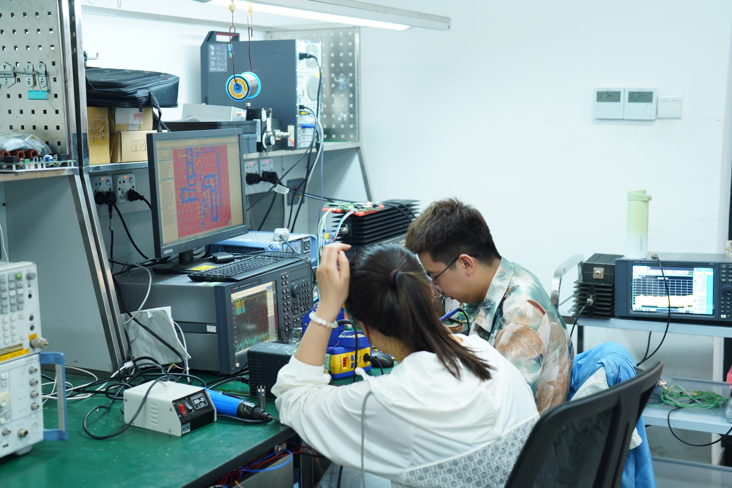
Board-level and module-level integration for customers building SDR + amplifier functions into their own equipment. One engineering team owns the full interface review.
Explore OEM Options
Combined source + amplification paths for front-end platform design. Full engineering coordination from source module to amplifier output — mechanical, electrical, and interface.
Start Project ReviewStandard SDR and CW amplifier platforms are the starting point. When your project needs a custom waveform, output power class, connector path, control interface, power supply or enclosure format, our factory engineering team reviews the full signal chain.
Start from standard, move into custom only where needed. Our engineering team owns both paths.
SDR + amplifier combinations suited for development, integration, and validation across a range of RF engineering contexts.
Controlled source generation and amplifier-assisted path validation for RF test environments and signal chain verification.
Development and evaluation tasks requiring stable frequency coverage and consistent output power across test cycles.
Embedding matched SDR source and amplifier modules into customer platforms and subsystems with full engineering support.
Coordinated source, amplification, and interface engineering for teams building RF transmit-side or front-end system paths.
This section clarifies what happens after the CW amplifier output. The output can be an antenna, RF load, attenuator path, chamber input, DUT or OEM RF port — and each condition changes the matching review.
The SDR + CW amplifier chain should not be reviewed without the output-side condition. The same SDR and amplifier platform can behave differently when connected to an antenna, dummy load, attenuator, chamber input or customer DUT.
CorelixRF reviews the real output path together with SDR output level, CW amplifier input requirement, connector type, cable path, impedance and power handling.
When the output is an antenna, CorelixRF reviews antenna frequency coverage, power handling, impedance, connector type, cable loss and radiation-path requirements before recommendation.
View Omnidirectional Antenna Path →For laboratory validation, the SDR + CW amplifier chain can be reviewed with dummy load, attenuator, coupler, chamber input or other controlled RF test conditions.
Explore CW Amplifier Platforms →For OEM integration, the output may connect to a customer-defined RF port, DUT or subsystem. Mechanical layout, RF connector and control interface are reviewed together.
Ask Custom RF Chain Review →The output-side condition affects delivered RF power, stability and integration risk. These items are reviewed before confirming the SDR + CW amplifier chain.
The difference isn't just about supplier count. It's about who owns the system chain — and who you call when something doesn't work.
We manufacture both the SDR module and the RF power amplifier platforms in-house. The engineering team that designs your component is the same team that validates your system chain.
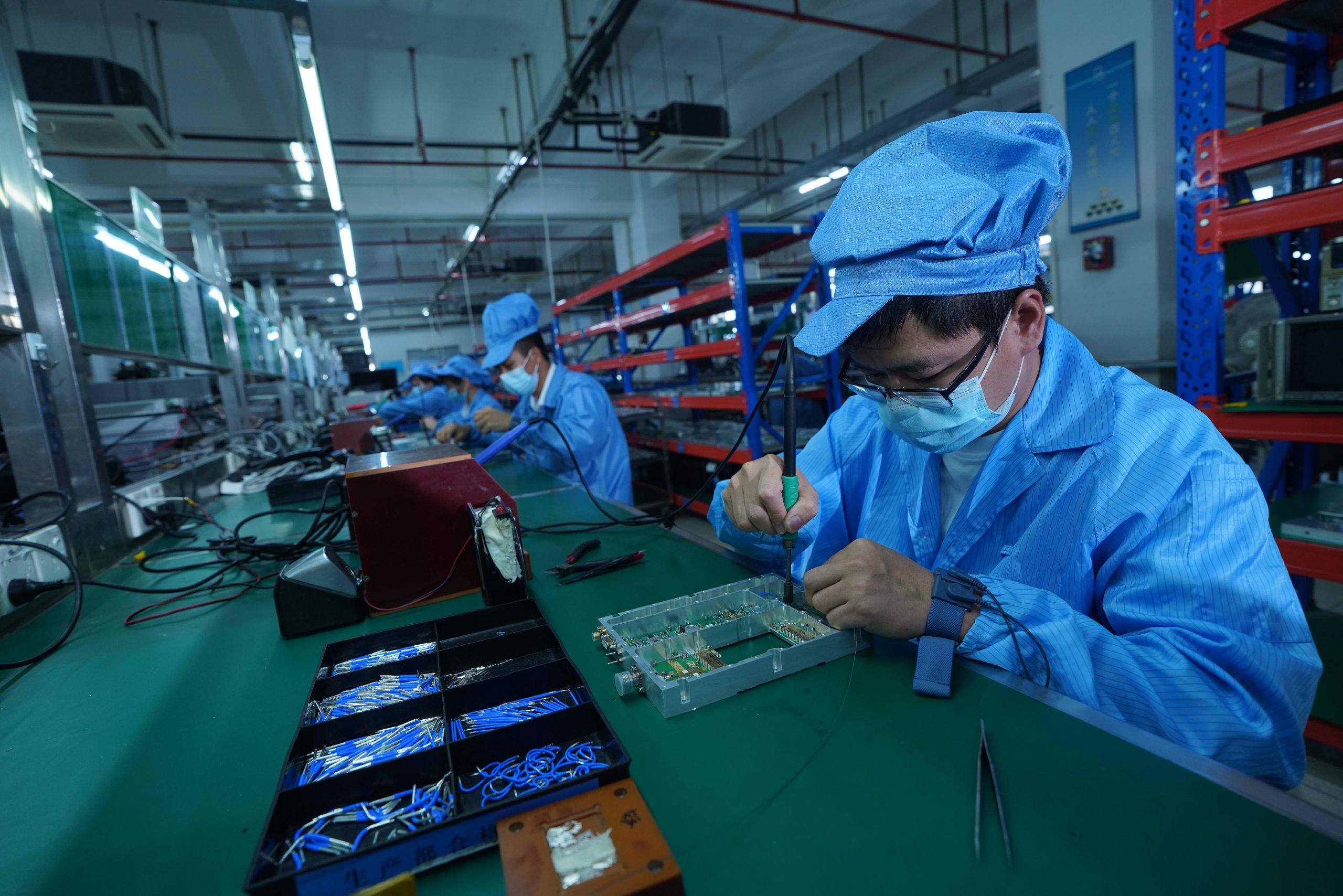
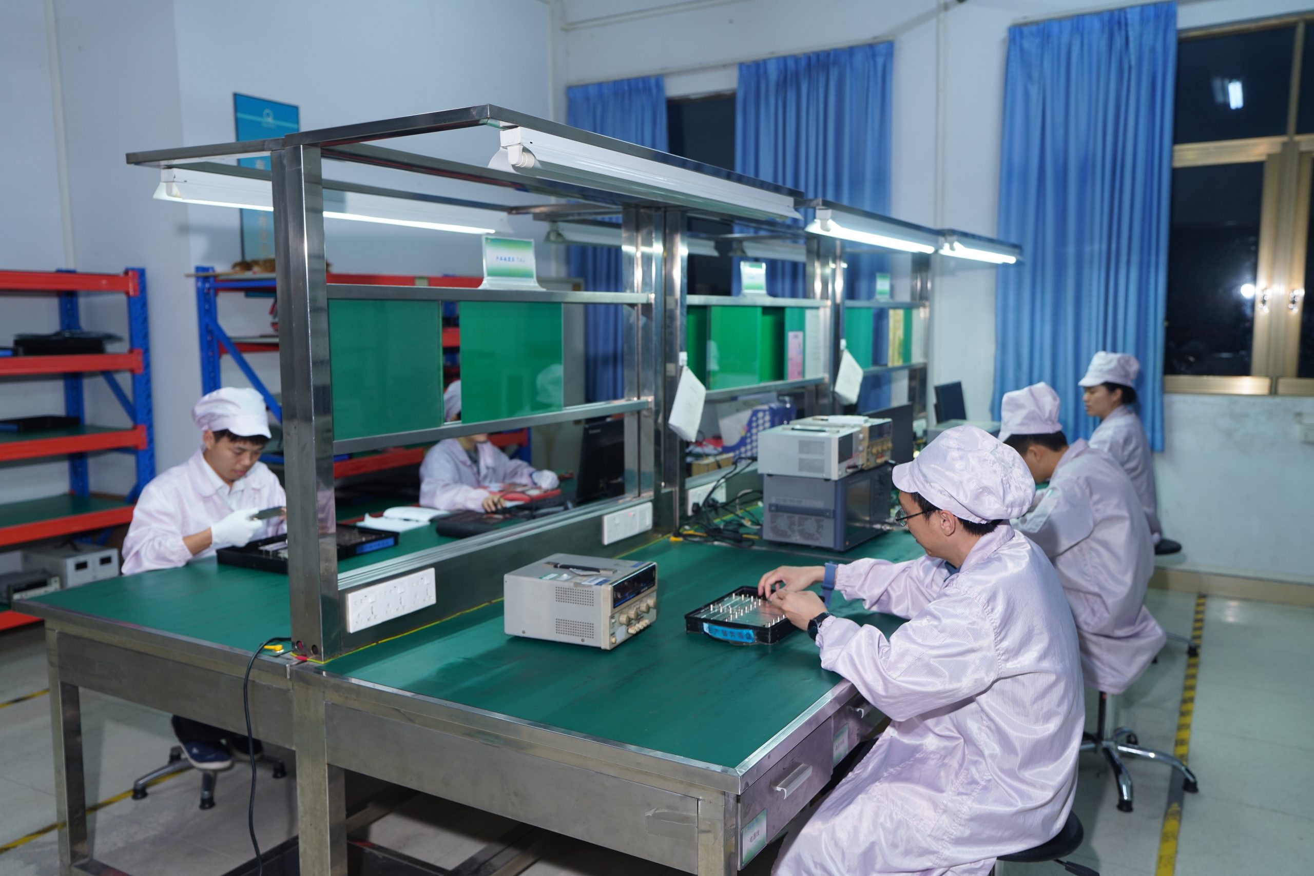
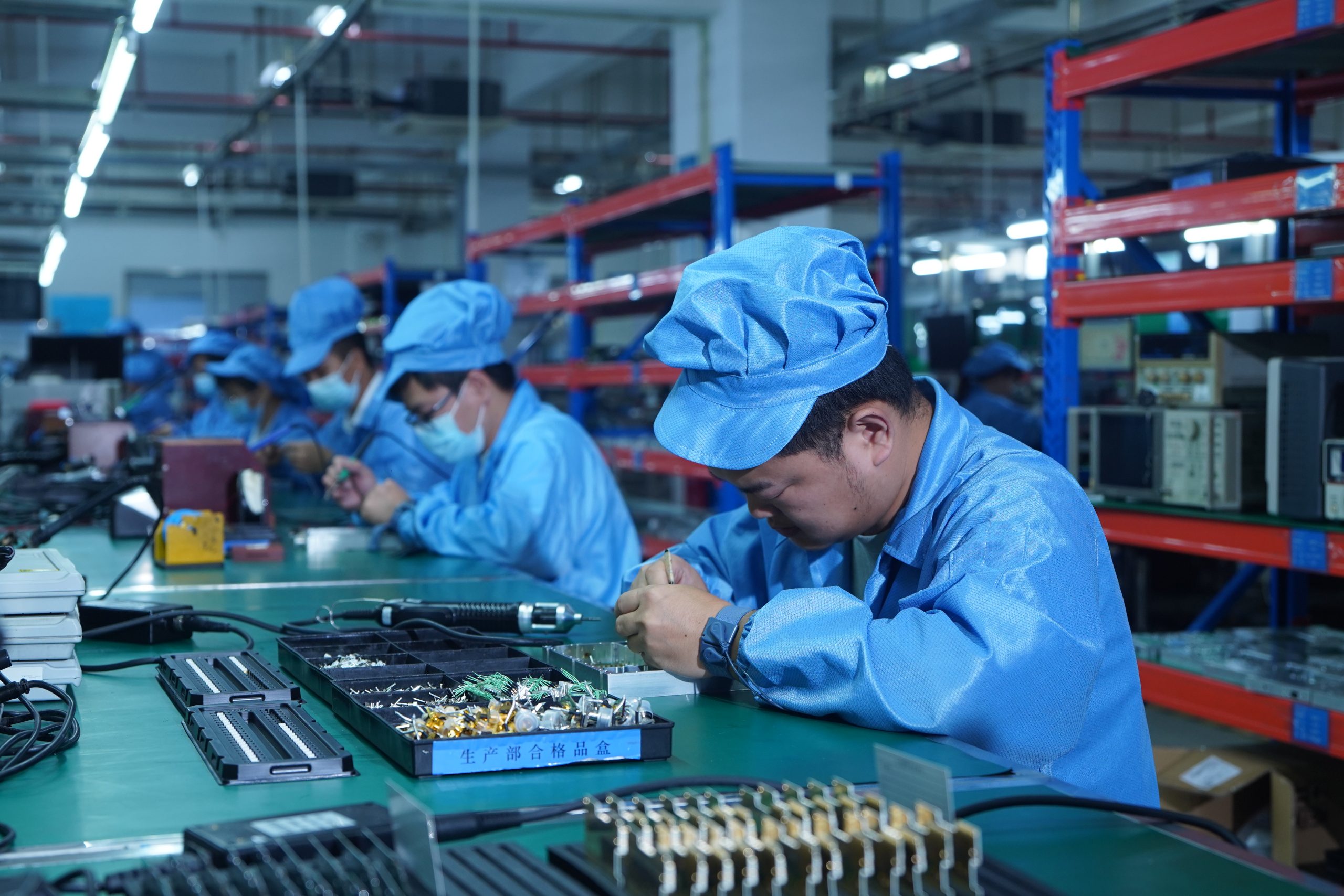
Our in-house capabilities include component modeling, chip design, micro-assembly, CNC machining, and full RF module and system development. When you submit a requirement, you're engaging a factory engineering team — not a sales desk.
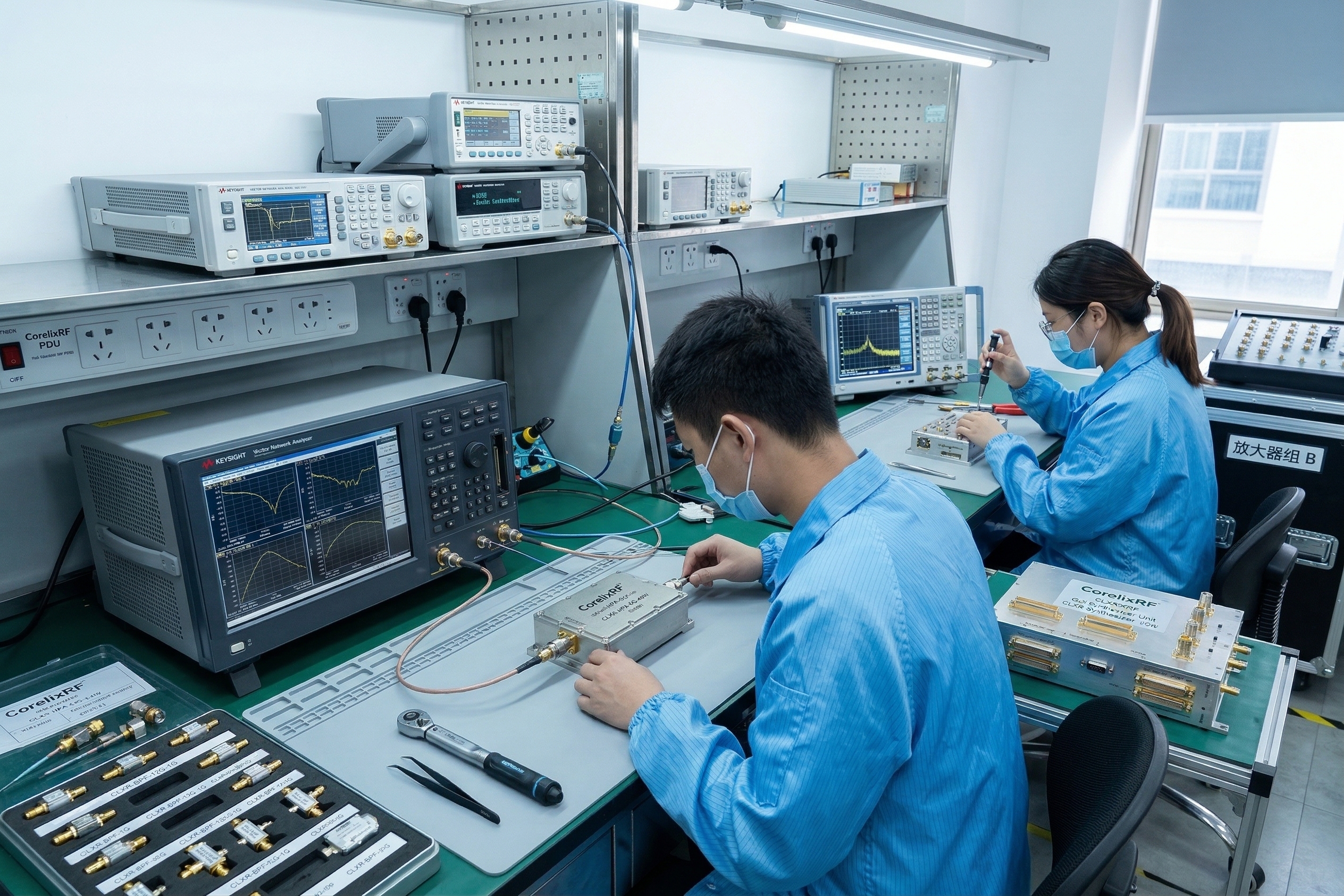
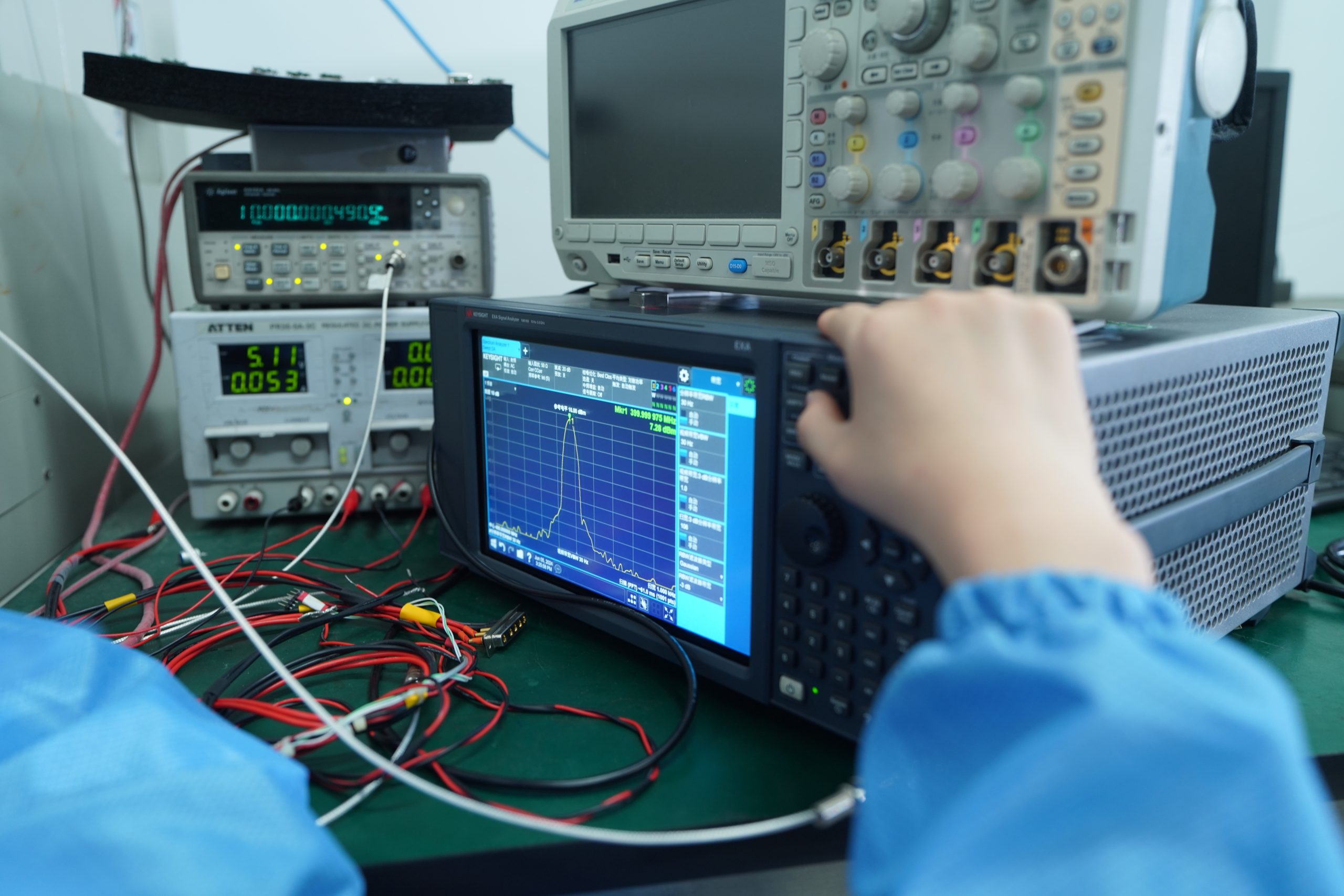
8 dedicated test laboratories and more than 1,400 on-site test instruments give us the ability to validate complete SDR + amplifier signal chains before they reach your facility. That's a capability most distributors cannot offer — because they don't build what they sell.
SDR modules and RF amplifier platforms manufactured in-house. No intermediaries. Faster coordination and direct engineering ownership.
Start from standard platforms. Move to custom engineering only where needed — same team, not a separate department.
Four standard amplifier platforms cover all major integration bands. SDR source spans the full 100 MHz – 6 GHz range.
In-house test capability for system-level signal chain validation. Validated performance before delivery — not just spec sheets.
Chip design, component modeling, micro-assembly, and full system development under one roof. Your 48-hour review is handled by engineers, not sales staff.
ISO 9001 and GJB 9001C certified. Full OEM and ODM support for customers who need more than catalog part procurement.
Four steps from requirement submission to matched solution — no lengthy RFQ process, no distributor delays.
Frequency range, output power, integration mode, interface needs, and mechanical constraints. Use the form below.
CorelixRF reviews SDR source coverage, CW amplifier platform fit, input level, frequency overlap and output-side condition.
Connector path, control interface, power supply, thermal condition and mechanical format are confirmed before recommendation.
Receive a recommended standard platform, customized configuration or full RF chain review path based on project requirements.
Send your target frequency, signal type, required CW output power, SDR output level, connector preference, control interface and integration format. CorelixRF will review the suitable SDR + CW amplifier system path for your project.
Your submission goes directly to our RF engineering team. Within 48 hours for applicable projects, you receive a matched SDR + CW amplifier platform recommendation — not a generic catalog response.