CorelixRF — Source Factory · Custom mmWave Engineering · In-House RF Review
18–40 GHz RF Power Amplifiers
Standard and custom mmWave amplifier platforms for 18–40 GHz RF systems.
CorelixRF provides factory-direct 18–40 GHz mmWave RF power amplifiers with standard 5W, 20W, 40W and 70W model classes, plus project-based customization for frequency window, output power, RF connector, waveguide output, control interface, rack structure and cooling design.
18–40 GHz
Broadband Coverage
5 W–70 W
Output Power Range
37–55 dB
Gain Range
168
R&D Engineers
1,400+
Test Instruments
ISO 9001
GJB 9001C Certified
Selection Guide
Before You Select an 18–40 GHz RF Power Amplifier
At mmWave frequencies, output power is only one part of the decision. Connector loss, waveguide transition, cooling, gain flatness, test setup and control interface can all affect real system performance.
Confirm these items before quotation so the amplifier fits the real RF chain, rack structure and measurement environment.
Full-Band Power Behavior
Headline power does not show how output behaves across the full 18–40 GHz band.
Connector / Waveguide Path
mmWave connector transitions can change delivered power and system margin.
Measurement Setup Loss
Cable, adapter and load conditions matter more at K / Ka-band frequencies.
Rack and Cooling Fit
3U, 4U and 8U formats affect cabinet planning, airflow and installation space.
Control Interface
Remote operation depends on command, interface and system automation requirements.
Data Before Ordering
Integration review often needs datasheets, measured data and engineering notes.
Request Data Review →Core Specifications
Key Specifications for the CRF-PA-18000M40000M Series
A quick engineering overview of the 18–40 GHz standard model classes and configurable areas before reviewing the full model range.
Frequency Range
18–40 GHz
Standard Power Classes
5W / 20W / 40W / 70W
Gain Range
37–55 dB, depending on model
RF Input
2.92 mm-F
RF Output
2.92 mm-F for lower-power model, WRD180 for higher-power models
Package
19" 3U / 4U / 8U
Control Interface
RS485 / LAN / GPIB options
Custom Options
Frequency window, connector, waveguide, control, chassis and cooling review
Final gain, connector, rack height, cooling structure and control interface may vary by power class or custom requirement. Project-level confirmation is recommended before quotation or integration.
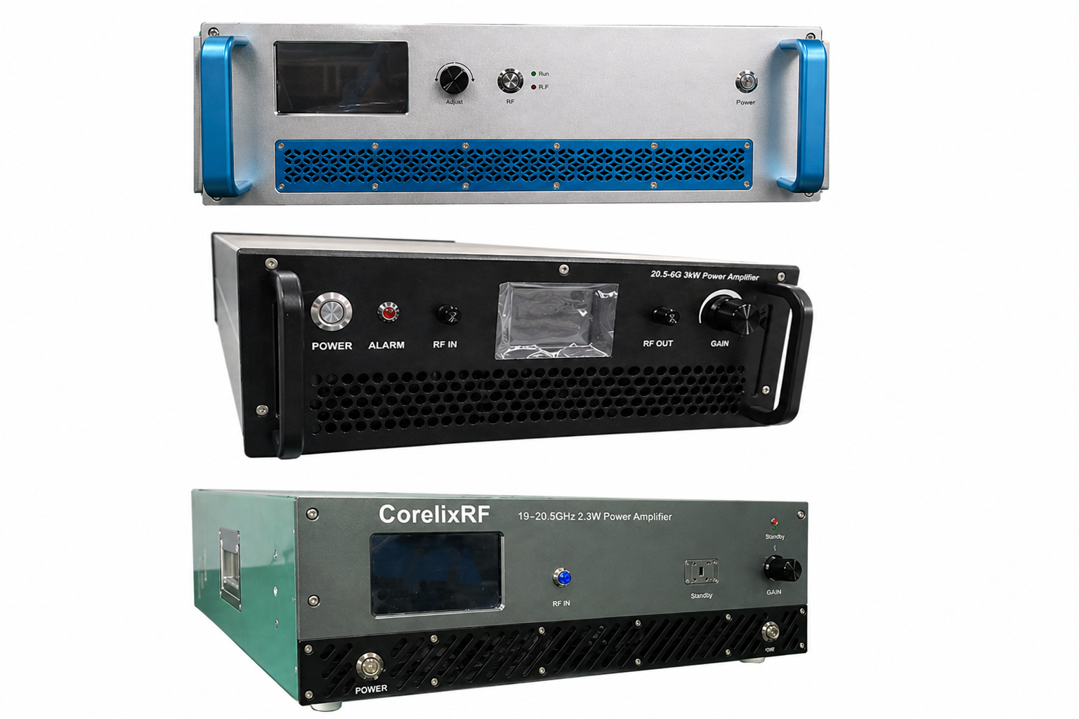
Product Series
Standard 18–40 GHz Model Range for Engineering Review
These standard model classes provide a baseline for 18–40 GHz project review. Final frequency window, connector, waveguide output, rack format, cooling method and control interface can be reviewed for project-specific requirements.
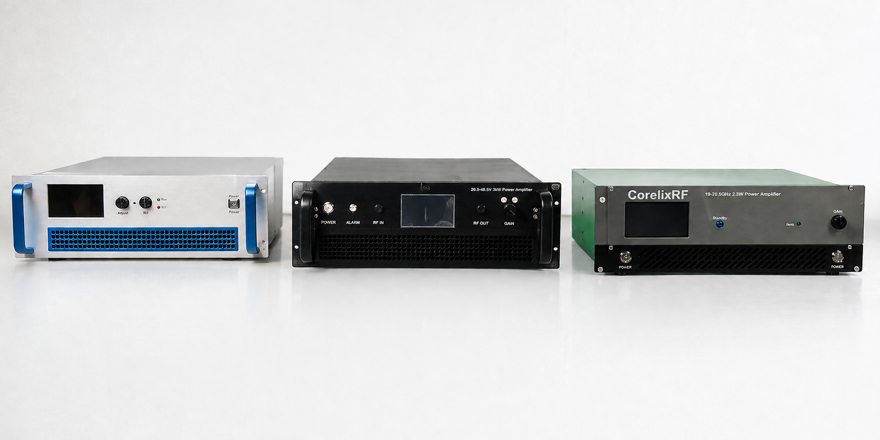 // 18–40 GHz Rack-Mounted mmWave Amplifier Series
Swipe or scroll horizontally to compare power class, gain, connector, rack size and best-fit application.
| Model Number | Frequency | Output Power | Gain | RF Output | Enclosure | Best-Fit Use | Data Request |
|---|---|---|---|---|---|---|---|
| CRF-PA-18000M40000M-5W | 18–40 GHz | 5W | 37 dB | 2.92 mm-F | 19", 3U | Compact lab testing, low-power integration and driver-stage validation. | Request Data |
| CRF-PA-18000M40000M-20W | 18–40 GHz | 20W | 43 dB | WRD180 | 19", 3U | mmWave communication testing, medium-power RF validation and broadband RF chain evaluation. | Request Data |
| CRF-PA-18000M40000M-40W | 18–40 GHz | 40W | 50 dB | WRD180 | 19", 4U | RF test platforms, radar front-end validation, communication testing and system integration. | Request Data |
| CRF-PA-18000M40000M-70W | 18–40 GHz | 70W | 49 dB | WRD180 | 19", 8U | High-power mmWave test systems, rack-mounted RF platforms and demanding integration projects. | Request Data |
Need a different frequency window, connector, control method or rack format?
Use the standard classes as the starting point, then request custom engineering review.
Custom Higher-Power Path
Custom Higher-Power Options for Focused mmWave Bands
When full 18–40 GHz broadband coverage is not required, CorelixRF can review higher-power amplifier configurations for focused mmWave frequency windows such as 18–26.5 GHz. These options are handled as project-specific amplifier configurations rather than the standard full-band 18–40 GHz model range.
// COMPACT CUSTOM REVIEW
5W / 10W
Focused mmWave band · connector review
For compact RF integration, driver-stage validation or test platforms where full 18–40 GHz coverage is not required.
PROJECT-SPECIFIC REVIEW// MID-POWER CUSTOM REVIEW
25W / 40W / 50W
Focused band · waveguide output review
For RF bench platforms, signal-chain validation and focused-band system testing with project-level connector and cooling review.
FOCUSED BAND OPTIONS// HIGH-POWER CUSTOM REVIEW
100W / 200W
Focused mmWave band · rack system review
For higher-power programs that use a narrower frequency window and require engineering confirmation for cooling, enclosure, output path and measurement conditions.
CUSTOM HIGH-POWER PATHFactory Testing
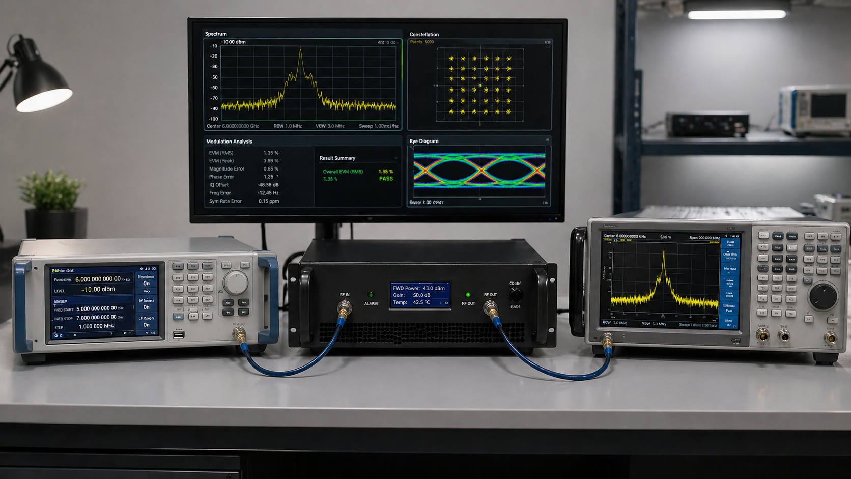
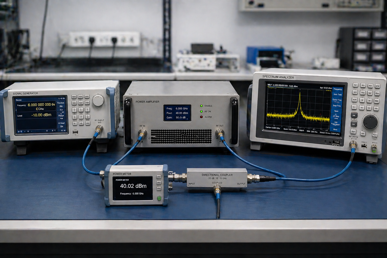
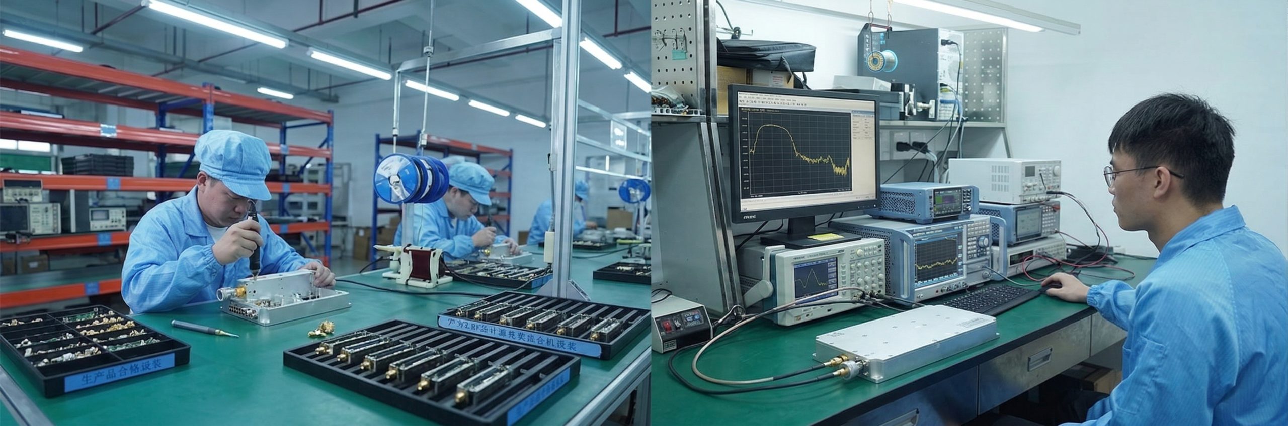
Factory Testing and Engineering Evidence
For 18–40 GHz mmWave amplifier projects, CorelixRF focuses on engineering evidence that helps buyers confirm power behavior, connector path, rack integration and measured RF performance before shipment.
Output Power Review
Power class and frequency-window behavior reviewed against project requirements.
Gain / Flatness Verification
Gain behavior and broadband response checked for integration review where applicable.
VSWR / Connector Check
2.92 mm or waveguide output path reviewed to reduce mismatch and setup risk.
Harmonics / Spurious Observation
Spectrum behavior and unwanted emission references can be reviewed for qualified projects.
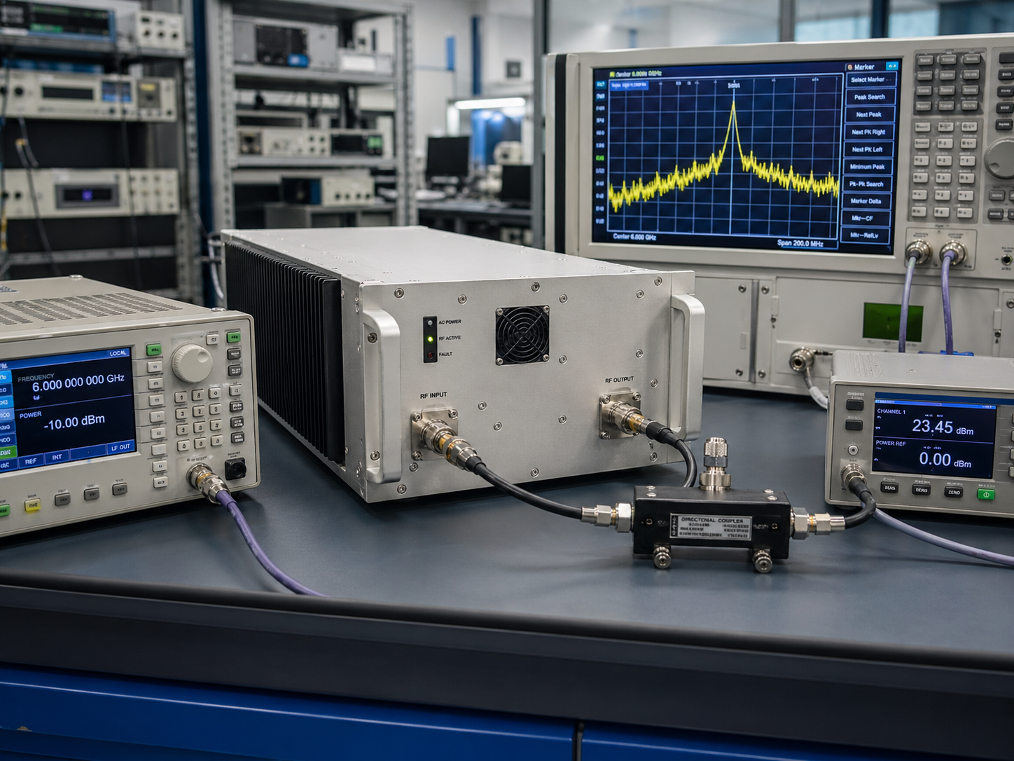
RF Performance Data
Datasheet and measured references for output power, gain, VSWR, harmonics or spurious behavior where available.
Integration Documentation
Connector, control interface, rack format and mechanical details for system-level review.
Project Confirmation Notes
Engineering notes covering custom frequency windows, cooling path or special interface requirements.
Requirement and Configuration Review
Frequency, power, connector, control and rack requirements are checked before build or quotation.
RF Assembly and Connector Inspection
Connector, waveguide and mechanical path are reviewed before RF testing.
Output Power and Gain Verification
Power and gain behavior are checked against the agreed configuration.
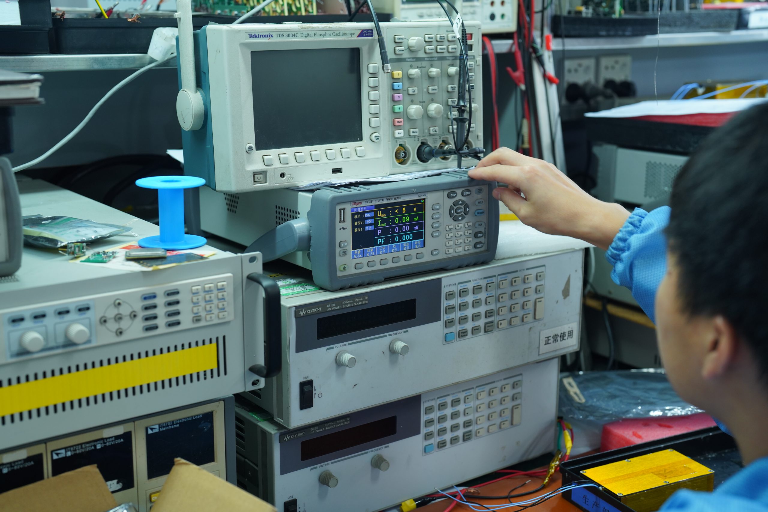
VSWR / Protection / Control Response
Matching, protection and remote control functions are reviewed as required.
Thermal and Rack Airflow Review
Rack height, airflow and high-power thermal conditions are considered before delivery.
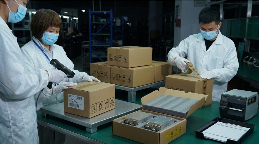
Test Record and Packing Confirmation
Relevant records, documentation and packing checks support export delivery and integration review.
Typical Applications
Application-Oriented RF Power Amplifier Use Cases
In high-frequency RF systems, the amplifier is not only a power component — it determines signal reach, link budget, test repeatability, and system-level RF performance.
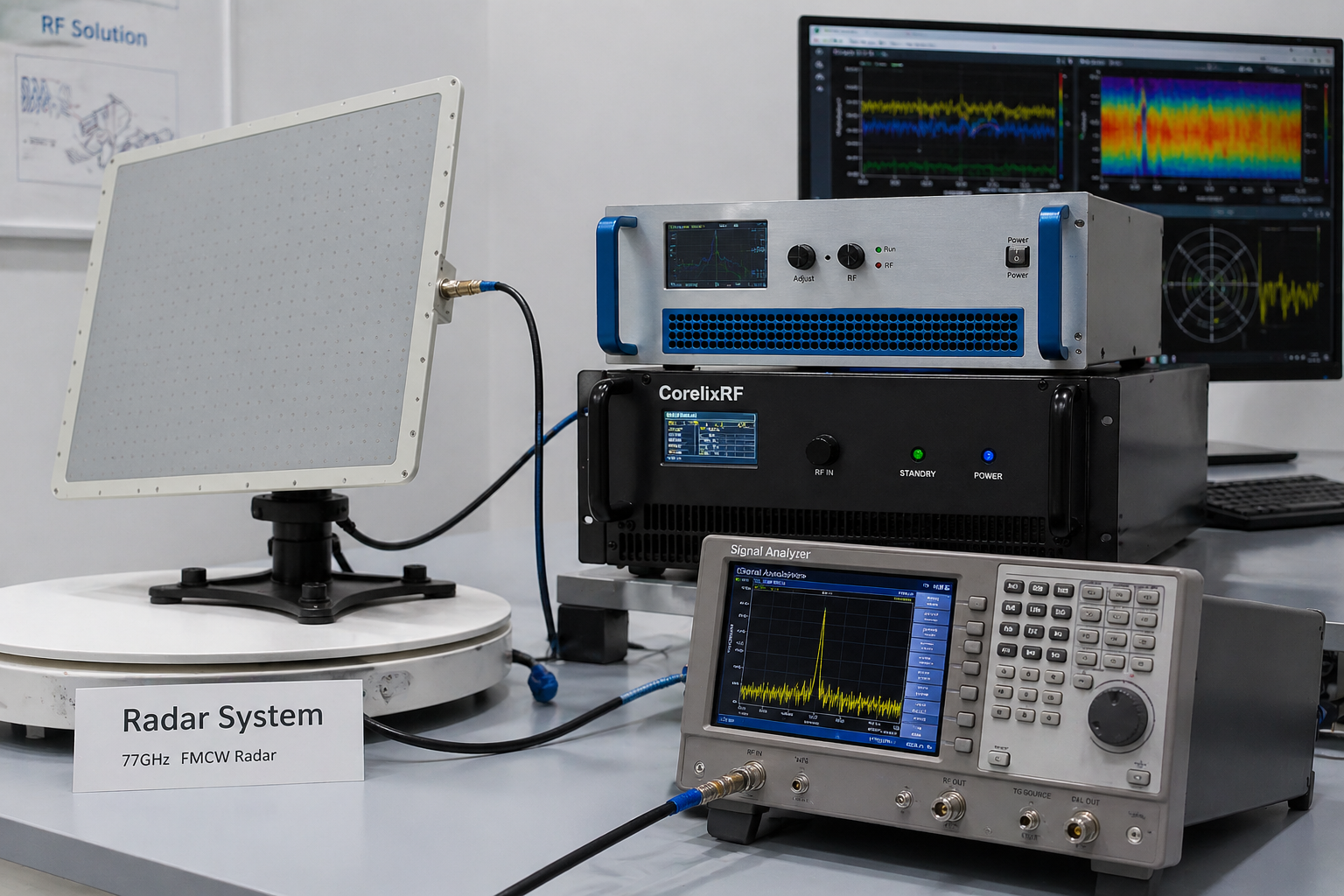 Radar / mmWave Sensing
01 // APPLICATION
Radar & RF Sensing Systems
Role in system:
Increase transmit RF power to extend detection range and improve echo signal strength in high-frequency radar and mmWave sensing systems.
Best fit: Radar front-end validation, RF sensing platforms, high-frequency transmitter chains.
 Ka / mmWave Communication
02 // APPLICATION
Ka / mmWave Communication Systems
Role in system:
Improve link budget by boosting transmit power and compensating for high-frequency path loss in broadband communication links.
Best fit: mmWave communication testing, high-frequency wireless links, RF communication validation.
 Test & Measurement
03 // APPLICATION
RF Test & Measurement Systems
Role in system:
Provide stable, repeatable RF output for device validation, signal chain testing, automated measurement platforms, and lab-based RF performance verification.
Best fit: R&D labs, production test benches, RF validation systems.
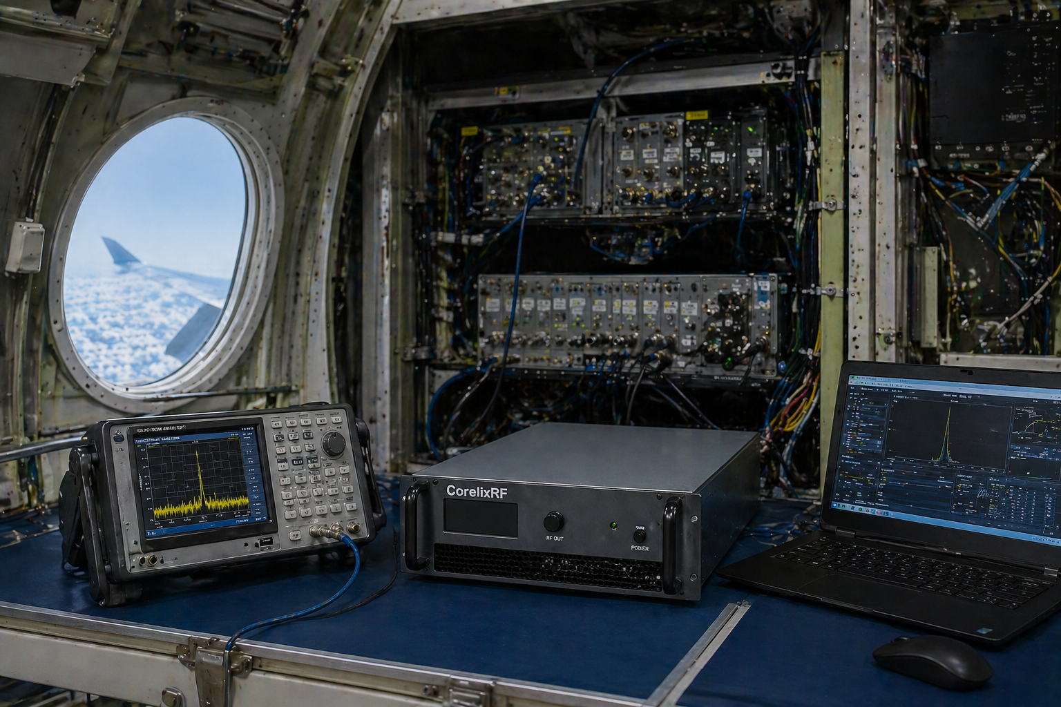 Aerospace & Avionics RF
04 // APPLICATION
Aerospace & Avionics RF Validation
Role in system:
Support controlled high-frequency RF environments for avionics subsystems, airborne RF payload testing, and system-level validation in aerospace development programs.
Best fit: Avionics testing, aerospace RF equipment validation, airborne communication simulation.
 RF System Integration
05 // APPLICATION
RF System Integration
Role in system:
Adapt amplifier configuration to match SDR, antenna, rack-mounted RF chain, cooling, control, and mechanical integration requirements for complete RF front-end platforms.
Best fit: SDR + amplifier + antenna systems, RF front-end platforms, rack-mounted RF systems.
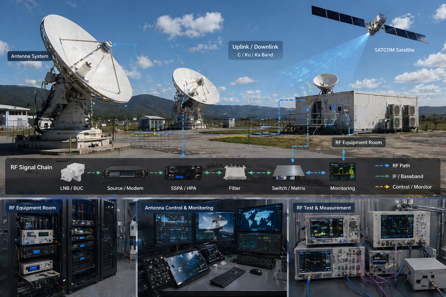 SATCOM / Ka-Band
06 // APPLICATION
SATCOM / Ka-Band Ground Terminals
Role in system:
Support uplink amplification, ground terminal RF chains, and satellite payload simulation with waveguide output configurations required for SATCOM integration.
Best fit: Ka-band ground station testing, SATCOM terminal validation, payload simulation.
Procurement Guidance
Before Ordering an 18–40 GHz RF Power Amplifier
| Buyer Concern | What to Verify | CorelixRF Answer |
|---|---|---|
| Rated Output Power | Ask for full-band power data — not just spot-frequency specs | UNIT-LEVEL RF TEST DATA |
| Gain Varies Across Band | Check gain flatness data — confirmed and documented in datasheets | GAIN FLATNESS REVIEWED |
| Wrong Output Interface | Confirm connector and waveguide type: 2.92 mm, WRD180, WR42 | 2.92 mm / WAVEGUIDE OPTIONS |
| Thermal Risk | Check chassis cooling design — verified under full output load | AIR / FORCED-AIR COOLING |
| System Mismatch | Request RF chain review — signal source, amp, antenna, integration | ENGINEERING REVIEW AVAIL. |
| No Project Customization | Ask about feasibility for custom frequency, power, interface, enclosure | SEMI-CUSTOM ENG. SUPPORT |
| Supplier Is Manufacturer | Source factory with in-house engineering — not a reseller | SOURCE FACTORY |
| Test Data Before Purchase | Unit-level test records available for power, gain, VSWR, harmonics | DATA ON REQUEST |
Why CorelixRF
Factory Capability & Documentation Support
CorelixRF is a source factory for RF power amplifiers, SDR signal source modules, antennas, and RF front-end integration platforms. We support standard products, OEM / ODM development, and project-based customization for customers who need stable RF performance and engineering communication.
330
Total Employees
168
R&D Engineers
1,400+
Test Instruments
8 Labs
RF Laboratories
CorelixRF Manufacturing Facility — 33,995 m²
RF Test Laboratory — 1,400+ Instruments
8 RF Laboratories · mmWave Capable
Continue Your RF Amplifier Review
Related CorelixRF Engineering Paths
Use these internal paths when your project needs a different frequency band, a custom amplifier configuration, system-level integration, or more factory capability review before RFQ.
6–18 GHz Broadband RF Amplifiers
Compare with the 6–18 GHz CRF-PA-6000M18000M series when your project does not require full 18–40 GHz mmWave coverage.
View 6–18 GHz Series → Category OverviewHigh Frequency RF Power Amplifiers
Return to the high-frequency amplifier overview when your requirement is still between S/C-band, 6–18 GHz, 18–40 GHz, or a focused mmWave band.
Open High-Frequency Overview → Custom EngineeringCustom RF Amplifier Options
Use this path for non-standard frequency windows, special connector layouts, monitoring functions, rack structures, cooling paths, or control interfaces.
Explore Custom Options → System IntegrationRF Systems & Front-End Integration
Continue here if the amplifier must be reviewed as part of a wider RF chain, subsystem cabinet, SDR chain, antenna path, or OEM front-end platform.
View RF Systems → Factory CapabilityRF Manufacturing & Test Capabilities
Review CorelixRF factory resources, RF test equipment, engineering validation, quality system, documentation support, and production capability.
View Capabilities → Company ReviewAbout CorelixRF
Use this path when your procurement team needs company background, factory positioning, qualification context, and manufacturer-level credibility.
Learn About CorelixRF →Datasheet, measured data and custom review requests on this page still use the RFQ / data request popup. These links are for deeper technical review and internal navigation.
Frequently Asked Questions
18–40 GHz RF Power Amplifier FAQ
Start Your RF Project
Request 18–40 GHz Data Review
Send your frequency range, output power target, RF connector or waveguide requirement, control interface, rack format, cooling preference and application details. CorelixRF will review whether a standard 18–40 GHz model class or a custom mmWave configuration is more suitable.
To speed up review, include:
- Required frequency range
- Target output power
- Input signal level
- RF input / output connector
- Control interface preference
- Cooling or enclosure requirement
- Application or RF chain description
- Quantity and project stage
Request Datasheet & Custom Options
Submit your 18–40 GHz RF amplifier requirement and our engineering team will review and respond within 24–48 hours.
18-40 GHz microwave RFQ evidence
Request 18-40 GHz data with the quotation
For 18-40 GHz amplifier projects, CorelixRF should review interface type, gain flatness, output power target, thermal design, waveguide or coaxial transition, control requirements and factory test records before final configuration.
Confirm sub-band coverage, connector or waveguide interface, drive level, output power target and integration limits.
Define duty cycle, cooling method, load condition, mismatch tolerance and protection expectations.
Ask for measured output, gain flatness, harmonics/spurious, burn-in or FAT checklist and delivery documentation.