6–18 GHz Broadband RF Power Amplifiers
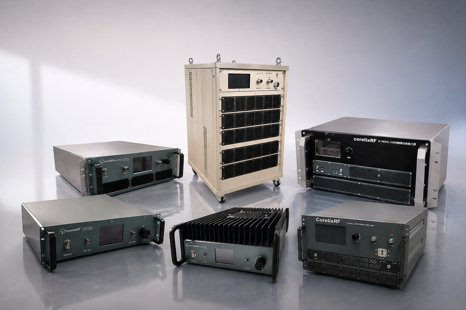
Factory-built 6–18 GHz GaN RF amplifier series covering datasheet-supported power classes from 10W to 1000W, with SMA, N-type or WRD650 output options, RS485 / LAN control, air-cooled rack or compact chassis formats, and project-based customization support.
6–18 GHz Full Coverage
Power Classes
High Efficiency RF Design
System Integration Ready
Before Every Shipment
Before You Select a 6–18 GHz RF Power Amplifier
Output power is only one part of the decision. Connector type, gain flatness, cooling, control interface and measured data all affect whether the amplifier can be integrated into a real RF system.
Platform Coverage and Custom Engineering Support
CorelixRF provides the CRF-PA-6000M18000M series as a datasheet-supported 6–18 GHz amplifier family, covering compact low-power units, rack-mount mid-power systems and project-configured high-power platforms. Custom review is available when connector, chassis, monitoring, power supply or control requirements differ from the standard datasheet.
Key Specifications for the CRF-PA-6000M18000M Series
Use this summary to quickly confirm whether the 6–18 GHz series matches your frequency band, output power class, connector, control and integration requirements before reviewing the full model table.
6–18 GHz RF Amplifier Model Range
Swipe or scroll horizontally to compare frequency, power, gain, connector, control and package options.
| Model Number | Frequency | Output Power | Gain | Gain Flatness | Tech | Connector (In/Out) | Control | Recommended Use | Package | Data Request |
|---|---|---|---|---|---|---|---|---|---|---|
| CRF-PA-6000M18000M-10W | 6–18 GHz | 10W | 40 dB | ±4 dB | GaN | SMA-F / SMA-F | RS485 | Compact RF testing / small-signal amplification | Mini Chassis | Request Data |
| CRF-PA-6000M18000M-16W | 6–18 GHz | 16W | 42 dB | ±4 dB | GaN | SMA-F / SMA-F | RS485 | Compact RF testing / small-signal amplification | Mini Chassis | Request Data |
| CRF-PA-6000M18000M-25W | 6–18 GHz | 25W | 45 dB | ±4 dB | GaN | N-F / N-F | RS485 / LAN | Lab validation / communication testing | 19", 3U | Request Data |
| CRF-PA-6000M18000M-30W | 6–18 GHz | 30W | 45 dB | ±4 dB | GaN | N-F / N-F | RS485 / LAN | Lab validation / communication testing | 19", 3U | Request Data |
| CRF-PA-6000M18000M-40W | 6–18 GHz | 40W | 46 dB | ±4 dB | GaN | N-F / N-F | RS485 / LAN | Lab validation / communication testing | 19", 3U | Request Data |
| CRF-PA-6000M18000M-50W Popular | 6–18 GHz | 50W | 50 dB | ±4 dB | GaN | SMA-F / N-F | RS485 | Lab validation / communication testing | 330×200×60 mm | Request Data |
| CRF-PA-6000M18000M-80W | 6–18 GHz | 80W | 50 dB | ±5 dB | GaN | N-F / N-F | RS485 / LAN | Lab validation / communication testing | 19", 3U | Request Data |
| CRF-PA-6000M18000M-120W | 6–18 GHz | 120W | 50 dB | ±5 dB | GaN | N-F / N-F | RS485 / LAN | High-power test / interference platforms | 19", 4U | Request Data |
| CRF-PA-6000M18000M-160W | 6–18 GHz | 160W | 50 dB | ±5 dB | GaN | N-F / N-F | RS485 / LAN | High-power test / interference platforms | 19", 4U | Request Data |
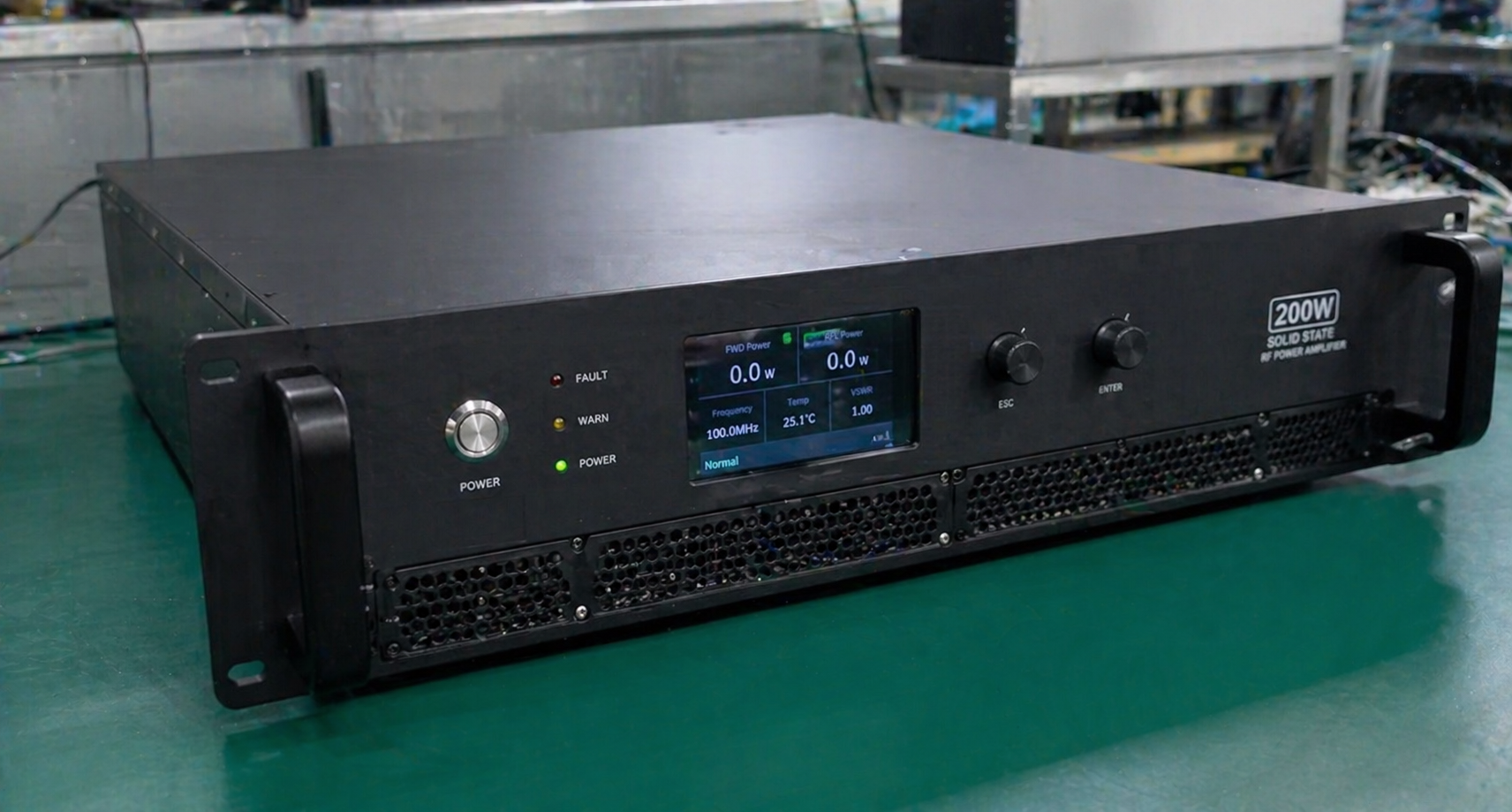
| CRF-PA-6000M18000M-200W High Power | 6–18 GHz | 200W | 53 dB | ±5 dB | GaN | N-F / WRD650 | RS485 / LAN | High-power test / interference platforms | 19", 6U | Request Data |
| CRF-PA-6000M18000M-250W | 6–18 GHz | 250W | 54 dB | ±5 dB | GaN | N-F / WRD650 | RS485 / LAN | High-power test / interference platforms | 19", 6U | Request Data |
| CRF-PA-6000M18000M-300W | 6–18 GHz | 300W | 54 dB | ±6 dB | GaN | N-F / WRD650 | RS485 / LAN | High-power test / interference platforms | 19", 6U | Request Data |
| CRF-PA-6000M18000M-400W Engineering Review | 6–18 GHz | 400W | 56 dB | ±6 dB | GaN | N-F / WRD650 | RS485 / LAN | Project-driven high-power RF systems | TBD / Custom | Request Data |
| CRF-PA-6000M18000M-500W High Power Engineering Review | 6–18 GHz | 500W | 57 dB | ±6 dB | GaN | N-F / WRD650 | RS485 / LAN | Project-driven high-power RF systems | TBD / Custom | Request Data |
| CRF-PA-6000M18000M-1000W Engineering Review | 6–18 GHz | 1000W | 60 dB | ±6 dB | GaN | N-F / WRD650 | RS485 / LAN | Project-driven high-power RF systems | TBD / Custom | Request Data |
Select by Power Level and System Requirement
Choose the amplifier tier that matches your system's RF output requirement, cooling environment, and integration complexity.
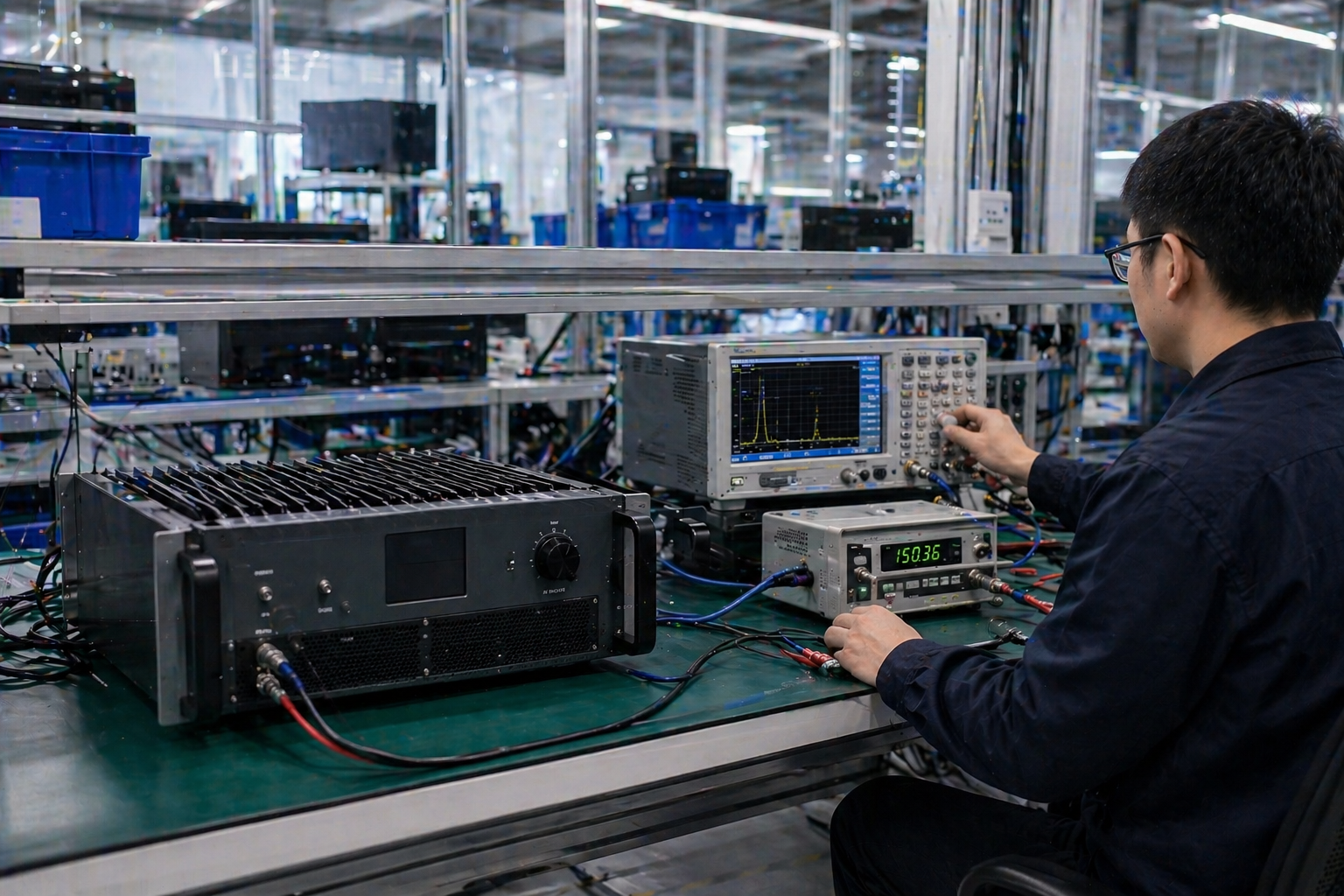
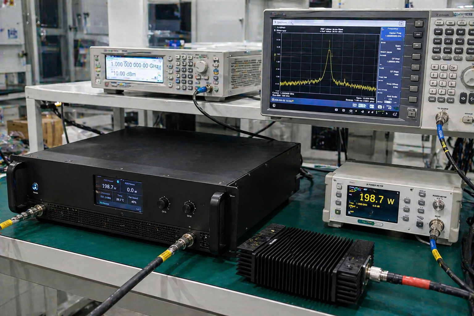
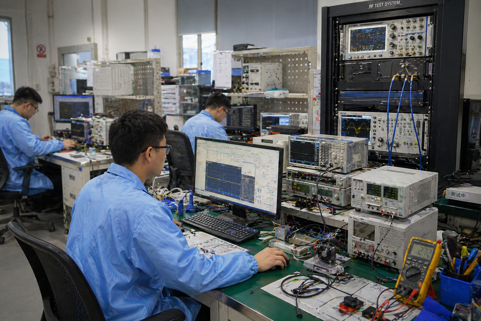
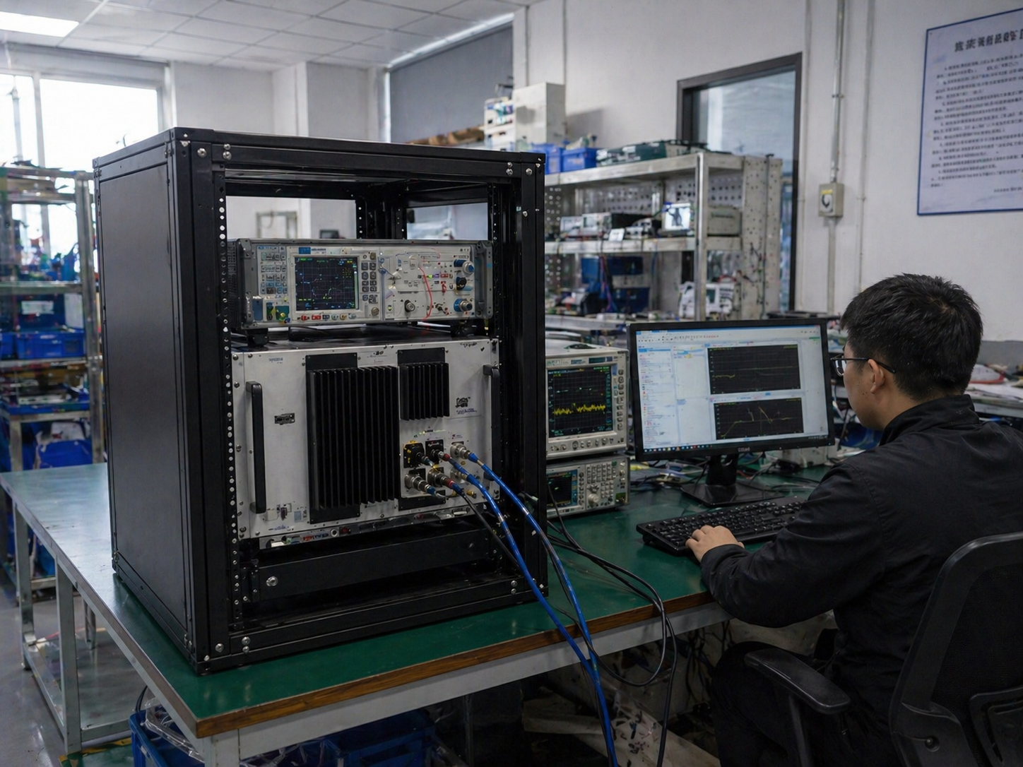
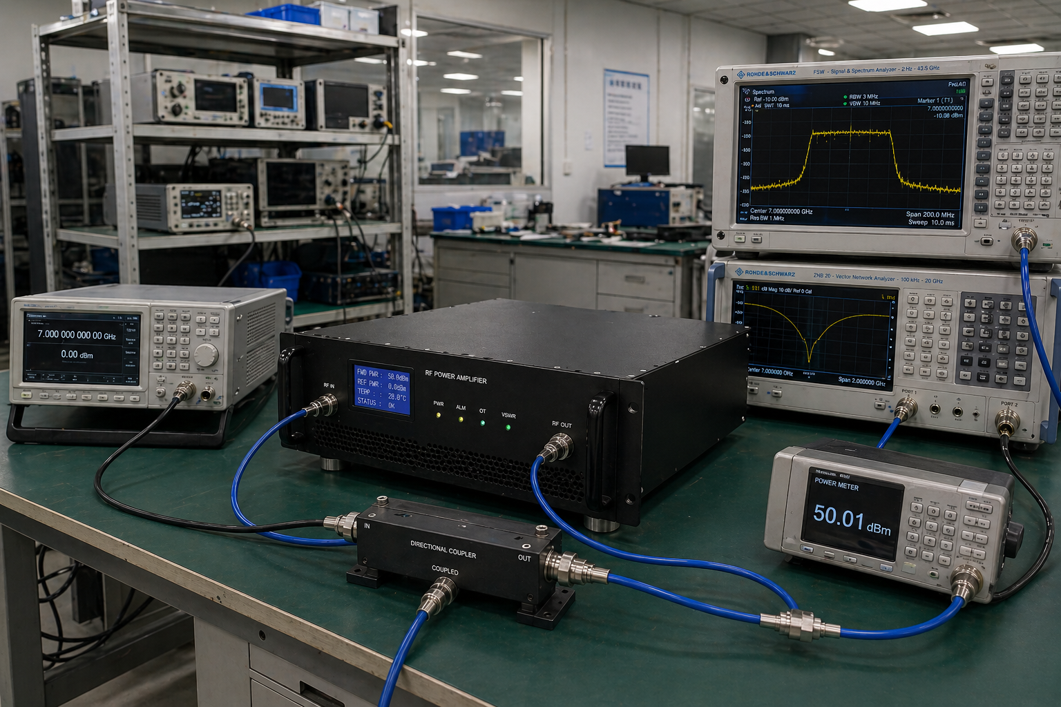
Factory Testing Evidence for 6–18 GHz RF Amplifier Review
Instead of separating test photos, test steps and datasheet documents into disconnected blocks, this section shows one review path: what is checked, what evidence can be supplied, and what high-power configurations must confirm before quotation.
Review rated output behavior across the 6–18 GHz operating band where measured curves are available.
Confirm gain flatness class, input match and system-level integration risk before model selection.
Review SMA, N-type or WRD650 interface requirements, chassis format and installation references.
High-power models require review of airflow, load condition, AC supply, chassis space and output interface.
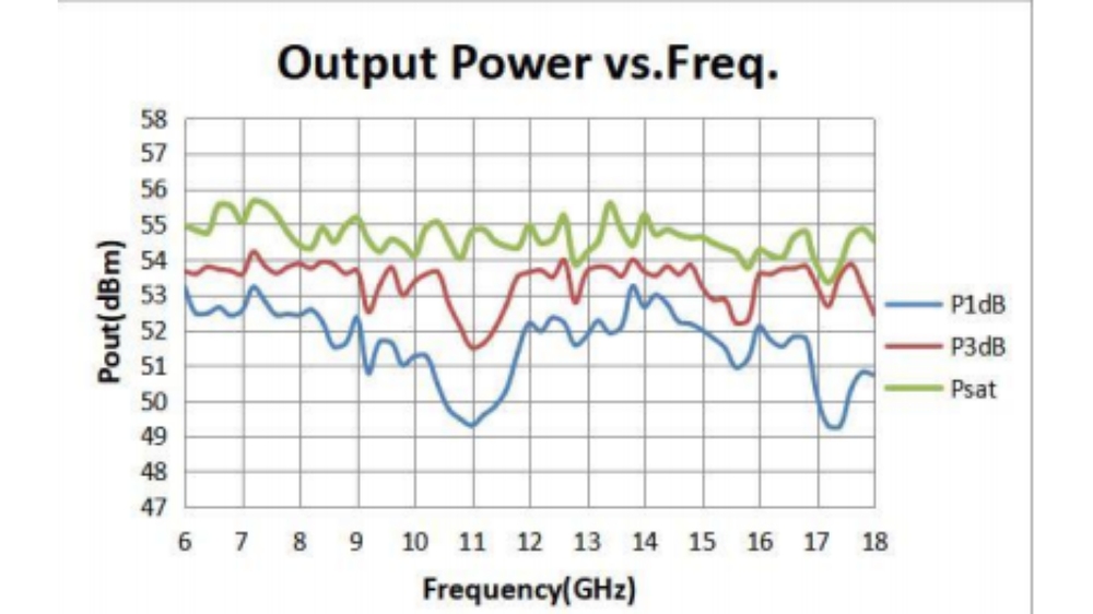 Output Power Curve
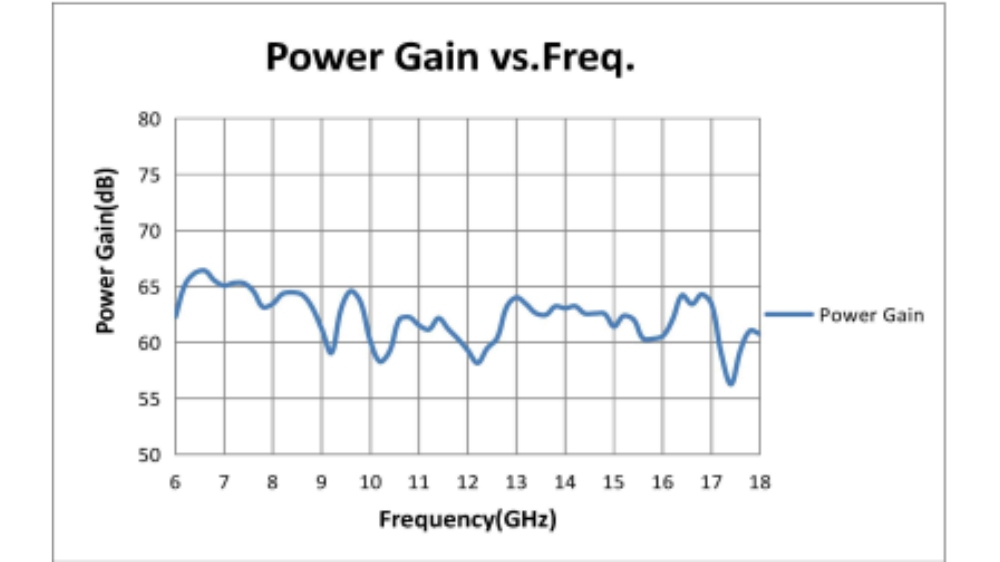 Gain / VSWR Reference
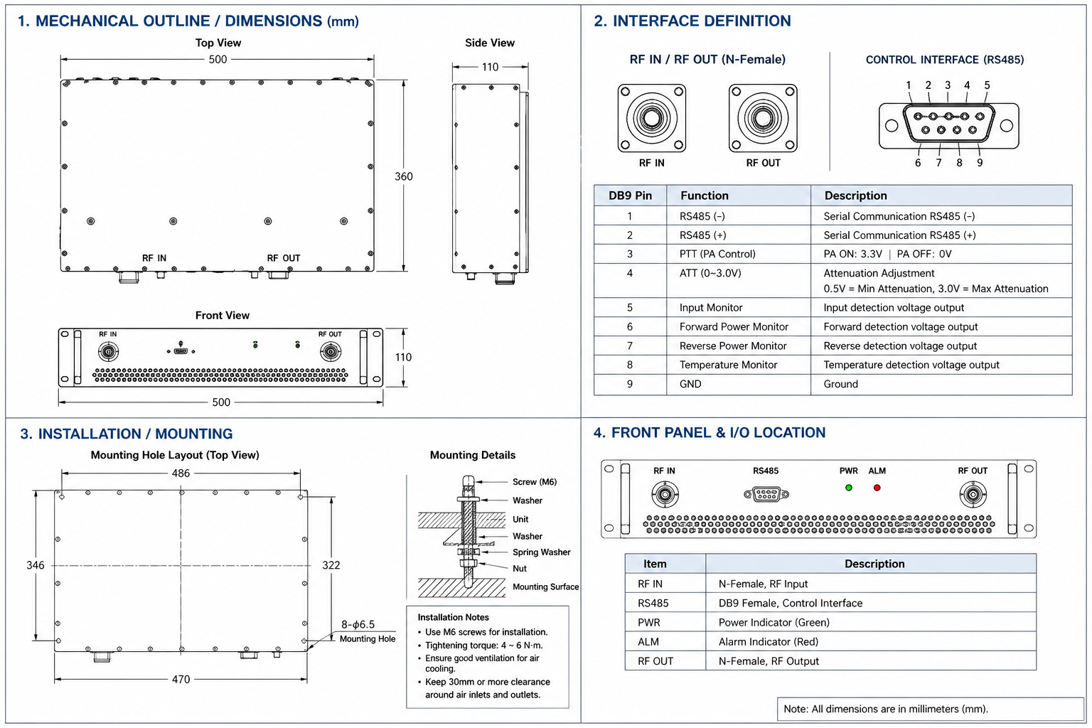 Mechanical Outline
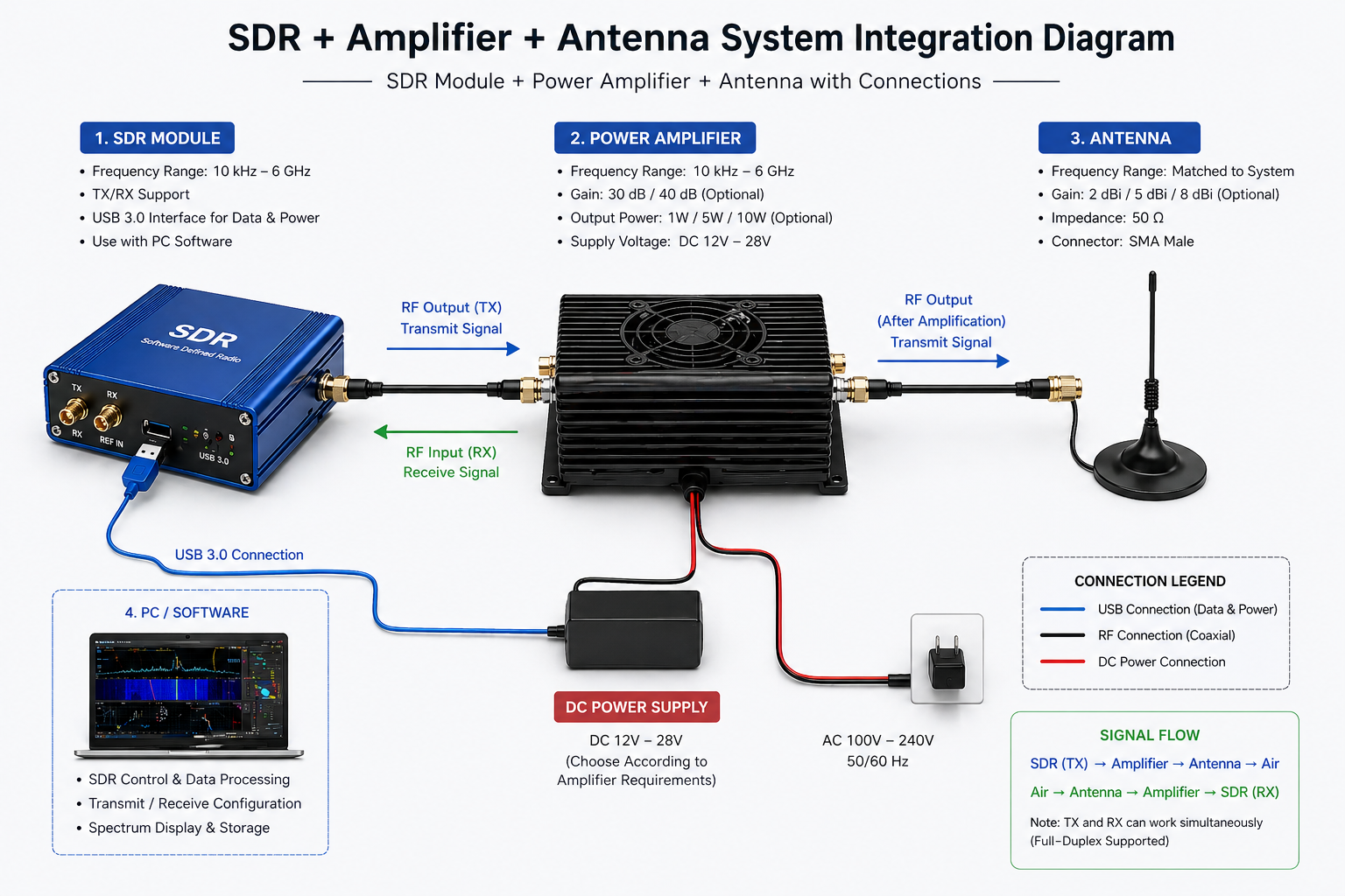
Configuration and Integration Options
This section does not repeat the core RF specifications. It defines what can be reviewed or customized when the amplifier enters a real rack, test bench or OEM RF front-end system.
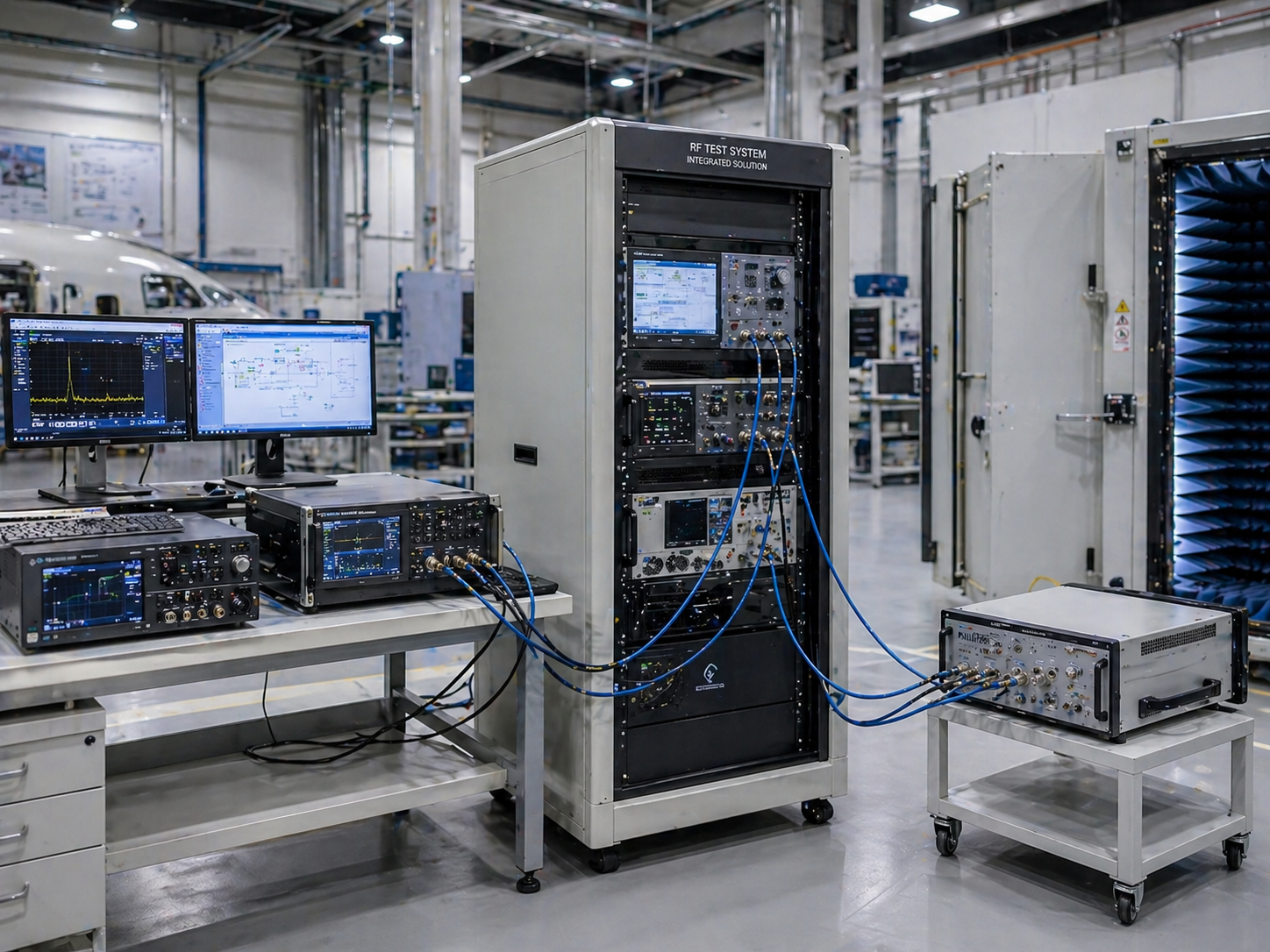
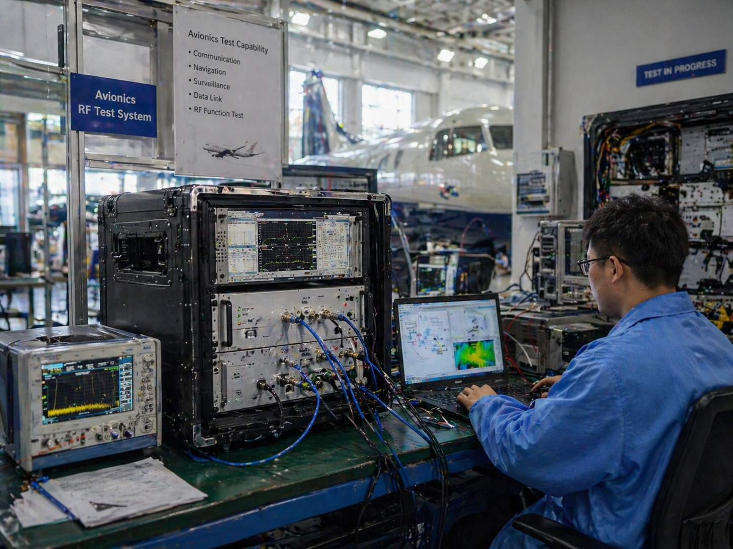
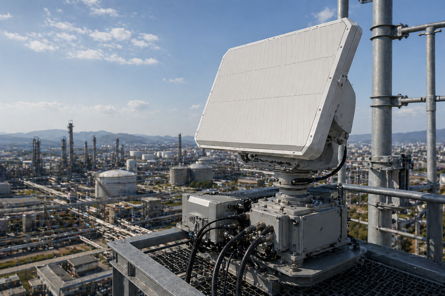
Trusted in RF System Applications
CorelixRF 6–18 GHz amplifier platforms are used in project-driven RF systems where broadband power, control interface, thermal stability, and integration support matter.
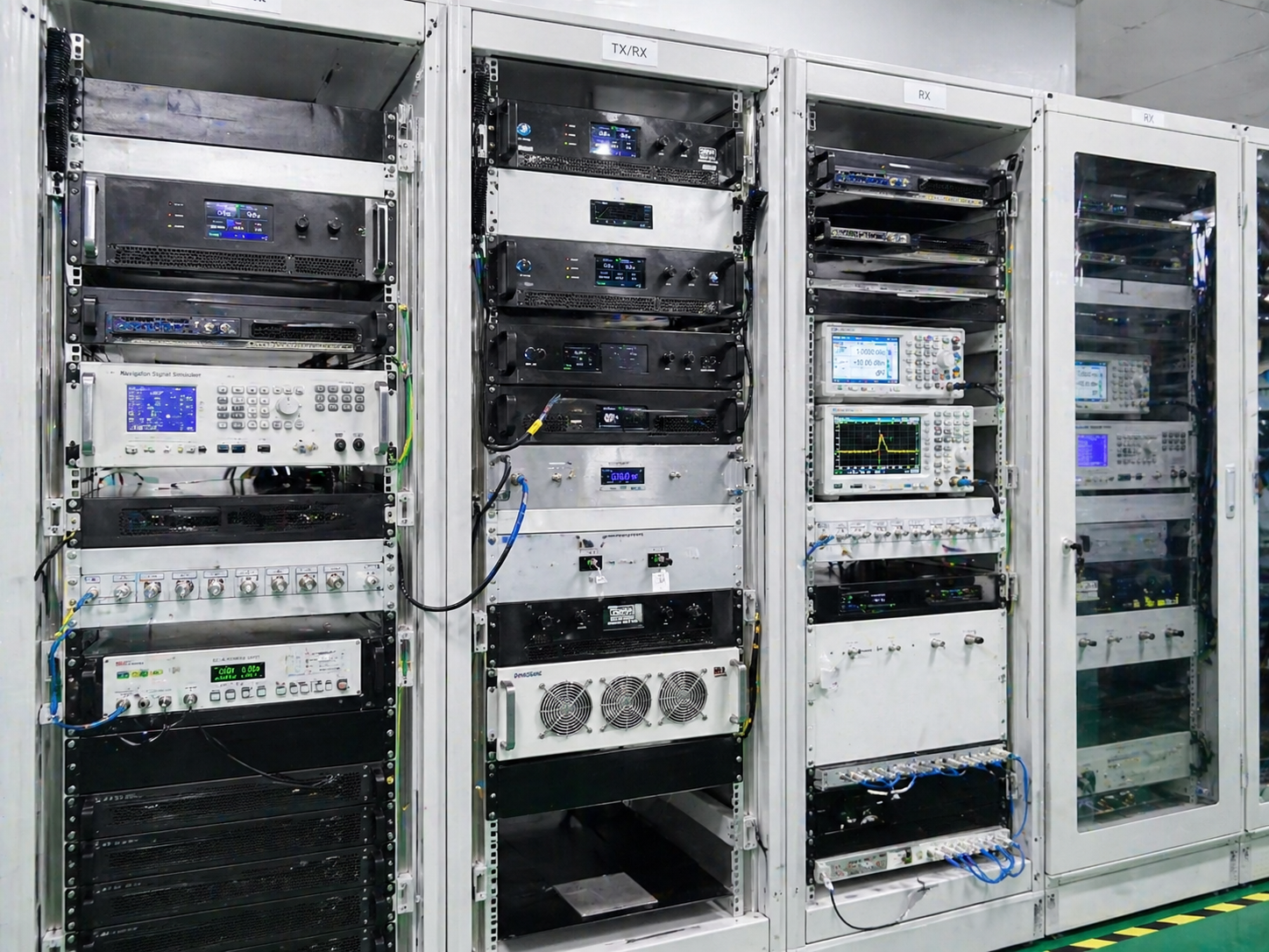
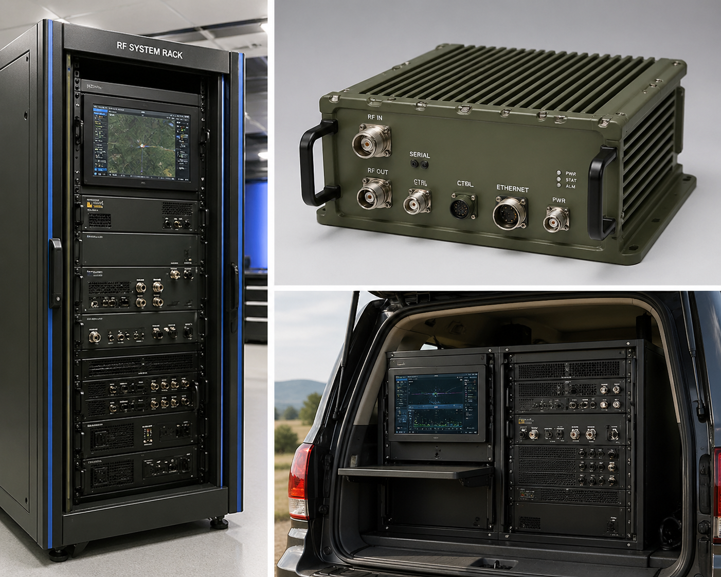
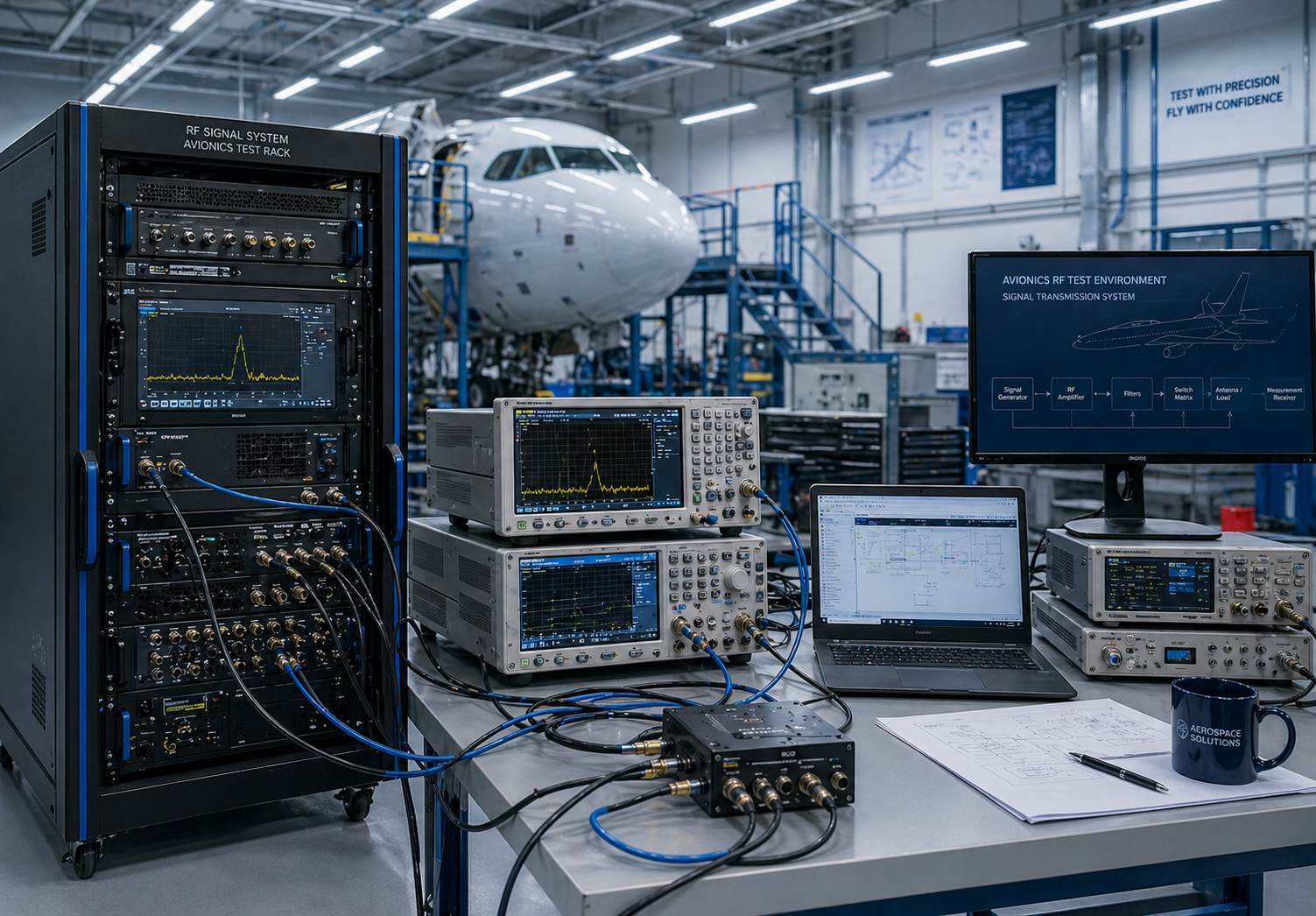
Applications for 6–18 GHz RF Power Amplifiers
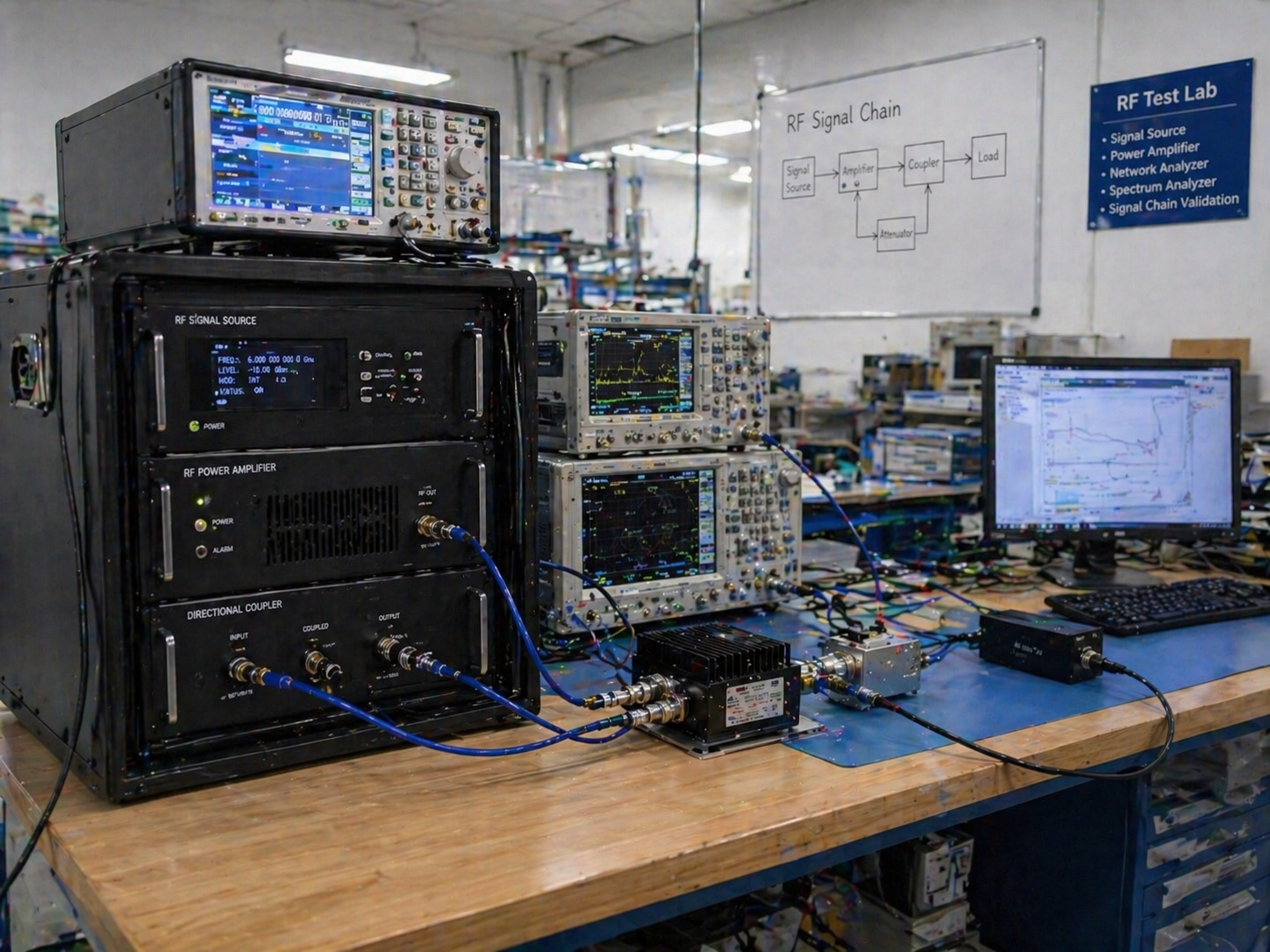
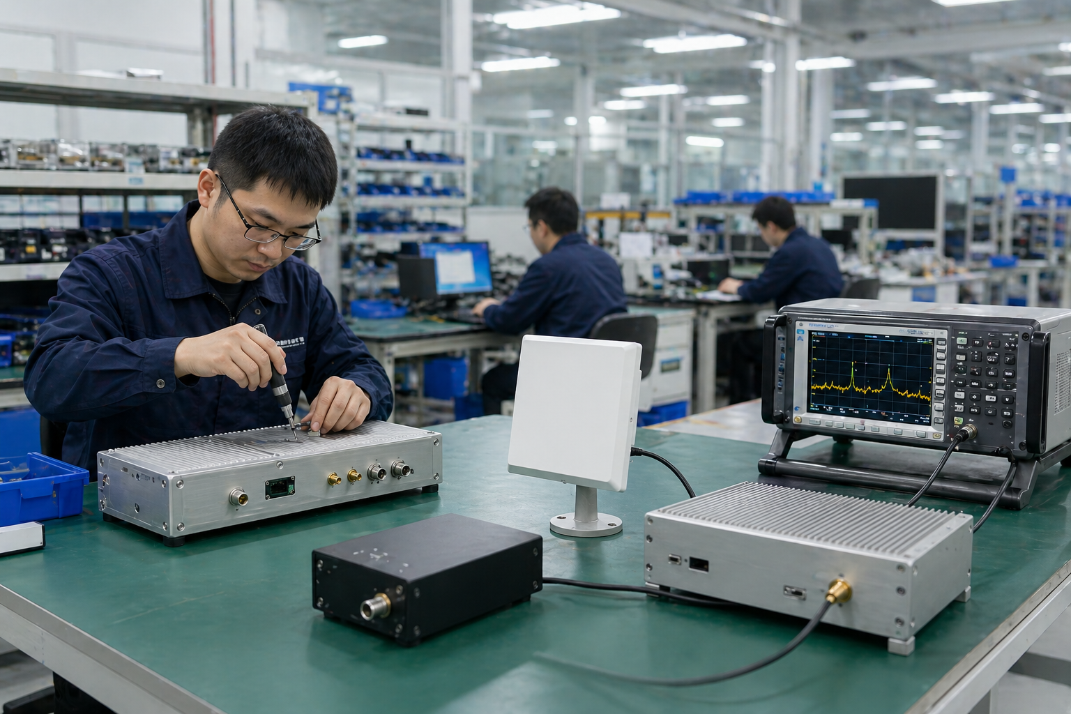
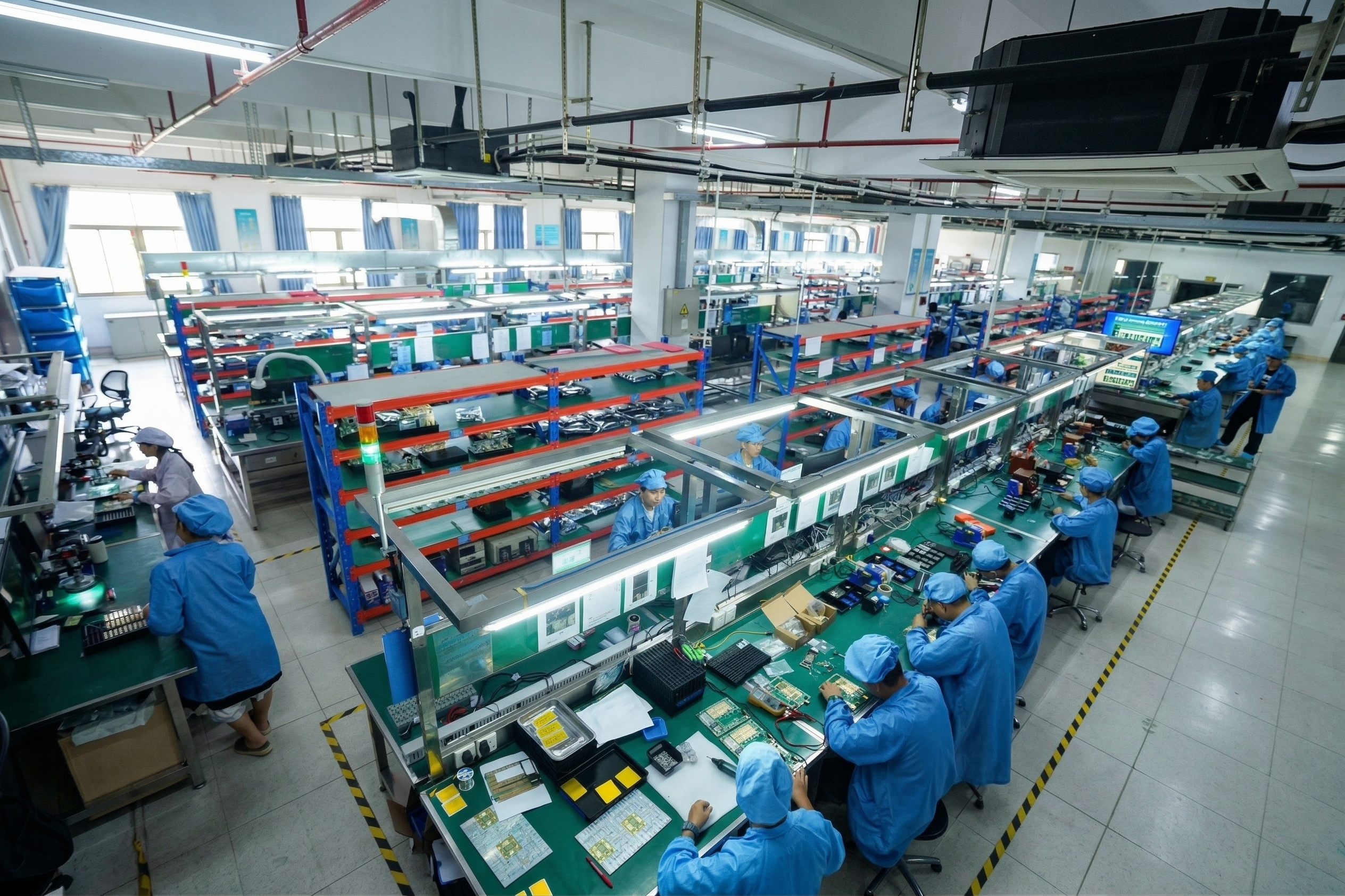
Built by CorelixRF, an RF Amplifier Source Factory
CorelixRF supports RF amplifier projects from design, prototyping, RF testing, mechanical integration, production, and final shipment. For 6–18 GHz amplifier platforms, our engineering and production teams can support standard model selection, project customization, and system-level integration review.
Quality Framework for RF Amplifier Production
What to Confirm Before Buying a 6–18 GHz RF Amplifier
Use this checklist to evaluate any 6–18 GHz amplifier supplier — whether evaluating CorelixRF or any alternative platform.
Frequently Asked Questions
Need a 6–18 GHz Amplifier for Your RF System?
Send your frequency range, required output power, control interface preference, cooling requirement, and application context. CorelixRF will recommend a suitable 6–18 GHz amplifier configuration and provide a project datasheet and quotation within 24–48 hours.