Signal Source
SDR Source Path
For compact SDR source modules, waveform control and SDR-driven RF chains that need a verified amplifier path.
View SDR Platform →Factory-Direct RF Front-End Platform Manufacturer
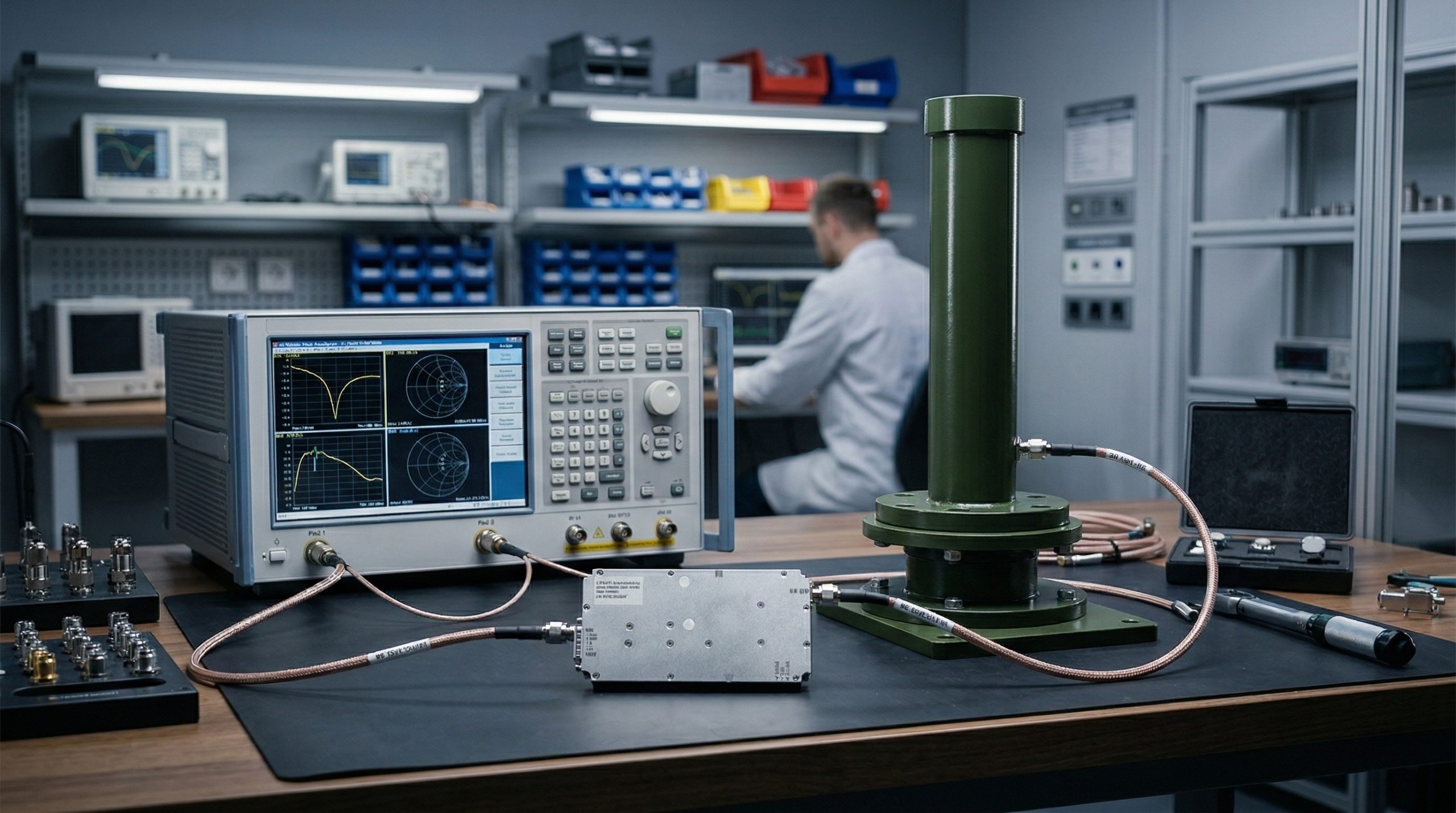
SDR + RF Amplifier + Antenna / Load / DUT Integration
Start from CorelixRF SDR, amplifier and antenna platforms, then adjust frequency, output power, waveform, connector, interface and deployment format around your project. This page helps engineering teams move from loose component selection to a reviewed RF front-end path.
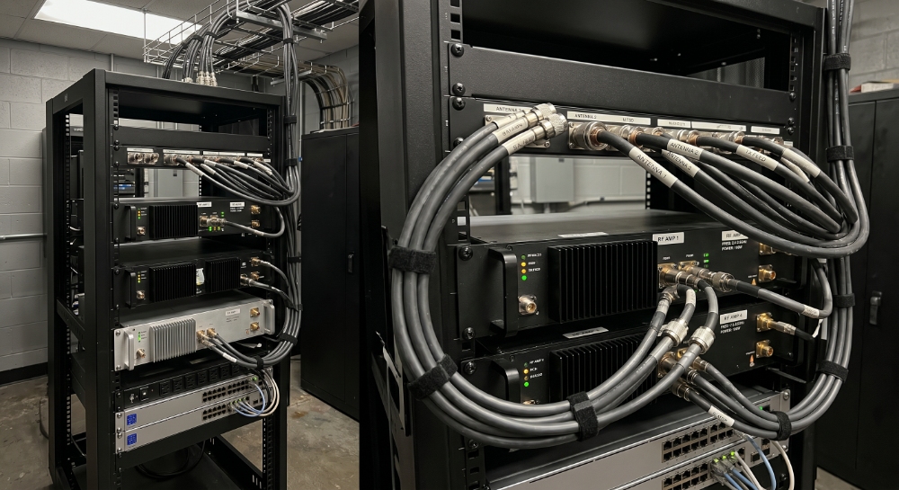
RF Front-End Platform Structure
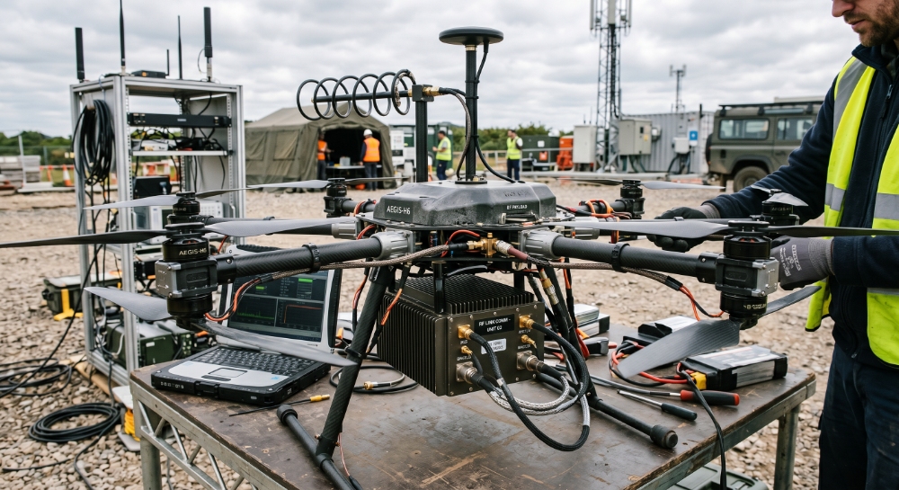
SDR / RF Source
Signal generation · waveform control
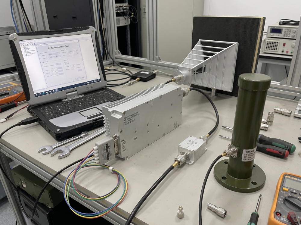
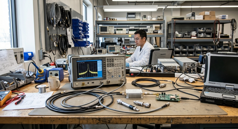
RF Power Amplifier
CW · pulsed · EMC · wideband paths
Antenna / Load / DUT
Omni · directional · OEM RF port
6 GHz
SDR Source Range
Platform
Not Loose Parts
OEM/ODM
Adjustment Support
SDR + PA + ANT
Platform Matching
100 MHz – 6 GHz
Frequency Coverage
Semi-Standard
Customizable Architecture
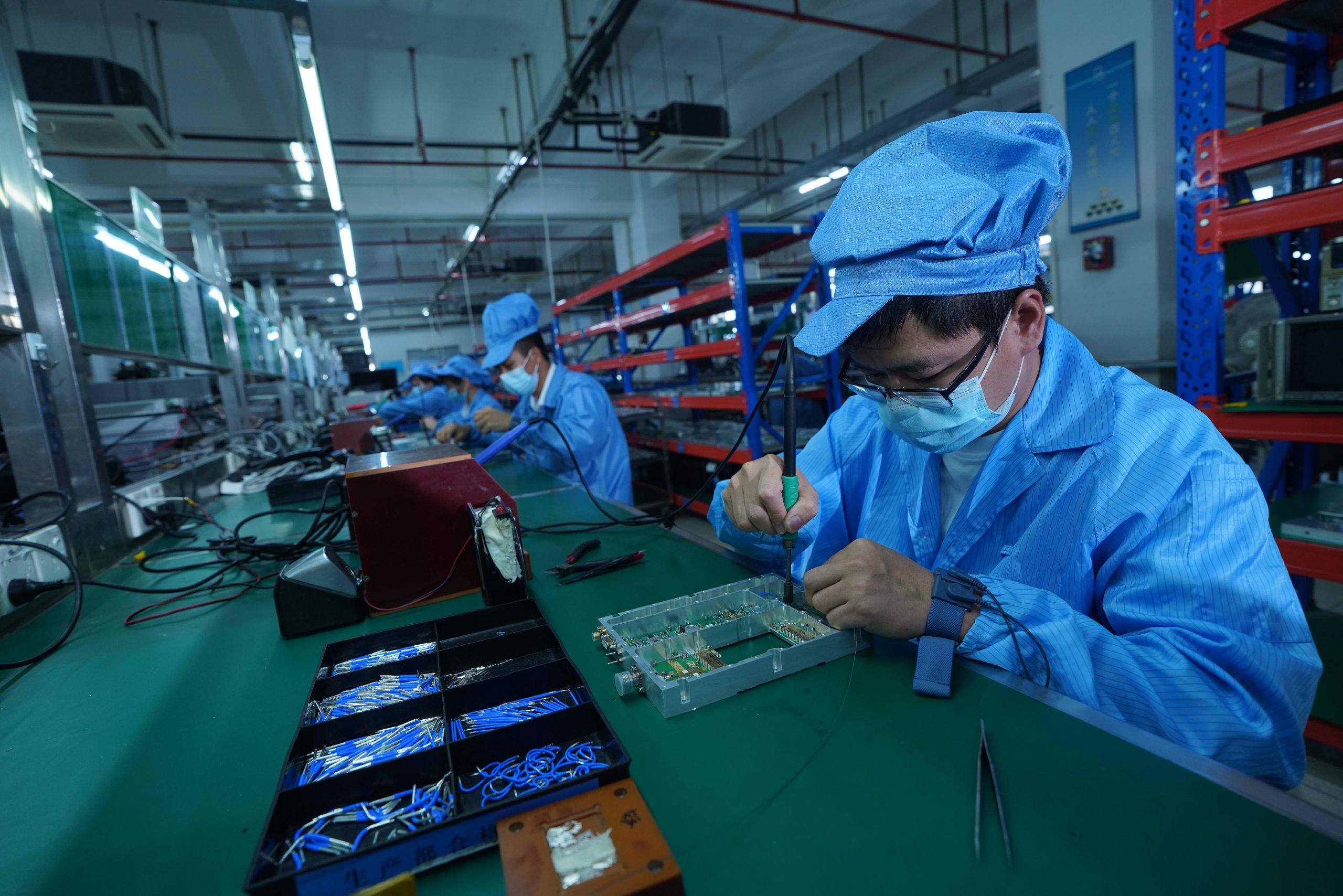
In-House
Testing & Validation
OEM / ODM
Project Support
48h
Engineering Review
Choose Your RF Front-End Path
Start with the closest path, compare the related CorelixRF platform page, then request a factory review when frequency, power, antenna or integration details need confirmation.
Signal Source
For compact SDR source modules, waveform control and SDR-driven RF chains that need a verified amplifier path.
View SDR Platform →Power Stage
For CW, pulsed, EMC, UHF and wideband amplifier platform selection by frequency range and output power class.
Explore Amplifiers →Baseline Platform
Start from existing CorelixRF platform models before project adjustment for frequency, connector, control or enclosure details.
View Standard Platforms →Project Adjustment
Adjust frequency, output power, enclosure, power supply, thermal path or control interface details around the real project.
View Custom Amplifiers →Output Path
Review omnidirectional, directional or custom antenna output conditions, including power handling, cable path and VSWR risk.
View Antenna Options →Engineering Review
For OEM integration, special waveform, connector, enclosure or system-level RF chain review before sourcing components.
Ask Matching Review →Who This Page Is For
Use this page when your RF project needs a matched signal source, power stage and output-side path instead of separate components from different suppliers. It is especially useful before committing to a frequency band, output power class, antenna type or OEM integration format.
SDR + Amplifier Matching
Match source level, input requirement and frequency overlap before selecting the amplifier path.
Amplifier + Antenna Review
Confirm power handling, VSWR, cable loss and output-side conditions before the RF chain is finalized.
Platform-Based Customization
Adjust frequency, output power, connector, control and mechanical layout around a proven platform baseline.
OEM RF Front-End Integration
Support enclosure-level integration, small-batch engineering review and project-specific delivery requirements.
Platform Definition
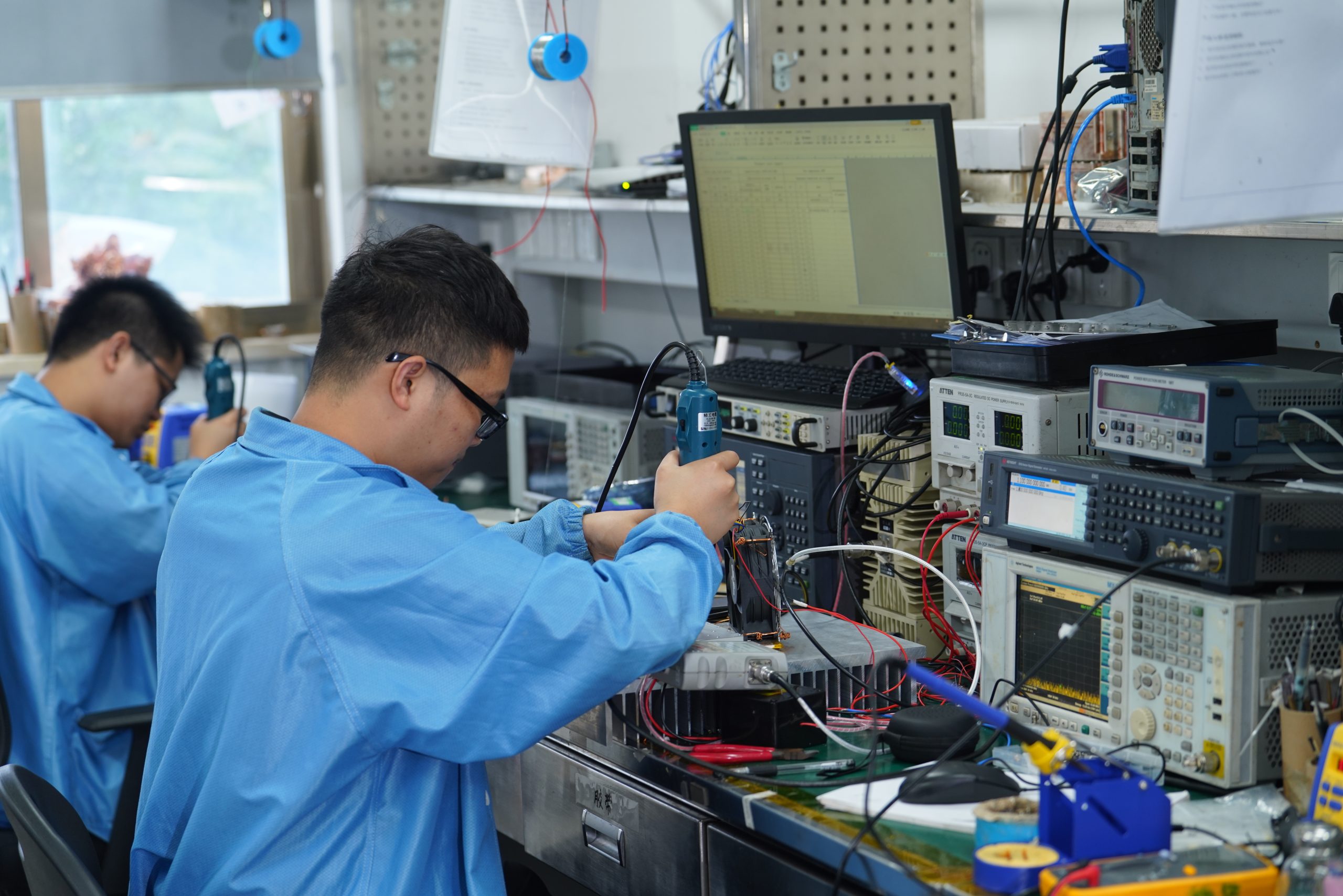
CorelixRF reviews the source, amplifier and output-side condition as one RF chain instead of treating them as separate components. The goal is to confirm whether the selected source level, gain path, output power, cable path and antenna/load condition can work together before procurement.
01
SDR / RF Source
Signal source, waveform path and control interface.
02
RF Power Amplifier
CW, pulsed, EMC or wideband power stage matched by frequency and power.
03
Output-Side Path
Antenna, load, DUT or OEM RF port with power and VSWR review.
04
Project Adjustment
Connector, control, cooling, layout and delivery format.
Typical RF Chain
SDR / RF Source
waveform · frequency · control
RF Power Amplifier
gain · output power · protection
Antenna / Load / DUT
VSWR · cable · output condition
Platform Strategy
Most projects do not need a full custom design from zero. CorelixRF starts from proven SDR, amplifier and antenna platform options, then adjusts the key RF, control and mechanical details around the project. This keeps the solution more practical than pure custom development while still allowing engineering-level changes.
Reference Combinations
Select the closest architecture, then continue to the related product path or request a matching review.
Source + Power
For SDR-driven RF source and CW amplifier matching where source level, input requirement and frequency overlap need confirmation.
View SDR Path →Source + Power + Output
For antenna-side output path review, including power handling, cable path, VSWR and system-level RF chain behavior.
View standard platform Path →Power + Output
For output power, VSWR, cable, attenuator, dummy load or DUT input condition review.
Explore Amplifiers →Project-Specific
For enclosure, control, connector, custom frequency range, power supply or project-specific mechanical requirements.
View Custom Path →Use Scenarios
Common project contexts where a matched RF front-end platform reduces integration risk without turning the page into a long application catalog.
Adjustment Scope
CorelixRF reviews the RF chain around your target band, power level, waveform, connector path, control interface and output-side condition. Standard platforms can be adjusted when the project requires a different frequency subset, connector layout, power supply, thermal path or OEM form factor.
Integration Risk Reduction
A platform review helps prevent mismatches before procurement, integration and field testing, especially when SDR, amplifier and antenna/load conditions are sourced as one chain.
Loose Component Risk
Frequency mismatch
Selected modules may not share the same usable operating range.
SDR output / amplifier input mismatch
The source level may be too low, too high or unstable for the amplifier input.
Antenna or load condition mismatch
VSWR, cable loss or load behavior can change the real output condition.
Multi-supplier responsibility gap
When parts come from different suppliers, integration responsibility becomes unclear.
CorelixRF Platform Review
Frequency overlap review
We confirm the shared operating range before recommending the path.
Source-to-amplifier matching
SDR/source level and amplifier input requirements are reviewed together.
Output-side condition review
Antenna, load, DUT, cable and VSWR conditions are considered before delivery.
One factory engineering contact
CorelixRF helps review the chain as one platform instead of isolated parts.
Factory Review
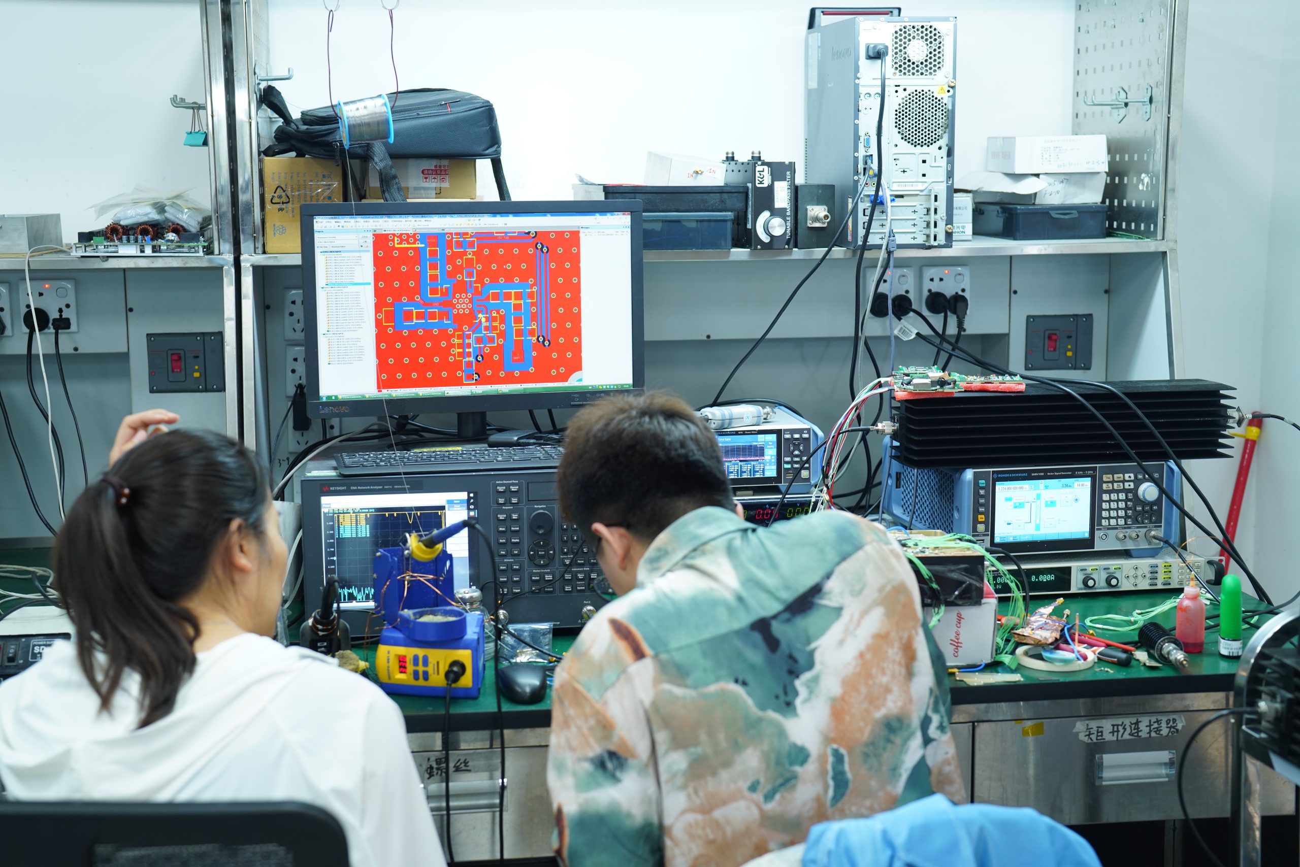
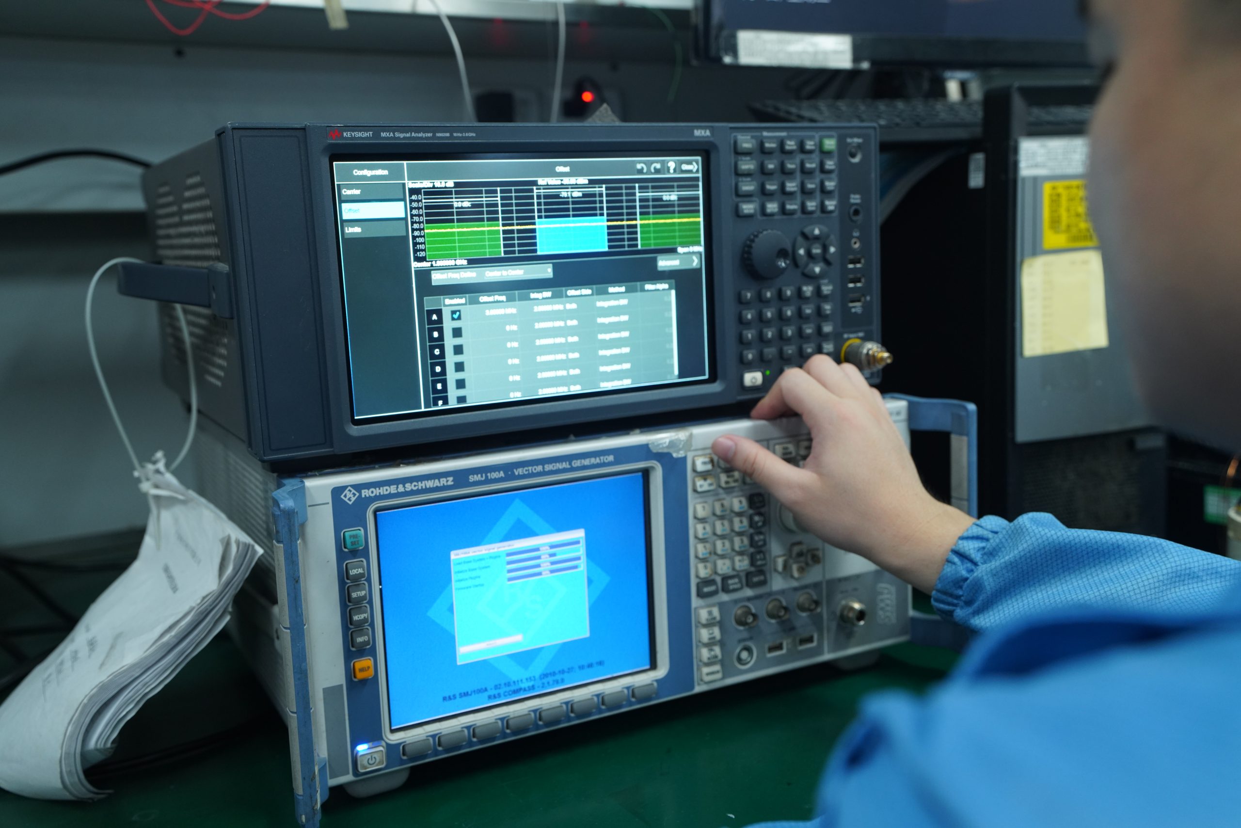
Before recommendation, CorelixRF checks the key RF chain conditions that affect real integration. This review connects the selected SDR/source path, amplifier class, antenna/load condition, connector path and delivery format.
01. Requirement Review
Frequency range, required output power, waveform/source type, antenna or load condition.
02. Platform Matching
SDR output level, amplifier input requirement, antenna/load power handling and interface compatibility review.
03. RF Chain Confirmation
Connector, cable, VSWR, control interface, cooling and mechanical details.
04. Delivery Support
Recommended platform path with test data, documentation support and factory delivery coordination.
Architecture
Use this structure as a starting point. Final selection depends on actual frequency, output power, source level, antenna/load condition, thermal path, connector layout and mechanical constraints.
SDR
Source / waveform path
PA
Power stage
ANT
Output path
OEM
Integration format
Reference Chain
01
Source
02
Amplifier
03
Output
Applications
Typical contexts where platform-based matching is more efficient than loose component sourcing, especially when output-side conditions must be confirmed before integration.
01
Source, power and antenna paths for RF system integration where the output condition must be reviewed together.
02
Matched amplifier and antenna paths for RF links that require frequency, gain and interface confirmation.
03
RF source module plus amplifier platform review for SDR-driven test or transmission chains.
04
Validation chains for DUT, load, attenuator or chamber input conditions.
05
Custom enclosure, control interface and delivery format for OEM RF subsystems.
06
Directional, omnidirectional or custom antenna paths matched with amplifier output conditions.
Process
A practical path from RF requirement to platform recommendation, without forcing every project into a full custom design cycle.
Frequency, power, waveform, output condition, connector preference and project stage.
Review SDR/source level, amplifier class, antenna/load condition and interface fit.
Check connector, cable, VSWR, control and layout.
Standard platform, custom adjustment or OEM review.
Why CorelixRF
CorelixRF combines SDR, amplifier and antenna platform resources with in-house RF engineering review for project-specific matching. This helps buyers reduce sourcing uncertainty while keeping a practical path for OEM/ODM adjustments.
Factory-direct RF manufacturer
SDR, amplifier and antenna platform support
In-house RF testing and validation
OEM / ODM customization
Unit-level RF data available

FAQ
CorelixRF Killing Page Paths
Choose the exact SDR, amplifier, antenna or custom platform path after the system-level review. These links help customers move from a broad RF front-end requirement to a focused Killing Page.
Standard, custom, band-specific, EMC and pulsed amplifier paths.
Antenna output and model comparison.
Tell Us Your RF Requirement
Share your frequency range, output power, signal source, antenna or load condition, interface and deployment requirements. CorelixRF will review the closest platform path before recommendation and confirm whether a standard baseline or custom adjustment is more suitable.
Helpful details for review
Frequency range
Required output power
SDR / waveform requirement
Antenna / load / DUT condition
Connector / control interface
Quantity / project stage
Start with a Platform Review
Open the inquiry popup to send your RF requirement. CorelixRF will guide the closest SDR, amplifier, antenna or custom platform path.
The inquiry popup collects your RF front-end requirements for engineering review.
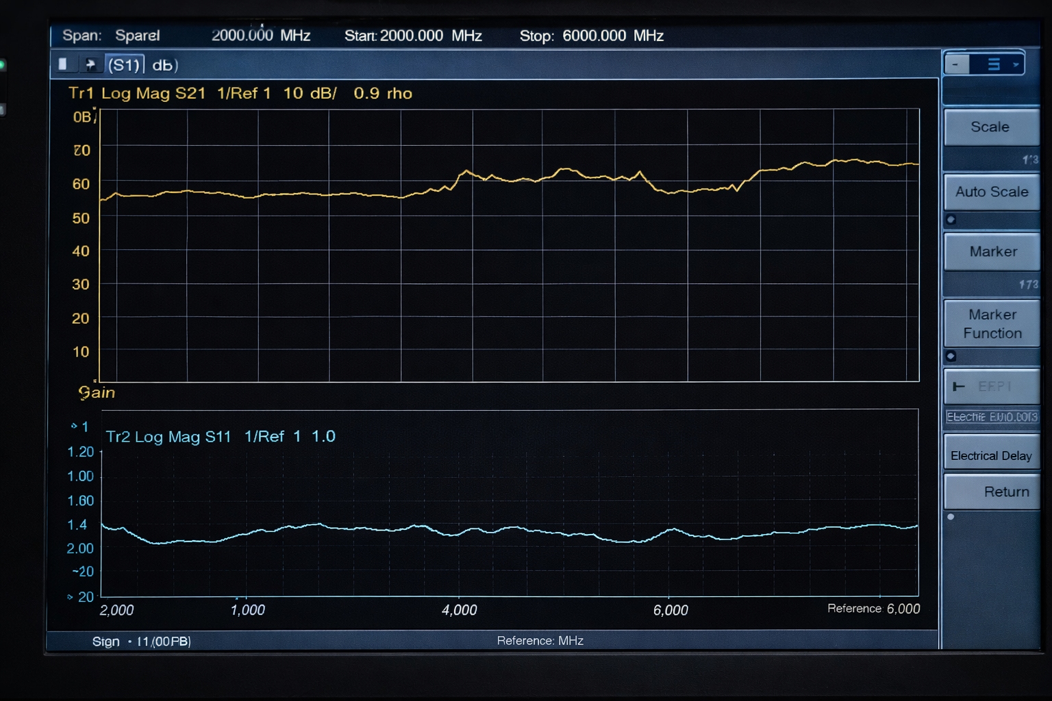
For authorized C-UAS, EMC, SDR and controlled RF test programs, the risk is rarely one loose component. The real risk is whether the signal source, RF power amplifier, filtering, antenna path, protection logic and cooling plan work as one front-end platform.
| Buyer question | Why it matters | CorelixRF review output |
|---|---|---|
| Will the RF front end stay stable across the target band? | Unstable gain, mismatch or thermal drift can turn a lab demo into a field failure. | Band plan, amplifier class, gain margin and thermal review before quotation. |
| Can the platform be documented for an authorized program? | Government, security and test buyers usually need traceable configuration details. | Configuration notes, interface assumptions, test items and RFQ checklist. |
| Is this a standard module purchase or a system-level build? | Buying only a PA may miss filtering, antenna, cooling and control requirements. | Recommendation path to standard RF front-end, custom RF system or product module. |
CUSTOM RF SYSTEMS TRUST PATH
Custom RF systems require buyers to align the source, amplifier, filter, antenna, control, cooling, enclosure and documentation path. CorelixRF uses factory review and test evidence to turn early requirements into a quotable RF front-end plan.
Start with standard or modified RF power amplifier platforms where possible.
RF amplifier platformsConnect SDR source and antenna assumptions before mechanical or rack decisions.
SDR source moduleUse case profiles, delivery documents and testing records to reduce supplier risk.
Case profiles