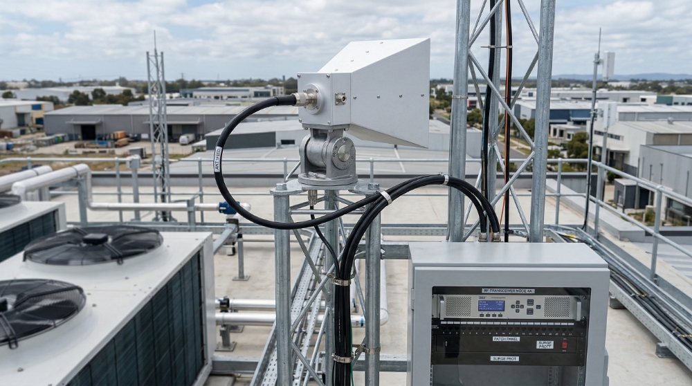
2.4 GHz Omnidirectional Chain
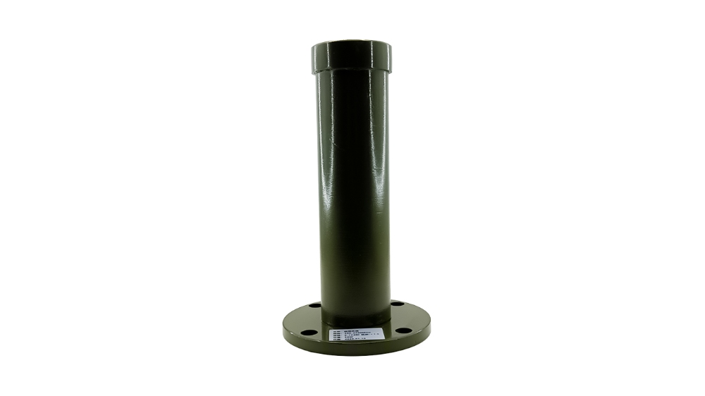
A frequency-matched path built around a 2.4 GHz amplifier stage and a corresponding omnidirectional antenna. Suitable when broad horizontal coverage is required at this band.
Direct RF Manufacturer for Signal Transmission Systems
CorelixRF supports project-based RF signal transmission paths built around SDR source modules, CW RF power amplifiers, and matched antenna or load output architectures — with frequency, power, interface, cooling, connector, enclosure, and antenna-path customization available for OEM integration projects.
Factory-coordinated source, amplification, output matching, customization review, and validation support help reduce integration risk before hardware selection.

Built for engineers, integrators, and project teams that need a matched signal source, CW RF amplifier, and antenna or load output path instead of isolated components from multiple suppliers.
Need source, amplifier, antenna, load, and enclosure-level matching before platform integration.
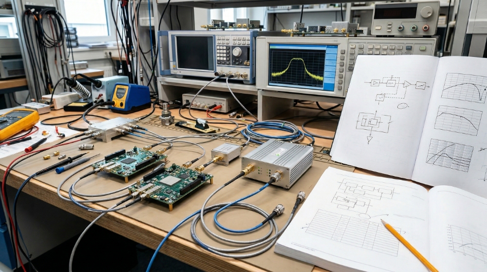
Need a clearer signal transmission path for bench testing, validation, and system-level review.
Need flexible signal generation paired with deployable CW amplification and output matching.
Need one factory-side coordination point to reduce supplier mismatch and evaluation delays.
These project types often require more than individual RF components. They require a clearer definition of the full transmission path before hardware selection and system integration can move forward efficiently.
Many RF signal transmission projects slow down because the source, amplifier, antenna, load, thermal path, and interface conditions are not reviewed together early enough.
SDR or signal source output may need practical amplification before real antenna, load, or system-level testing.
A wide signal source does not mean one RF power amplifier can cover the full planned range at the required power.
VSWR, load mismatch, connector path, cable loss, and output power handling can affect reliability.
CW operation requires practical cooling, mounting, DC input, airflow, and enclosure planning before hardware selection.
Source, PA, antenna, and load-side issues become harder to diagnose when responsibility is split across vendors.
Match the required RF signal path with practical amplifier frequency coverage and output power.
Review source level, amplifier gain, output stage, connector path, and antenna or load condition together.
Bring mismatch, load protection, cable, connector, and output architecture risks into the early discussion.
Reduce repeated re-selection by coordinating source, PA, output path, thermal, control, and documentation requirements.
System Architecture
RF signal transmission is not only one module. It is a coordinated path from signal source or SDR, through CW RF amplification, into an antenna, load, or system output stage. Successful project delivery depends on frequency matching, output power, load condition, thermal planning, interface control, and installation constraints.
The source layer defines frequency, waveform, output level, signal behavior, and control flexibility across the transmission path.
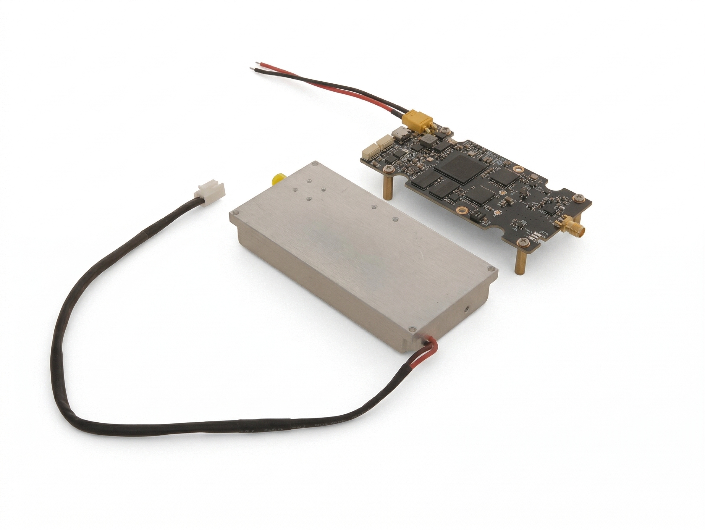
The amplifier layer raises the signal to the required RF output power through band-matched CW RF power modules and practical protection design.
The antenna or load stage determines how RF energy is delivered, tested, absorbed, or deployed in the final system path.
This layer includes DC input, cooling, mounting, cables, connectors, monitoring, control interface, enclosure fit, and documentation readiness.
Platform Paths
A wide SDR source or signal plan still requires band-matched CW RF amplification. Start from a standard platform path, then review frequency, power, interface, cooling, connector, antenna, and enclosure customization when the project requires it.
Low-band / UHF RF signal transmission path for platform, lab, and integration projects.
View PathMulti-band RF output and integration path for wider low-to-mid-band coverage.
View PathExtended CW amplifier path for RF signal transmission up to 2.7 GHz.
View PathSDR-compatible upper-band path for RF test, communication, and OEM integration.
View PathHigh-frequency CW amplifier review for advanced RF output applications.
View PathUltra-high-frequency amplifier review for higher-band RF transmission projects.
View PathStart from standard models and engineering baselines before customization.
View PathReview non-standard frequency, output power, interface, connector layout, cooling, enclosure, and control customization.
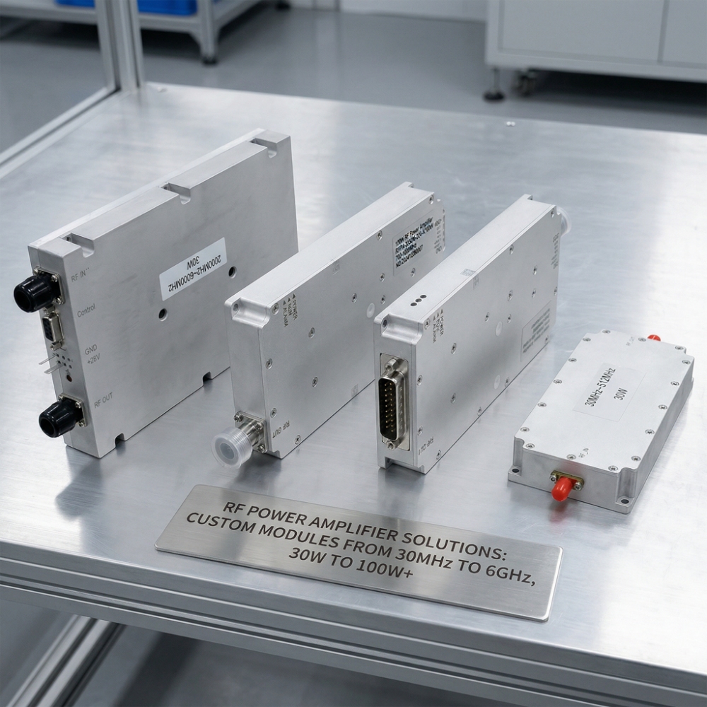
Discuss Custom PathCorelixRF structures RF signal transmission projects around band-matched RF power blocks rather than presenting the system as one universal full-band high-power unit. These examples show how practical CW amplifier blocks can support source, antenna, or load-side review.
These examples are not the full product range. They show how RF signal transmission projects are usually built around band-matched amplifier blocks.
| Frequency Range | Module Type | Output Power | Monitoring | Typical Application |
|---|---|---|---|---|
| 500–700 MHz | DDS RF PA Module | 200 W | RS485 | Sub-band transmission chain |
| 1000–1300 MHz | DDS RF PA Module | 200 W | RS485 | Mid-band RF output system |
| 2400–2485 MHz | DDS RF PA Module | 150 W | RS485 | 2.4 GHz omnidirectional chain |
| 5150–5350 MHz | DDS RF PA Module | 50 W | RS485 | Compact 5.2 GHz chain |
| 5725–5875 MHz | DDS RF PA Module | 150 W | RS485 | 5.8 GHz omnidirectional chain |
Additional band, power, interface, cooling, enclosure, and output combinations can be reviewed based on project-specific RF signal transmission requirements.
Flexible signal generation is the foundation of a configurable RF signal transmission path.
CorelixRF’s SDR source layer provides the frequency flexibility needed for project-based RF signal transmission paths. A source module covering 100 MHz to 6000 MHz with dual independent outputs creates a practical foundation for systems that require adjustable center frequency, configurable output behavior, and coordination with different RF amplifier stages.
In RF signal transmission design, source flexibility is valuable not because it solves everything alone, but because it makes wider system matching possible across multiple downstream CW PA options. In many projects, source flexibility directly affects how the rest of the RF signal transmission path is structured and evaluated.
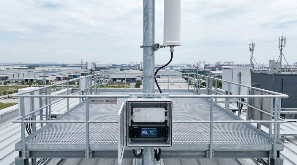
Omnidirectional, directional, antenna, and load-side output paths solve different signal transmission problems.
Use an omnidirectional architecture when the project requires horizontal area coverage across surrounding directions. This output path is often suitable for platform-mounted, vehicle-mounted, or site-level RF transmission where broad coverage matters more than concentrated energy.
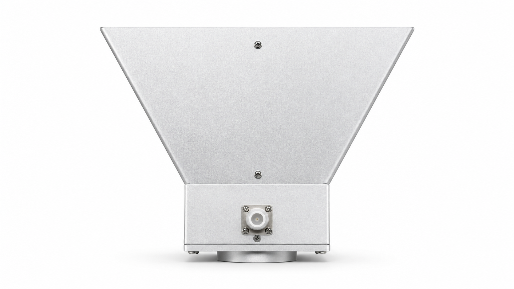
Use a directional architecture when the system needs to focus RF energy toward a defined area, sector, or path. This output path is often suitable when higher effective output in one direction is more important than broad surrounding coverage.
Engineering Intake
The more clearly these conditions are defined, the faster CorelixRF can recommend a practical signal source, CW amplifier, and antenna or load output path.
Confirm the exact operating band or tuning range instead of only a general application name.
Define the target CW output power at the amplifier output or after cable / antenna path losses.
Clarify continuous operation, test duration, duty cycle, and expected thermal load.
Share SDR or signal source output level so gain and drive margin can be reviewed.
Confirm whether the output connects to an antenna, dummy load, DUT, cable network, or system input.
Review load-side mismatch, reflected power risk, connector path, and protection expectations.
Define supply voltage, current limit, connector style, and power budget constraints.
Confirm fan cooling, conduction cooling, airflow direction, heat sink, or enclosure thermal path.
Clarify enable, monitor, RS422 / RS485, alarms, and system control requirements.
Share mechanical limits, mounting surface, connector direction, and OEM packaging needs.
Typical ways source, CW amplification, and output stages can be combined into practical RF signal transmission paths.
These examples are reference paths rather than fixed product bundles. Final configurations should be reviewed based on target frequency, required output power, source level, output architecture, load condition, cooling, and integration constraints.
A frequency-matched path built around a 2.4 GHz amplifier stage and a corresponding omnidirectional antenna. Suitable when broad horizontal coverage is required at this band.
A band-aligned output path using a 5.8 GHz amplifier stage and matched omnidirectional output. Suitable for projects that prioritize consistent frequency matching.
A more compact high-band path where lower output power and smaller system size are more important than maximum transmission level.
A wider-output concept in which the source and antenna support broader frequency coverage, while the RF amplifier stage is selected according to the target band.
Standard platforms are the starting point, not the limit. CorelixRF can review project-specific adjustments when the required signal path cannot be solved by an off-the-shelf configuration.
For many RF signal transmission projects, standard modules provide a useful engineering baseline, but the final system path often requires adjustment. CorelixRF can review customization across the signal source, CW amplifier, antenna or load output path, control interface, connector layout, cooling method, and OEM enclosure conditions.
This helps project teams avoid forcing a standard module into a system where the frequency range, output power, duty condition, thermal path, interface, or mechanical structure needs a project-specific review.
Factory Capabilities
A RF signal transmission path should be supported by real engineering coordination, not only by product descriptions. CorelixRF structures project discussion around frequency path definition, module compatibility, output architecture, customization feasibility, and integration readiness.

Used to review output behavior, interface control, and protection awareness before project deployment.
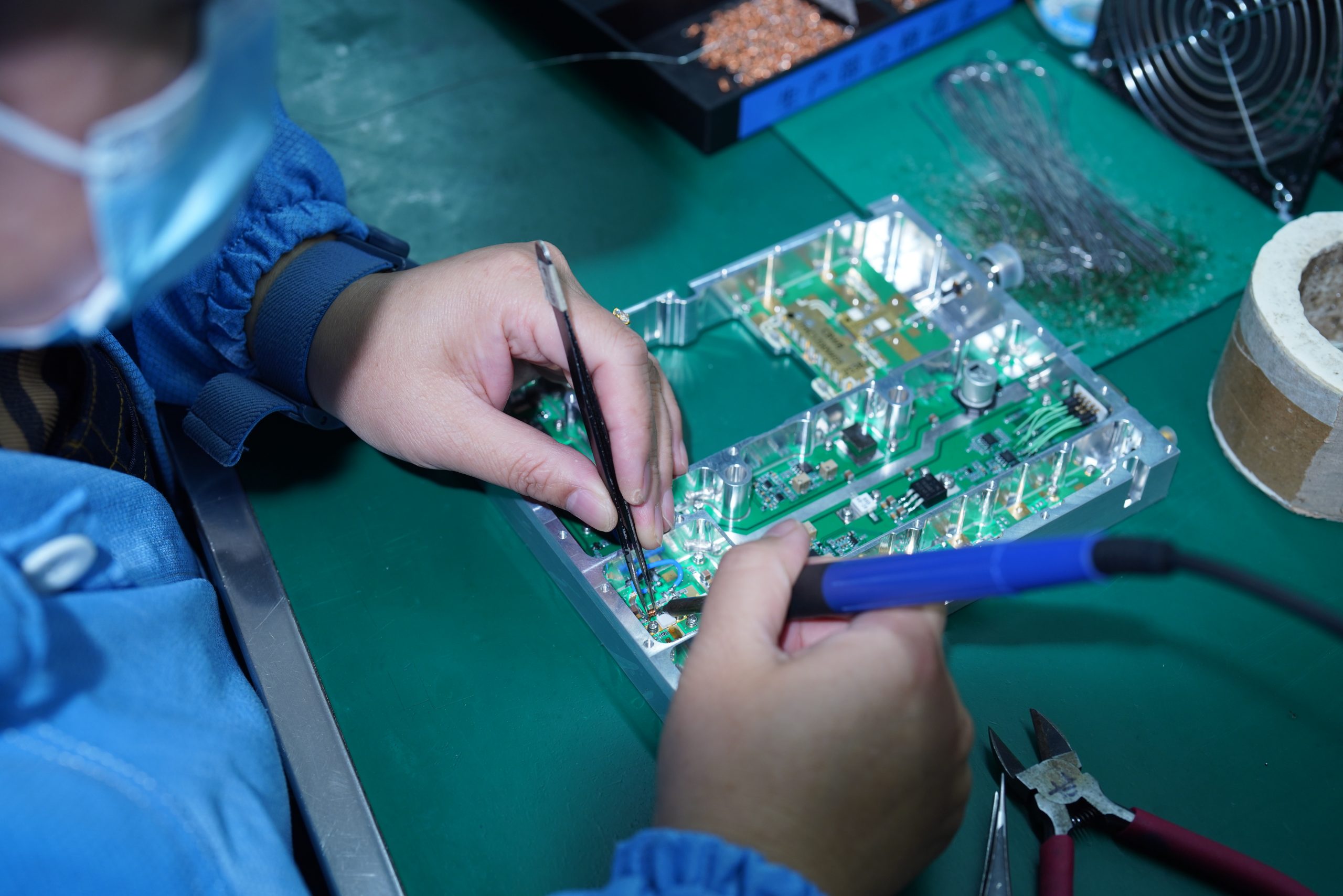
Supports consistent implementation of module structure, interface layout, and integration readiness.
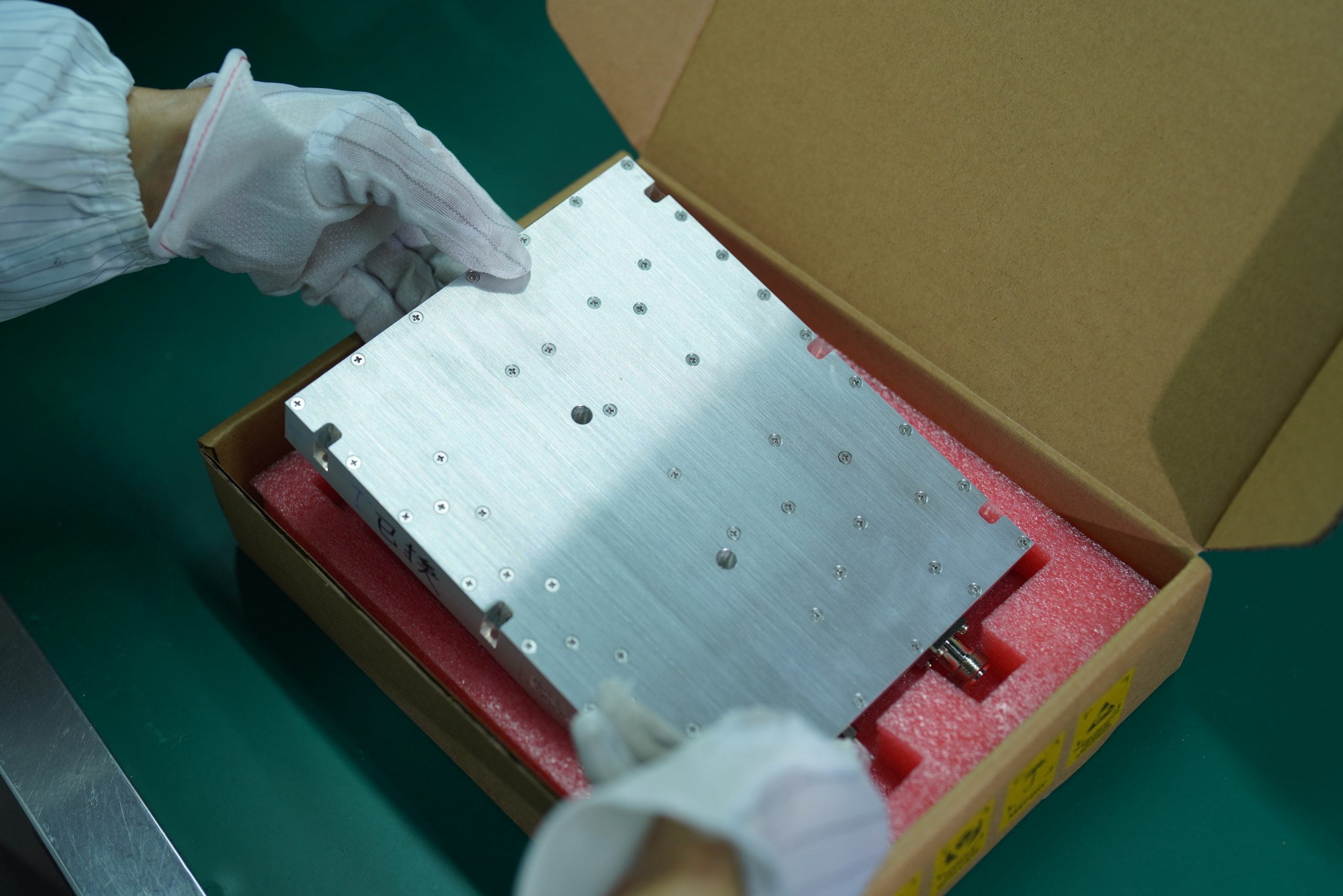
Helps project teams move from evaluation samples to clearer production and shipment coordination.
Less coordination risk, clearer matching logic, and a more practical path to deployment.
Separate Sourcing
Factory-Coordinated Solution
A structured RF signal transmission path architecture is useful across engineering, OEM, and deployment-oriented RF projects.
Suitable for projects where signal flexibility, testing convenience, and architecture visibility are important during development.
Useful when the platform needs to support more than one target band across a coordinated system structure.
Suitable for deployments where broad surrounding coverage is more important than directional concentration.
Suitable when the goal is to focus RF energy toward a defined area or transmission direction.
Useful for customers who need RF transmission building blocks that can be reviewed as part of a larger subsystem.
Suitable for project teams that need a more practical way to assess source, amplifier, and output combinations before deployment.
Next RF Path
If your project is not a standard CW signal transmission chain, choose the closest CorelixRF product path below. This keeps the application page focused while giving buyers a clear route into product-level evaluation.
Key answers buyers and engineering teams usually need before selecting a source, amplifier, antenna, or load output path.
No. It usually refers to the signal source, RF amplification, and antenna or load output path. Final platform integration still depends on the customer enclosure, power supply, cooling, cables, control logic, and deployment environment.
Yes. CorelixRF can review the target frequency, output power, SDR or source level, antenna or load condition, and integration constraints to recommend a practical RF signal transmission path.
Usually no. An SDR source may cover a wide frequency range, but high-power RF amplifiers are normally selected by practical operating band and output power.
Yes. CorelixRF can review only the amplifier stage or help match a CorelixRF amplifier with customer-provided source, antenna, load, enclosure, or control conditions.
Useful starting information includes target frequency range, RF output power, source output level, CW duty condition, antenna or load type, VSWR risk, DC input, cooling method, interface needs, and mounting space.
Yes. CorelixRF can review frequency range, output power, control interface, connector layout, cooling method, mechanical structure, antenna or load output path, documentation needs, and OEM enclosure requirements based on project needs.
Yes. Datasheets, interface information, typical test data, and selected validation records can be provided to support engineering review and procurement decisions.
Share your target frequency, output power, source condition, antenna or load type, cooling method, interface requirement, and installation limits. CorelixRF can review both standard platform options and project-specific customization paths.
In most cases, recommendation starts with target frequency, required RF output power, SDR or source level, antenna / load condition, DC input, cooling method, interface, and enclosure constraints — then moves into customization review when a standard path is not enough.
Engineering Intake
Use the CTA button to trigger your existing footer popup form. The intake can support both standard platform recommendations and custom RF signal transmission review.
Next Step
Send your frequency range, required RF power, SDR or source output level, antenna or load condition, cooling method, interface requirement, connector preference, and integration environment. CorelixRF will review standard options first, then evaluate customization where needed.
ALL INQUIRIES ARE TREATED AS CONFIDENTIAL. THE POPUP FORM IS CONTROLLED BY YOUR EXISTING FOOTER SCRIPT.