300–2700 MHz
RF Power Amplifier
Series
CRF-PA-300M2700M series covers 300–2700 MHz with 30W–200W standard output power options for RF testing, communication, and system integration projects.
Key datasheet-backed conditions used before model recommendation.
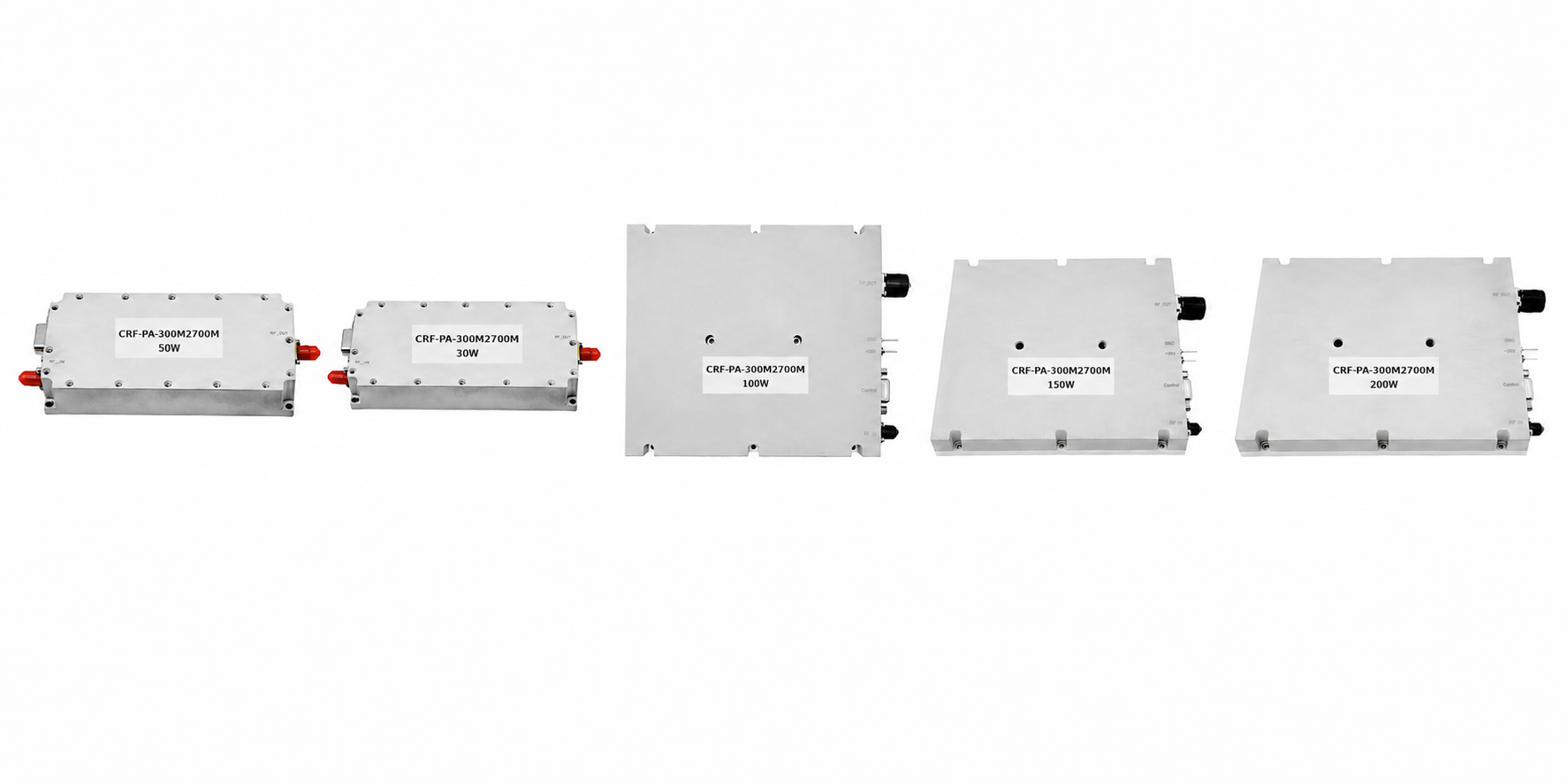
CRF-PA-300M2700M Standard Model Configurations
Use this table as a starting point. Final model recommendation depends on frequency range, output power target, operation requirement, cooling condition, load match, and integration details.
| Model | Power | Gain | Current | Size | Best For | Action |
|---|---|---|---|---|---|---|
| CRF-PA-300M2700M-30W | 30W | 44–46 dB | ≤4A | 125 × 59 × 21.5 mm | Lab evaluation / SDR driver | DatasheetReview |
| CRF-PA-300M2700M-50W | 50W | 46–48 dB | ≤9A | 125 × 59 × 21.5 mm | Compact RF chain | DatasheetReview |
| CRF-PA-300M2700M-100W | 100W | 49–51 dB | ≤18A | 200 × 158 × 25 mm | System integration | DatasheetReview |
| CRF-PA-300M2700M-150W | 150W | 51–53 dB | ≤20A | 200 × 158 × 25 mm | Broadband transmission | DatasheetReview |
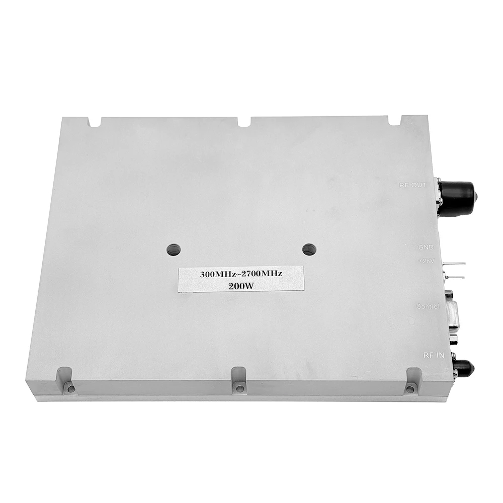
| CRF-PA-300M2700M-200W | 200W | 52–54 dB | ≤36A | 200 × 158 × 25 mm | High-power RF chain | DatasheetReview |
How to Choose the Right 300–2700 MHz RF Power Amplifier
Output power alone is not enough. A suitable RF amplifier depends on working band, output target, operation condition, cooling method, load match, and integration details.
Frequency Range
Confirm whether your system requires full 300–2700 MHz coverage or a narrower customized band. Custom frequency bands can be reviewed based on project requirements.
Output Power
Select a starting power level based on required RF output, cable loss, load condition, and system margin. Standard page comparison should follow datasheet-rated output power.
Output Type
The datasheet output power type is CW / Saturated. Pulse or duty-cycle-specific operation should be reviewed by engineering before recommendation.
Cooling
The standard cooling method is air cooling. Integration design should consider thermal contact, airflow, mounting surface, and enclosure structure.
Load Match
Input and output matching should be reviewed during RF chain integration. The datasheet includes input and output VSWR parameters for each model.
Mechanical Integration
Mechanical outline drawings are provided for dimensional review and connector location confirmation before installation.
Typical Applications for 300–2700 MHz RF Amplifier Integration
The datasheet application scope is RF testing / communication / system integration. The following cards convert that scope into practical RFQ review points.
RF Testing
For laboratory RF testing, broadband signal amplification, and amplifier evaluation platforms. Share frequency range, target output power, load condition, and test setup for review.
Send RF Test RequirementCommunication Systems
For communication systems requiring broadband RF output across 300–2700 MHz. Share frequency plan, output power target, operation condition, and integration environment.
Review Communication RequirementSystem Integration
For OEM or system-level RF chain integration where mechanical size, connector type, control interface, and thermal design need to be reviewed.
Start Integration ReviewSDR Front-End Integration
For SDR-based RF chains requiring a broadband amplifier stage after signal generation. Engineering review is recommended for gain response, output level, cooling, and load condition.
Send SDR Chain RequirementCustom RF Platform
For projects requiring custom frequency bands, connectors, control interfaces, or integration details. Feasibility review can be provided within 48 hours.
Request Custom ReviewBroadband RF Chain
For broadband RF chains that require model matching based on frequency, output power, cooling, and mechanical integration.
Request Platform ReviewWhy Engineering Review Matters Before Quotation
For broadband RF amplifier projects, frequency range and output power are only the starting points. A suitable recommendation also depends on operation type, cooling method, load condition, control interface, mechanical space, and integration details.
Standard Datasheet Configuration
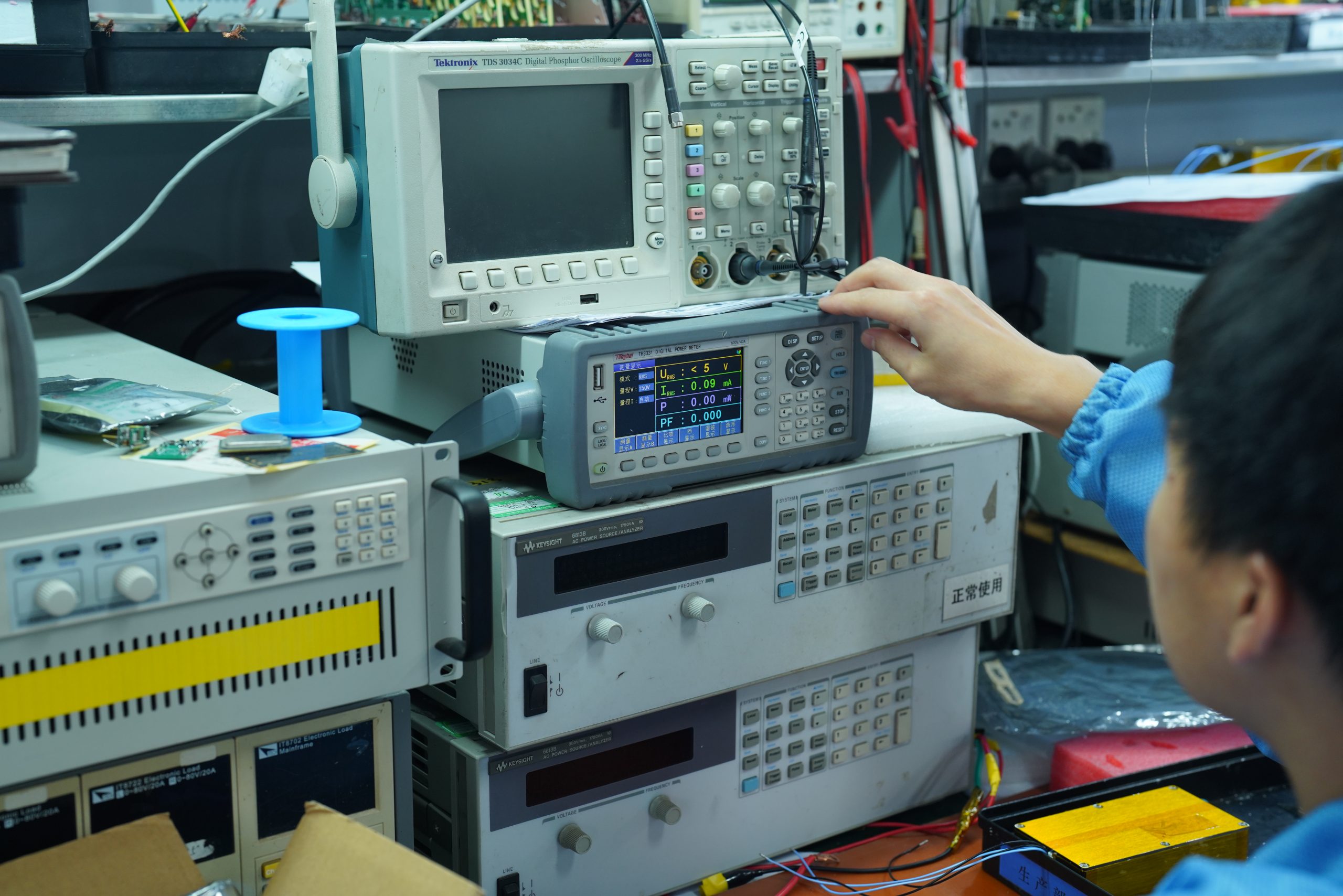
Typical Performance Curve and RF Validation
Each corresponding model datasheet includes a representative swept measurement of gain S21 and input match / SWR S11 versus frequency. Additional environmental and validation data can be supplied for project review where applicable.
Avoid adding unconfirmed page-level measured gain values. Use the corresponding model datasheet and project review data for exact validation discussion.
OEM / ODM Customization Support
Custom frequency bands, connectors, control interfaces, and integration details are available for project review. CorelixRF engineering team can provide feasibility review within 48 hours.
1. Requirement Review
Frequency range, output power, operation condition, cooling method, load condition, and application background.
2. Standard Model Matching
Compare the requirement against CRF-PA-300M2700M standard model options.
3. Customization Review
Review custom frequency band, connector, control interface, and integration details when standard configuration is not enough.
4. Mechanical & Interface Check
Confirm package size, connector location, DB9 control interface, RF input, RF output, and installation space.
5. Validation Data Review
Environmental and validation data can be supplied for project review where applicable.
Start OEM Review
Send frequency, power, operation requirement, cooling, connector, interface and mechanical constraints for evaluation.
Start OEM Amplifier Review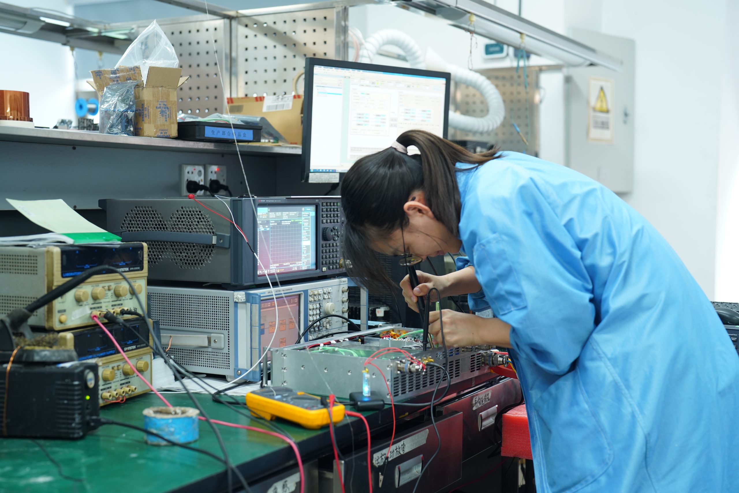
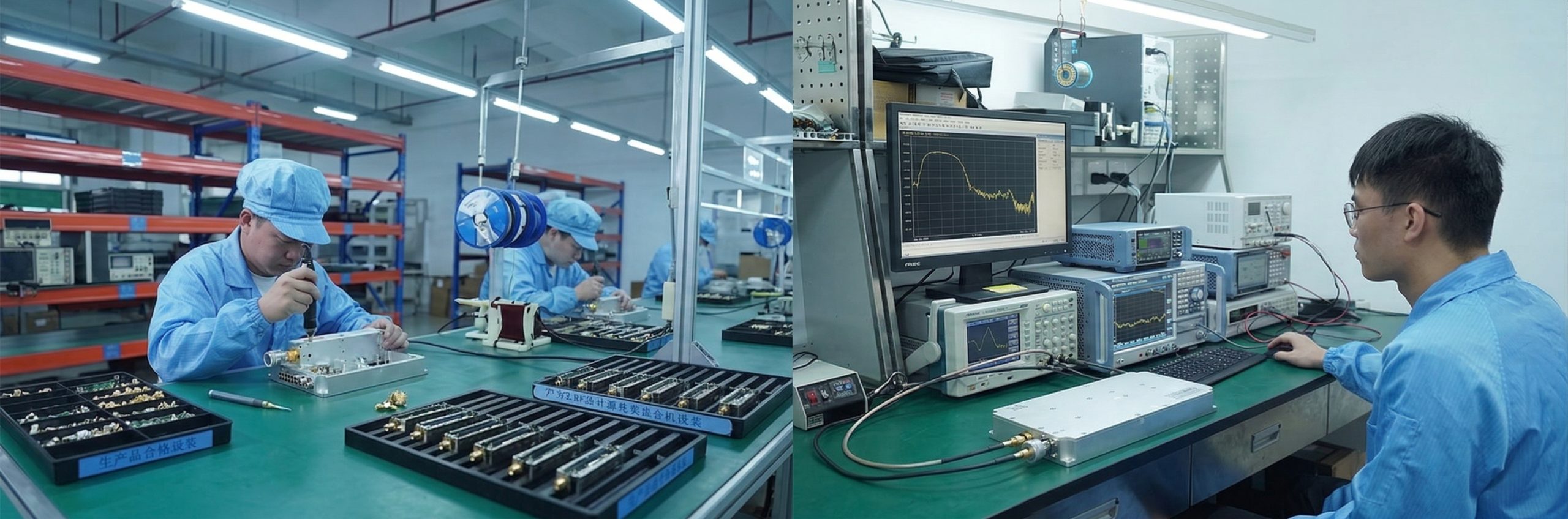
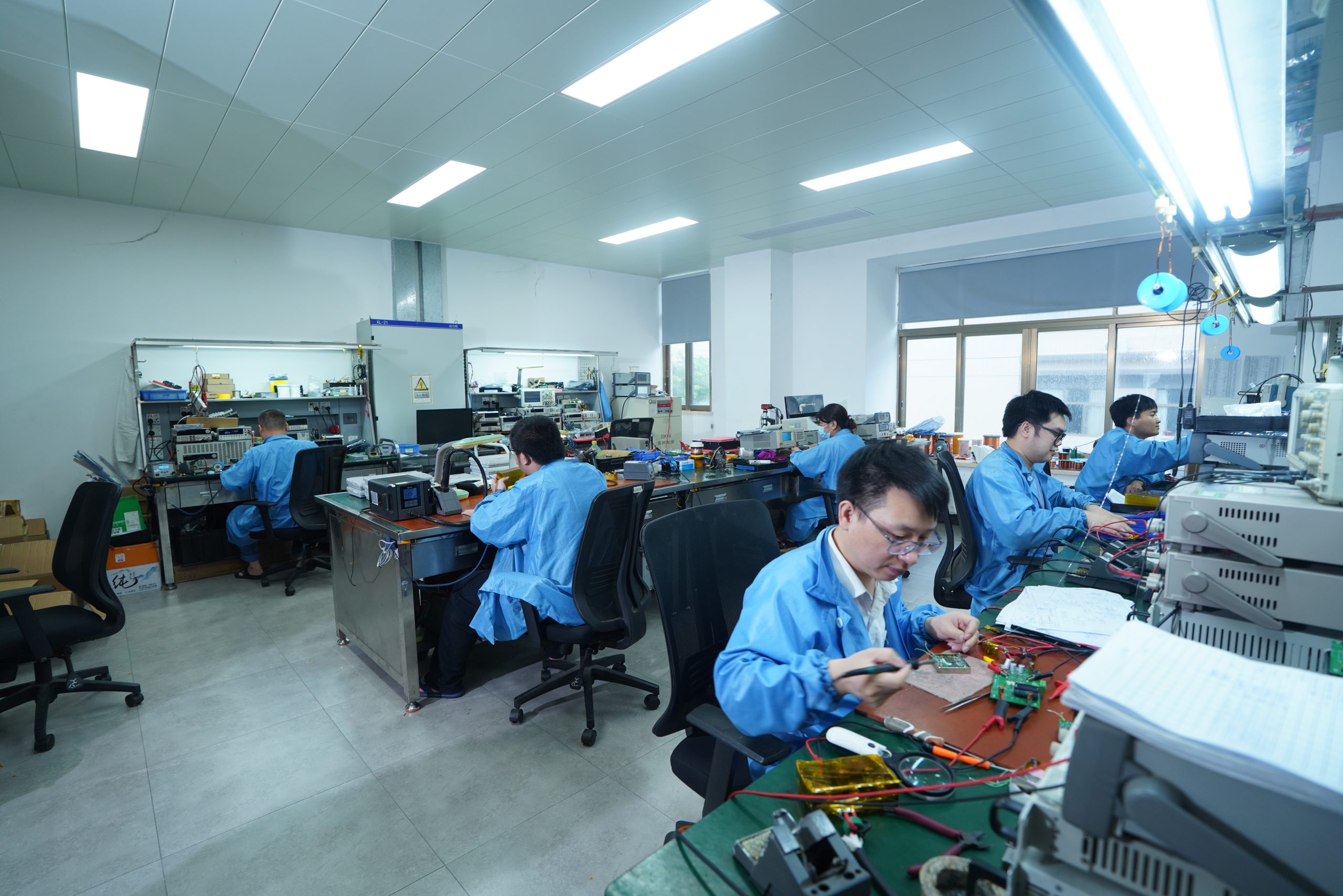
Manufacturing and Quality Control
Manufacturing content is kept as engineering support and quality-control evidence, while hard electrical parameters remain tied to the corresponding datasheet.
RF Assembly
RF path assembly, connector installation, and module-level preparation are handled according to controlled manufacturing procedures.
Mechanical Inspection
Package size, connector location, mounting surface, and mechanical outline are reviewed for integration reference.
RF Performance Review
Representative swept gain S21 and input match / SWR S11 data are included in corresponding model datasheets.
Quality Framework
RoHS Compliant, CE / FCC, ISO 9001, and GJB 9001C quality framework information is included in the datasheet.
Integration Considerations Before Model Selection
These review points help avoid wrong model selection before RFQ and mechanical integration.
Thermal Design
The standard cooling method is air cooling. High-power broadband operation should be reviewed with mounting surface, airflow, enclosure, and working time.
Load Match
Input and output VSWR parameters are listed in the datasheet. Cable, antenna, load, and system match should be reviewed during integration.
Mechanical Space
The 30W and 50W models use a 125 × 59 × 21.5 mm package, while the 100W, 150W and 200W models use a 200 × 158 × 25 mm package.
Control Interface
The standard control interface is DB9. Custom control interfaces can be reviewed based on project requirements.
300–2700 MHz RF Amplifier FAQ
Request RF Engineering Review
To recommend the right CRF-PA-300M2700M amplifier, please share your frequency range, output power, operation requirement, cooling condition, load condition, and integration details.