CorelixRF — Header Component (Enhanced + Fixed)
CW Amplifier + Antenna Systems | Matched RF System Manufacturer | CorelixRF
CorelixRF // Matched CW RF System Solutions

This Is a Matched CW RF System.
Not Separate Products.

CorelixRF delivers amplifier-led CW RF systems — wideband RF power amplifier platforms matched with omnidirectional or directional antennas into a single, factory-integrated signal path for communication, UAV-related platforms, RF testing and deployment projects.

Every system starts with your real frequency, CW output power and coverage requirement. We select the CW amplifier platform, confirm the antenna path, review connector and cable details, and deliver a matched RF system — not a parts list.

For antenna matching, CorelixRF uses CW amplifier platforms only. Pulsed RF amplifier projects follow a separate engineering review path because pulse width, duty cycle and timing behavior require different thermal and system validation.
CW Amplifier + Antenna Matching30 MHz–6 GHz Listed CW PlatformsUp to 200 W CW Platform ClassOmni + Directional Antenna PathsConnector / Cable / Power Handling Review24–48 hr Engineering Review Target
30 MHz
Starting point for listed CW amplifier platforms
6 GHz
Listed CW platform range for antenna matching
200 W
Up to 200 W CW platform class
4
CW amplifier platform paths
2 Paths
Omni + directional antenna matching
24–48 hr
Engineering review target
System Overview

What We Mean by CW Amplifier + Antenna Systems

We design amplifier-led CW RF systems, not just product combinations.

CorelixRF builds matched CW RF systems around one clear signal path: CW amplifier platform, connector and cable path, antenna selection, then real coverage requirement. The amplifier is not treated as a separate product from the antenna.

This page is for customers who do not want to buy an amplifier from one supplier, an antenna from another supplier, and then solve frequency overlap, power handling, connector and cable-loss questions alone.

CW Matching Scope
This page focuses on CW amplifier + antenna matching. Pulsed RF amplifier projects should be reviewed through the Pulsed RF Amplifiers page because pulse width, duty cycle and pulse frequency require a separate matching and thermal review.
Matched Signal Path

Signal → CW Amplifier → Cable → Antenna → Coverage

The system is reviewed as one RF chain, not as isolated parts from different suppliers.

01
RF Source / Signal InputDefines the working frequency and input condition.
02
CW Amplifier PlatformSelected by band and CW output class.
03
Connector + Cable PathReviewed for connector fit and frequency-related cable loss.
04
Omni / Directional AntennaMatched to coverage direction and power handling.
Step 01
Start with CW platform
30–512 MHz, 300–1700 MHz, 300–2700 MHz or 2–6 GHz platform path.
Step 02
Review antenna path
Omnidirectional for 360° coverage or directional for focused RF delivery.
Step 03
Check RF chain details
CW output power, antenna power handling, cable loss and connector type are reviewed together.
Step 04
Factory-backed delivery
Datasheet, matching notes, connector review and project support can be prepared after engineering review.

Not sure which path fits?

Send frequency, CW output power, antenna direction, cable length and connector preference for engineering review.

Ask for Matching Review →
Two Matched System Paths

Choose Your CW Amplifier + Antenna System Path

Each path is based on a CW amplifier platform matched with an antenna, connector, cable and integration plan. Select the configuration that fits your coverage requirement.

Omnidirectional antenna deploymentPath A
Amplifier + Omni Antenna · 360° matched system
Broad Coverage System

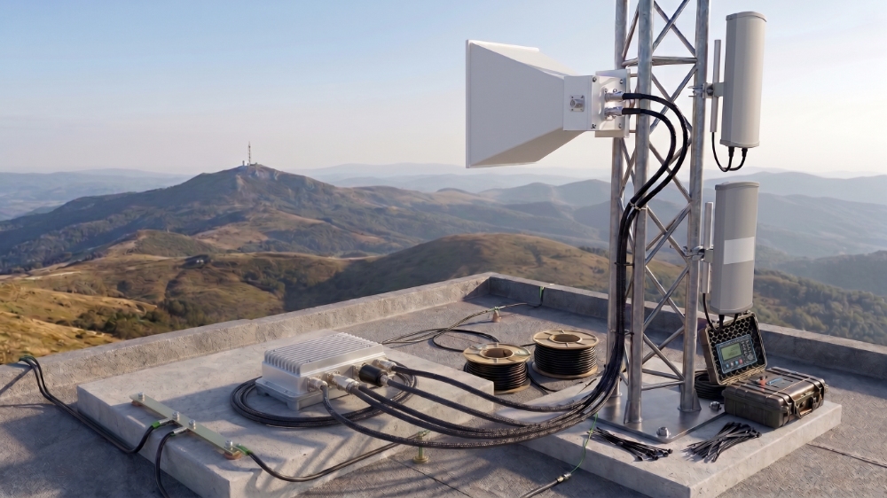
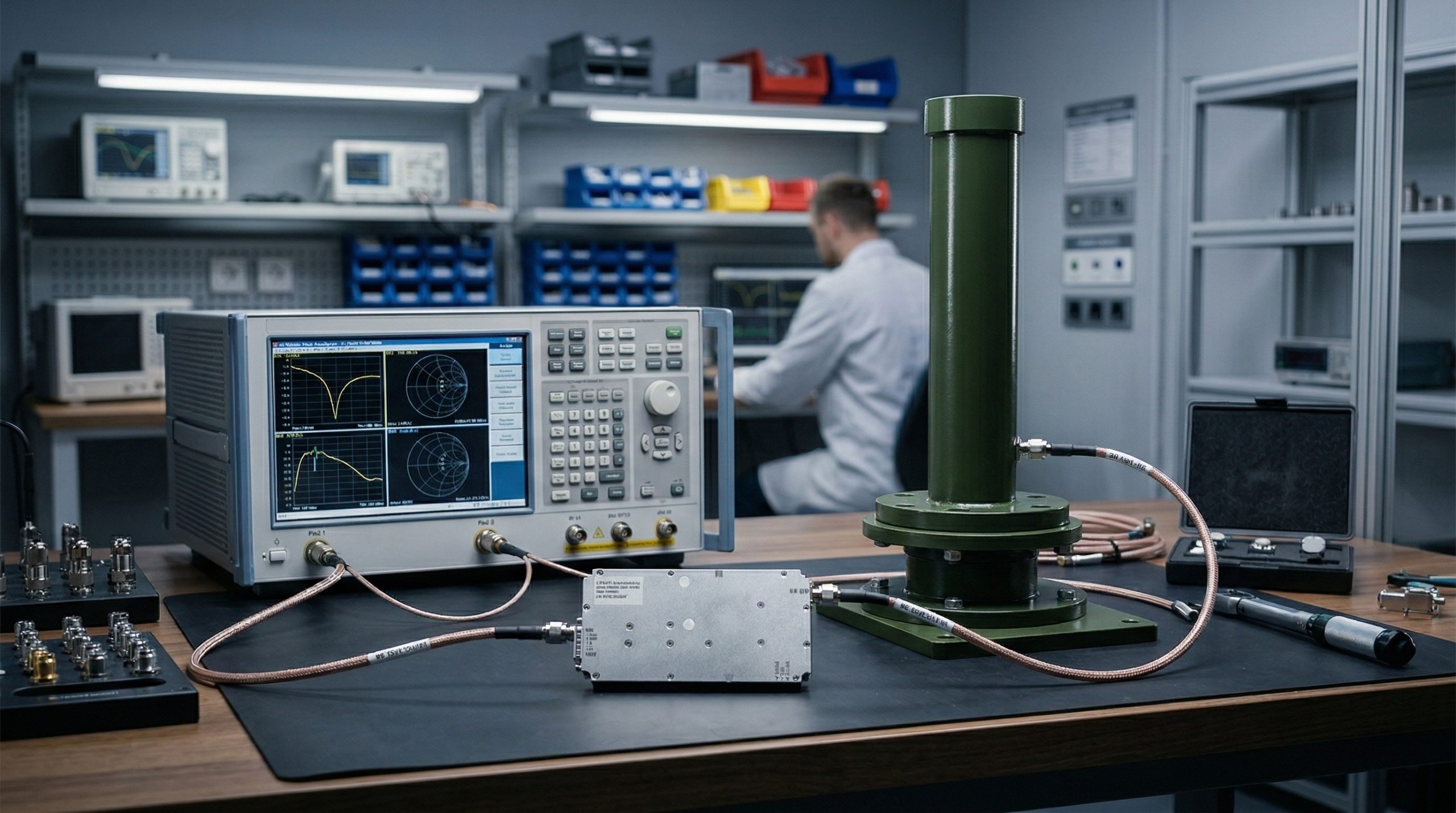
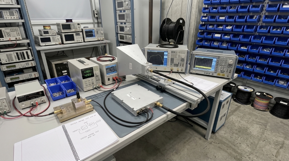
CW Amplifier + Omnidirectional Antenna System

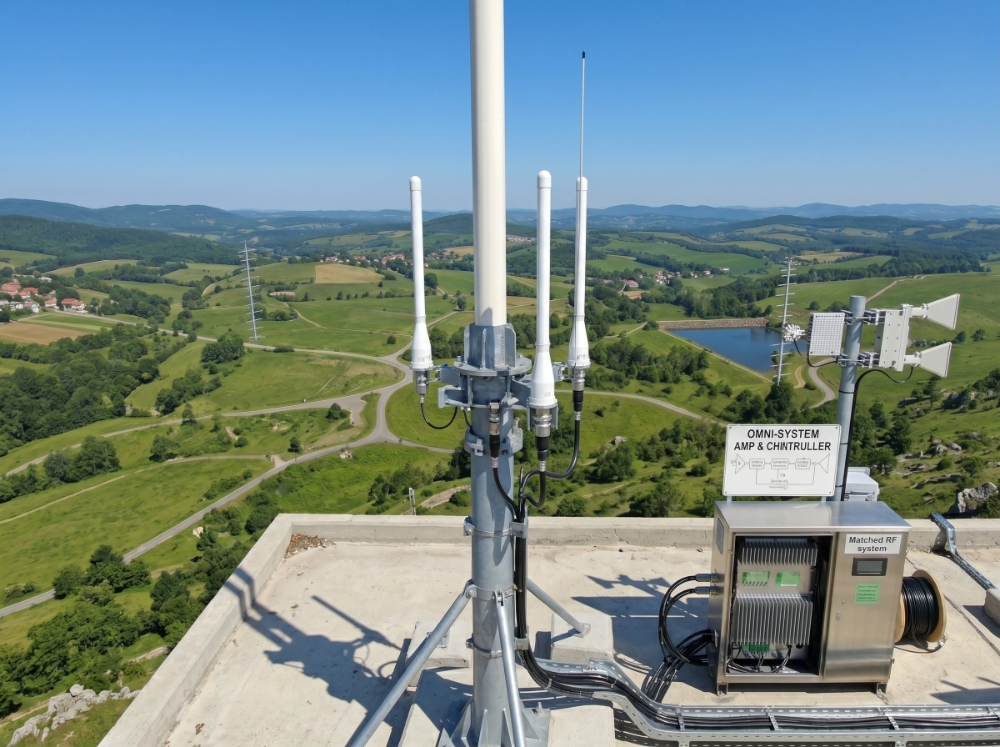
A matched RF system built for broad-area signal distribution. The CW amplifier platform drives an omnidirectional antenna across a 360-degree radiation pattern for mobile or fixed installations.

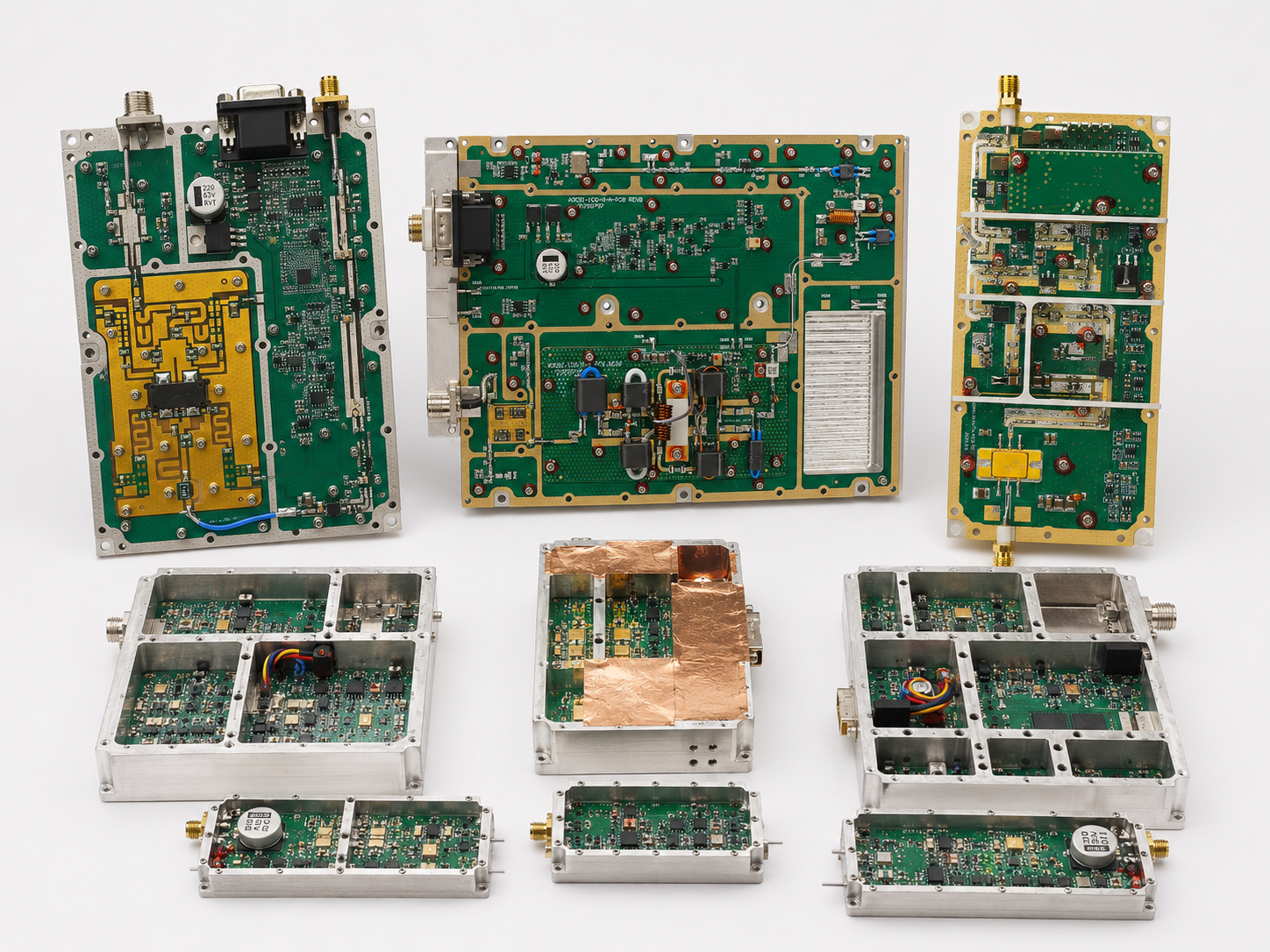
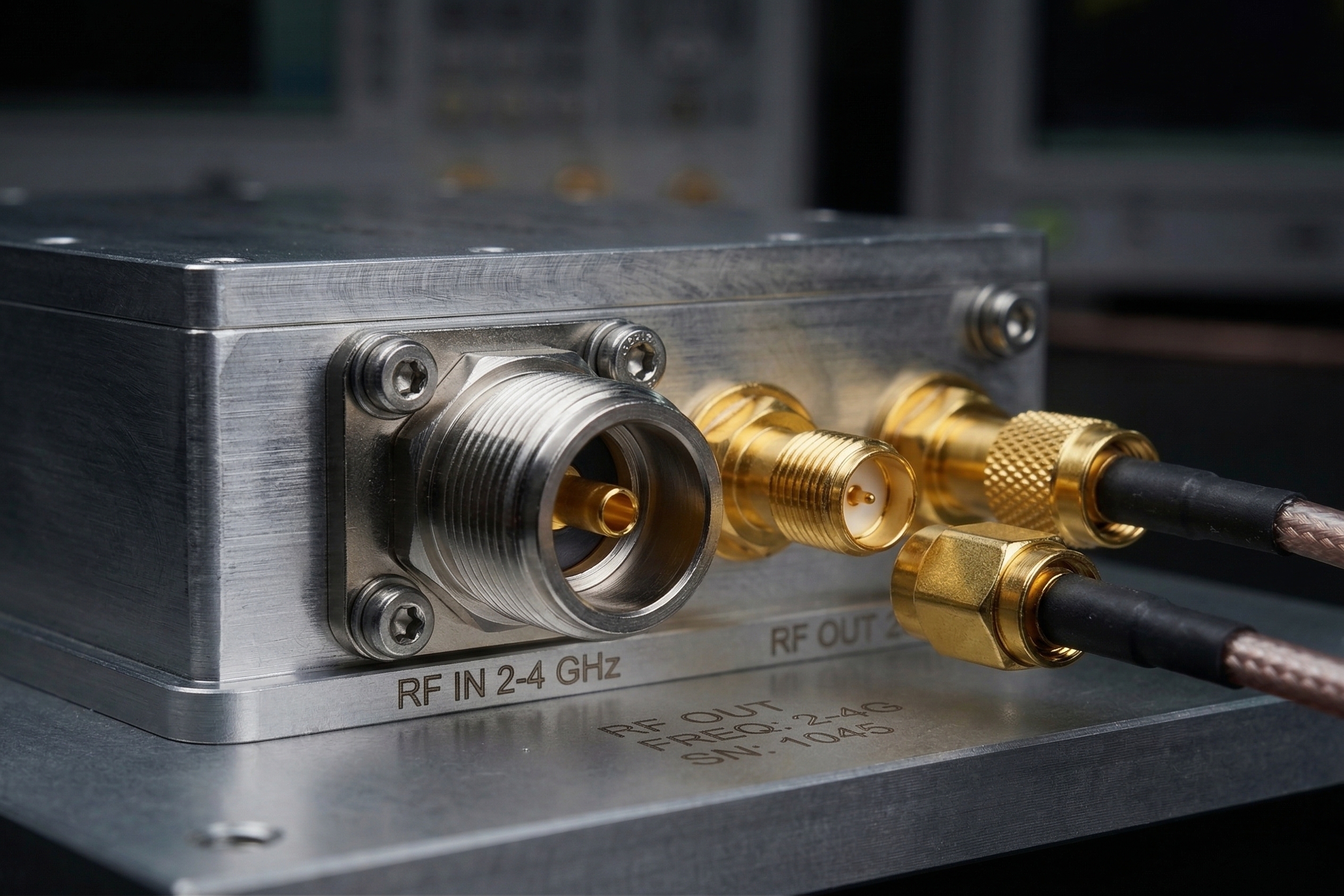
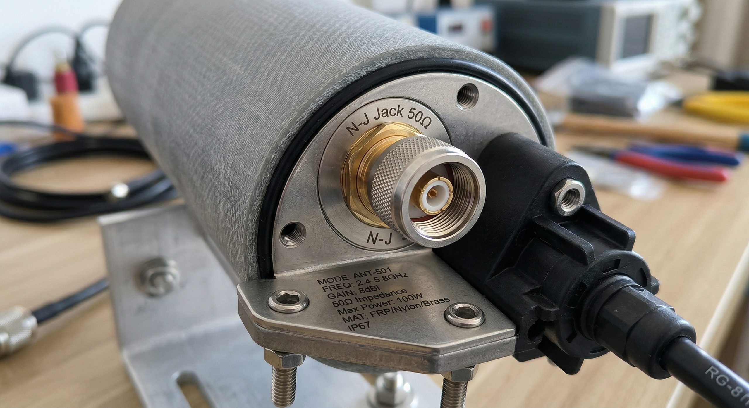
  • CW amplifier platform + omni antenna + matched cabling
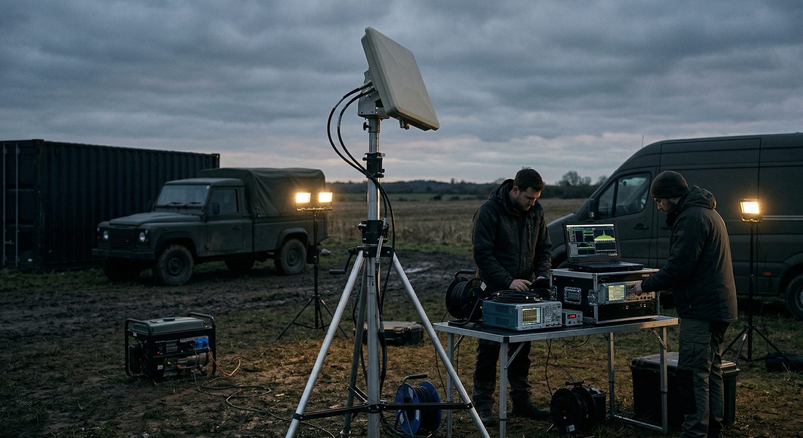
  • 360-degree radiation path without pointing alignment
  • Suitable for communication coverage and deployment projects
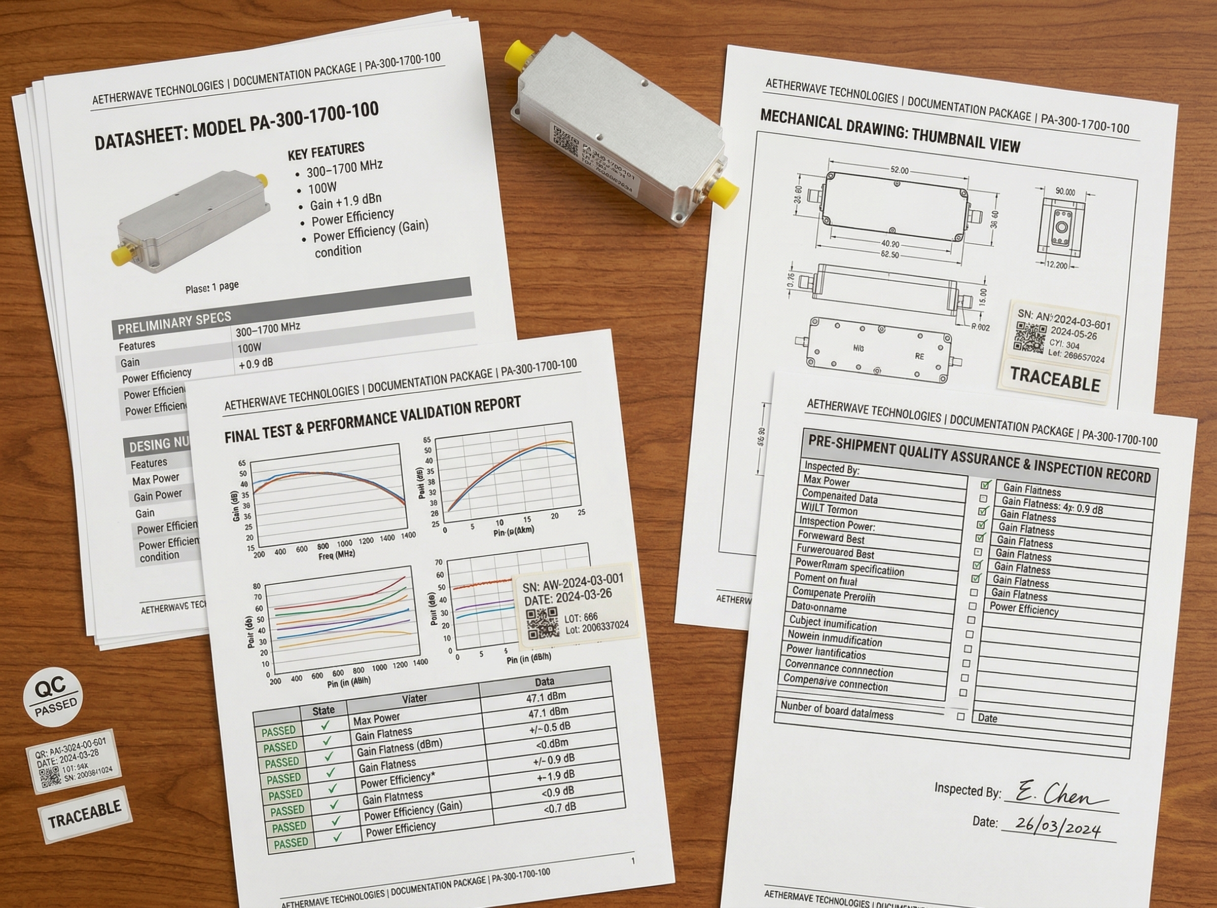
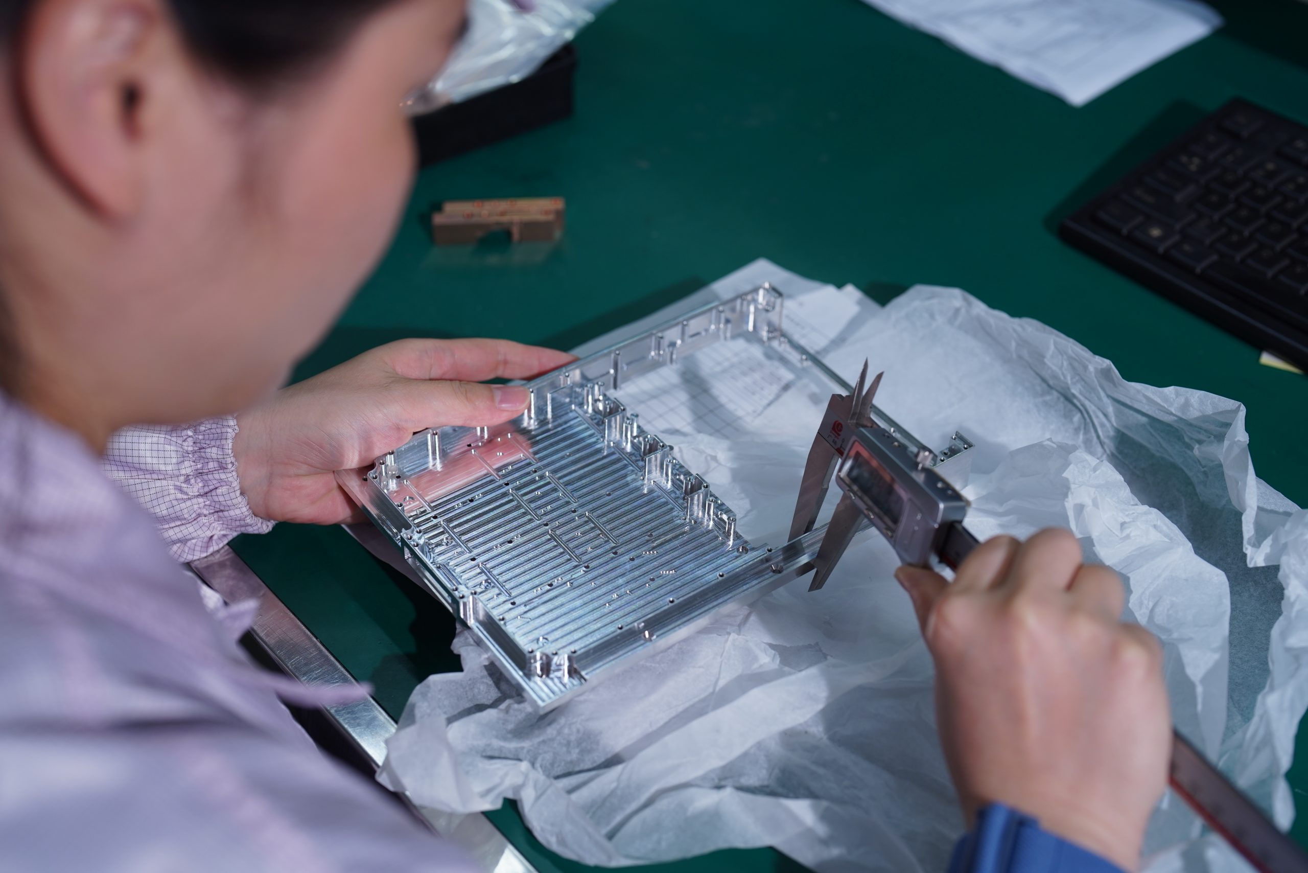
  • Connector and power handling reviewed before recommendation
Directional antenna system deploymentPath B
Amplifier + Directional Antenna · focused system
Focused Transmission System

CW Amplifier + Directional Antenna System

A matched RF system built for focused signal delivery. The CW amplifier platform drives a directional antenna along a defined transmission path for point-to-point, sector or test environments.

  • CW amplifier platform + directional antenna + matched cabling
  • Focused beam for gain and directionality control
  • Panel, horn and yagi antenna paths can be reviewed
  • Preferred for higher-frequency and defined-path systems
CW Amplifier Platforms for Matching

CW Amplifier Platforms Used for Antenna Matching

Only CW wideband amplifier platforms are used for amplifier + antenna matching on this page. Pulsed RF amplifiers are reviewed separately because pulse width, duty cycle and timing behavior require a different matching and thermal review path.

We do not start with an antenna catalog. We start with a CW amplifier platform. Every matched system CorelixRF delivers is built on one of the CW wideband amplifier platforms below — selected by your target frequency range, output power requirement and antenna path. Pulsed RF amplifier projects are reviewed separately.
System Platform 01
30–512 MHz
CW Amplifier System Base
CW Output Class
30 W50 W100 W150 W200 W
Low-frequency wideband coverage, communication integration and custom RF system builds. Matched with omni or directional antenna depending on application.
View Platform Specs →
System Platform 02
300–1700 MHz
CW Amplifier System Base
CW Output Class
30 W50 W100 W150 W200 W
Broadband RF systems and communication platform builds. Supports omni and directional antenna paths after frequency and power handling review.
View Platform Specs →
System Platform 03
300–2700 MHz
CW Amplifier System Base
CW Output Class
30 W50 W100 W150 W200 W
Extended coverage and multi-band integration projects where amplifier frequency window and antenna path must be reviewed together.
View Platform Specs →
System Platform 04
2–6 GHz
CW Amplifier System Base
CW Output Class
30 W50 W100 W150 W200 W
High-frequency RF systems and test setups. Directional antenna path is usually preferred, with connector and cable loss reviewed early.
View Platform Specs →
CW Platform-Based System Matching — Quick Reference
CW Amplifier Platform CW Output Class Typical Matching Use Antenna Path
30–512 MHz 30–200 W Low-frequency wideband coverage and communication integration Omni + Directional
300–1700 MHz 30–200 W Broadband RF systems and communication platform builds Omni + Directional
300–2700 MHz 30–200 W Extended coverage systems and multi-band integration Omni + Directional
2–6 GHz 30–200 W High-frequency RF systems and test setups Directional preferred

Amplifier + antenna matching is based on CW output power, frequency overlap, antenna power handling, connector type, cable loss and radiation path. Pulsed RF amplifier models are not included in this matching table.

Risk 01

Frequency Overlap Is Not Enough

The amplifier band and antenna band must overlap, but gain, VSWR and radiation behavior also matter.

Risk 02

Power Handling Must Be Higher

Antenna power handling should be reviewed against amplifier CW output class and expected cable loss.

Risk 03

Cable Loss Reduces Real Delivery

Coaxial cable type, length and frequency affect delivered RF power at the antenna input.

Risk 04

Connector Mismatch Delays Integration

N-type, SMA, DIN or custom connector paths should be confirmed before production.

Risk 05

Omni and Directional Behave Differently

Omnidirectional antennas support 360° coverage, while directional antennas focus RF energy into a defined path.

Separate Path

Pulsed Amplifiers Need Separate Review

Pulse width, duty cycle, pulse frequency and timing behavior require a different engineering path.

Matching Inputs

What We Need to Match Your CW Amplifier + Antenna System

You do not need a complete system drawing to start. These inputs are enough for CorelixRF to review the first CW amplifier platform and antenna path.

Target Frequency Range
Start and stop frequency, working band or preferred platform path.
Required CW Output Power
CW output class, margin requirement and whether power must hold across band.
Omni or Directional Coverage
360° coverage, sector path, point-to-point or test setup requirement.
Antenna Power Handling
Known antenna rating or request for antenna recommendation.
Connector Type
N-type, SMA, DIN or other RF connector requirements.
Cable Length / Cable Loss
Cable type, approximate length and frequency-related loss concerns.
Installation Environment
Vehicle, fixed site, lab bench, enclosure or outdoor deployment.
Quantity / Project Stage
Prototype, validation, batch purchase or OEM integration project.
In-House Capability Chain
From CW Platform Review to Factory-Backed Delivery
CW PlatformAntenna PathConnector / CablePower HandlingRF TestingProject Delivery
Why Build Around CorelixRF

Factory Matching Support That Reduces Integration Risk

Component availability alone is not enough. What matters is whether the supplier can review CW amplifier platform, antenna path, power handling, cabling, documentation and practical integration from the same factory.

RF amplifier development lab
01

CW Amplifier Platform Review

Select the proper 30–512, 300–1700, 300–2700 or 2–6 GHz CW platform before antenna matching.

Platform First
RF test laboratory with measurement equipment
02

Antenna Path Confirmation

Review whether the project needs an omnidirectional coverage path or a directional transmission path.

Antenna Match
CNC machining and production line
03

Power Handling Check

Review amplifier CW output class against antenna power handling and cable loss before recommendation.

CW Power
RF customization engineering
04

Connector and Cable Matching

Confirm RF connector type, cable length, routing and frequency-related loss before production.

RF Chain
Technical documentation and engineering drawings
05

Datasheet / Test Data Support

Provide suitable datasheets, matching notes or test references after engineering review where applicable.

Documentation
Engineering support team
06

OEM / ODM Project Support

Support enclosure, mounting, connector position, control interface and project-based supply needs.

Factory Support
Typical Applications

Where CW Amplifier + Antenna Systems Are Deployed

These application directions use CW amplifier platforms matched with omni or directional antenna paths. Your project may combine several conditions.

UAV drone RF deployment
UAV Related

UAV Communication & Control

CW amplifier + antenna paths for UAV-related communication, control and support systems.

Request System Matching →
RF testing bench and measurement lab
RF Test

RF Test and Validation Setups

Bench and lab systems where amplifier power, antenna path and connectors must be reviewed together.

Request System Matching →
Communication system deployment
Communication

Fixed Communication Sites

CW RF systems for fixed-site, platform-level or engineering validation projects.

Request System Matching →
RF coverage deployment system
Deployment

Mobile RF Coverage Systems

Omni or directional antenna paths for mobile deployment and broad-area RF coverage projects.

Request System Matching →
Custom Options

Custom CW Amplifier + Antenna System Options

Standard CW platforms are starting points. Most integration projects involve adjustments to frequency window, output class, antenna type, connector path, monitoring or housing.

01

Frequency Window

Review the listed platform range or a narrower working band for better system fit.

02

CW Output Power Class

Match the amplifier output class with antenna power handling and cable loss.

03

Antenna Type and Gain

Select omni, panel, horn, yagi or other directional antenna paths according to coverage need.

04

Connector and Cable Path

Confirm connector type, cable length, cable loss and routing requirements.

05

Control Interface / Monitoring

Review monitoring, control interface and system communication requirements where applicable.

06

Housing / Mounting / OEM Format

Adapt enclosure, mounting, labeling and integration details for OEM or deployment projects.

Submit CW System Requirement
RF connector panel SMA N-type close-upConnector path review
Amplifier housing and mounting structureHousing / mounting review
RF cable routing and chain assemblyCable routing and RF chain assembly
Project Workflow

From Requirement Review to Matched System Delivery

A CW amplifier + antenna system begins with frequency, power and coverage. CorelixRF then reviews the matched RF chain before recommendation.

01

Requirement Review

Confirm frequency range, CW output power, coverage path and application environment.

02

CW Platform Selection

Select 30–512, 300–1700, 300–2700 or 2–6 GHz CW platform path.

03

Antenna Path Matching

Review omni or directional antenna type, gain and radiation path.

04

Connector / Cable / Power Review

Confirm connector, cable loss and antenna power handling before recommendation.

05

Factory Confirmation & Delivery

Provide suitable documentation, matching notes and delivery coordination.

Continue the Right Path

Continue from CW Amplifier + Antenna Systems to the Right CorelixRF Path

If your project needs a separate amplifier, antenna, SDR source or pulsed RF platform, continue to the related CorelixRF product path.

Use these entries when the matched CW system page is not the exact starting point for your project.
Frequently Asked Questions

CW Amplifier + Antenna System Questions

Are pulsed RF amplifiers included in amplifier + antenna matching?+

No. This page focuses on CW amplifier + antenna matching. Pulsed RF amplifiers are reviewed separately because pulse width, duty cycle, pulse frequency and timing behavior require a different engineering and thermal review path.

CorelixRF uses listed CW wideband amplifier platform paths including 30–512 MHz, 300–1700 MHz, 300–2700 MHz and 2–6 GHz for amplifier + antenna matching.

We review frequency overlap, CW output power, antenna power handling, VSWR, connector type, cable loss, radiation path and installation environment.

Yes. Omnidirectional antennas are typically used for 360° coverage, while directional antennas are used for focused transmission paths.

Yes. Connector type, cable path, control interface, mounting structure and OEM housing can be reviewed for project-based integration.

Frequency range, CW output power target, antenna direction, cable length, connector preference, quantity and application scenario are enough to begin.

Request a Recommendation

Need a CW Amplifier + Antenna System Matched to Your Frequency and Coverage?

Send your target frequency range, required CW output power, antenna direction, cable length, connector preference and application scenario. CorelixRF will review the suitable CW amplifier platform and antenna path for your project.

Frequency range · CW power target · antenna type · cable length · connector preference · application notes

CW platform matching — based on 30–512, 300–1700, 300–2700 or 2–6 GHz paths

Antenna path review — omnidirectional or directional according to coverage need

Connector and cable check — reduce integration mismatch before production

Power handling review — match amplifier CW output and antenna capability

Documentation support — datasheets and matching notes after review where applicable