01 / FULL BAND
Full-band output power is not always guaranteed
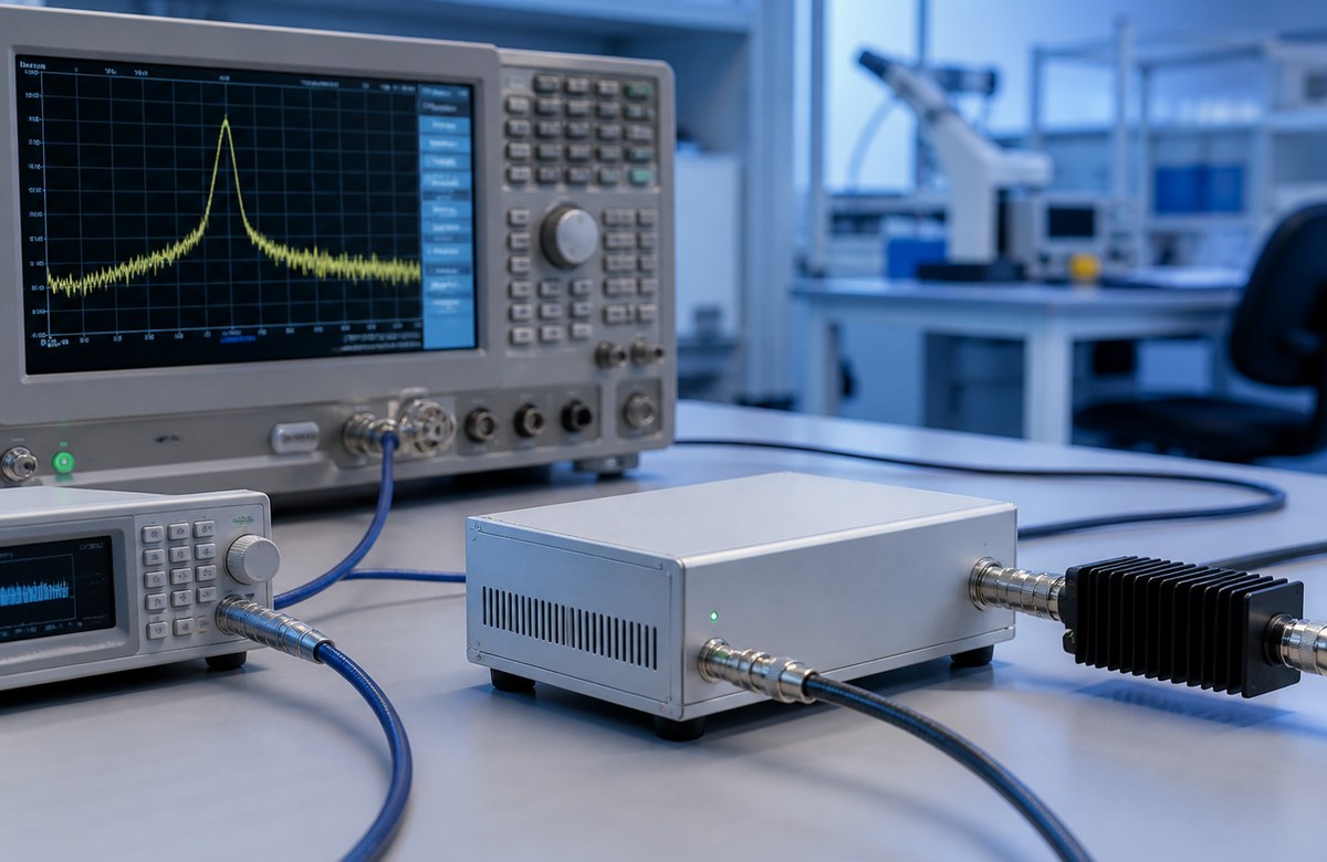
EMC testing cannot rely on one peak data point. Output power must be reviewed across the required frequency range and under realistic load conditions.
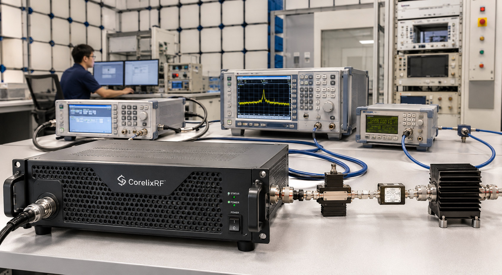
Factory-direct EMC RF amplifier platforms for laboratory, compliance and RF immunity-related test environments. CorelixRF supports custom frequency range, output power, CW or pulse operation, cooling, protection logic, rack integration, control interface and unit-level RF test data review.
CorelixRF EMC amplifiers are designed for RF immunity, radiated immunity, compliance testing, and laboratory EMC test systems.
Use this page to compare typical EMC amplifier platform windows, then request engineering review when your required frequency, output power, CW/pulse condition, load environment or documentation package is project-specific.
In EMC-related test environments, amplifier selection is affected by full-band output power, reflected power risk, thermal stability, duty cycle and system-level integration details.
EMC testing cannot rely on one peak data point. Output power must be reviewed across the required frequency range and under realistic load conditions.
Chamber, antenna and fixture changes can create mismatch conditions. Protection logic and RF margin should be confirmed before platform selection.
High-power EMC runs require cooling structure, airflow, over-temperature protection and duty-cycle review instead of only checking nominal power.
RF connectors, control interface, rack size, power supply, mechanical layout and required test documentation should be confirmed early.
CorelixRF does not only provide a fixed amplifier model. We review the required EMC test conditions and configure the platform around frequency, output power, cooling, control, protection and validation data.
 Engineering review before recommendation
Configure low-frequency, UHF, broadband GHz and microwave amplifier platforms based on required band, output level and test environment.
Review CW or pulse requirements, pulse width, duty cycle, timing behavior and thermal margin before selecting or customizing a platform.
Support air cooling, rack airflow, heat dissipation structure, VSWR protection, over-temperature protection and system-level protection review.
Measured RF data can include output power, gain flatness, harmonics, spurious performance and thermal behavior before shipment.
From kHz-range low-frequency EMC platforms to GHz broadband and microwave RF test systems, CorelixRF supports platform-based configuration instead of forcing customers into a single fixed model window.
| Platform Area | Frequency Coverage | Typical Power Range | Best Fit |
|---|---|---|---|
| Low-Frequency EMC Amplifiers | 9 kHz–100 MHz / 9 kHz–250 MHz / 9 kHz–400 MHz | 50 W–Up to 3.5 kW Class | Conducted immunity, low-frequency EMC platforms and high-power RF delivery. |
| UHF / Broadband EMC Amplifiers | 20 MHz–1 GHz / 80 MHz–1 GHz / 100 kHz–1 GHz | 20 W–2 kW | RF immunity systems, laboratory RF amplification and EMC-related test platforms. |
| High-Power Mid-Band Platforms | 400 MHz–1 GHz / 350 MHz–6 GHz / 600 MHz–6 GHz | 16 W–1.5 kW | Broadband RF power delivery, system-level validation and custom rack platforms. |
| Microwave EMC Amplifiers | 700 MHz–18 GHz / 2–18 GHz / 6–18 GHz | 3 W–1 kW | Microwave EMC, high-frequency laboratory RF testing and advanced RF environments. |
| Extended Custom Platforms | 10 MHz–50 GHz | Project-based | Advanced RF laboratory systems, system integrator programs and custom RF test platforms. |
The examples below show typical platform directions. Frequency range, output power, cooling, control interface, connector type and mechanical format can be reviewed for customization.
EMC test requirements vary by frequency range, power level, load condition, chamber setup, test duration and integration environment. CorelixRF supports project-based configuration instead of forcing customers into a fixed model window.
Whether your program needs a low-frequency conducted EMC amplifier, a high-power UHF platform, a broadband GHz amplifier or a microwave RF test system, our engineering team can review the platform window before production.
 Rack / module configuration support
Review custom frequency coverage, output power class and full-band performance requirements before platform selection.
Review CW, pulse width, duty cycle, timing behavior and thermal load for the actual test condition.
Confirm airflow, heat dissipation, VSWR, over-temperature, over-drive and system-level protection behavior.
Support rack-mounted, module-level, panel and OEM mechanical integration requirements.
Review remote control, monitoring interface, power detection and system communication requirements.
Define output power, gain flatness, harmonics, spurious, thermal records and inspection data requirements.
A suitable EMC RF amplifier is selected through engineering conditions, not only by model name. The following information helps CorelixRF identify the correct platform window.
Confirm start frequency, stop frequency and whether full-band performance is required.
Review rated power, margin, load condition and whether power must be maintained across band.
Clarify CW, pulse width, duty cycle, timing behavior and operating sequence.
Check antenna, load, fixture, chamber and reflected power risk before configuration.
Review airflow, rack depth, heat dissipation structure and continuous test duration.
Confirm RF connector, remote control, monitoring interface and system communication needs.
Review VSWR, over-temperature, over-current, over-voltage and system-level protection behavior.
Define output power, gain flatness, spectrum, harmonics or thermal records needed before shipment.
Review rack, module, panel, connector direction, cable routing and OEM/ODM integration limits.
Confirm production priority, inspection records, labeling, packing and project documentation.
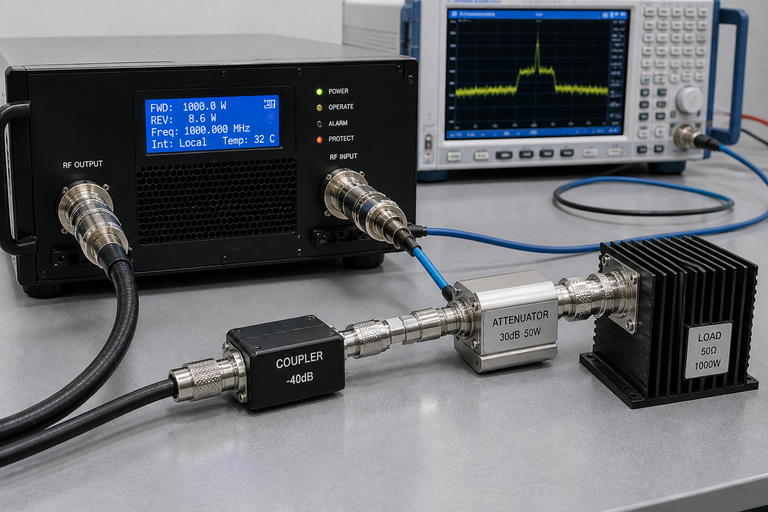
EMC amplifier procurement should not rely only on rated power and brochure wording. CorelixRF can support unit-level RF validation data before shipment, depending on project requirements.
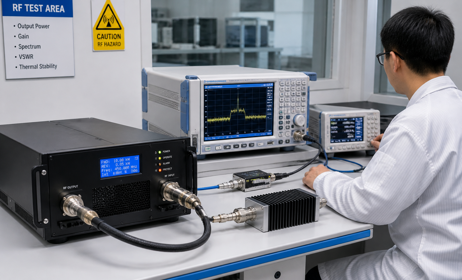 Output power / gain / spectrum validation
Confirm that the amplifier platform can support the required output level across the target frequency window, not only at a single point.
Review gain behavior across the required band to support system-level planning and test repeatability.
Check spectrum-related performance based on the test platform and project documentation requirements.
Review cooling, temperature behavior and thermal margin for long-duration or high-power EMC test operation.
Review mismatch conditions, reflected power risk and protection behavior when antennas, chambers or fixtures are involved.
Support inspection records, labeling, packing confirmation and project documentation before shipment where applicable.
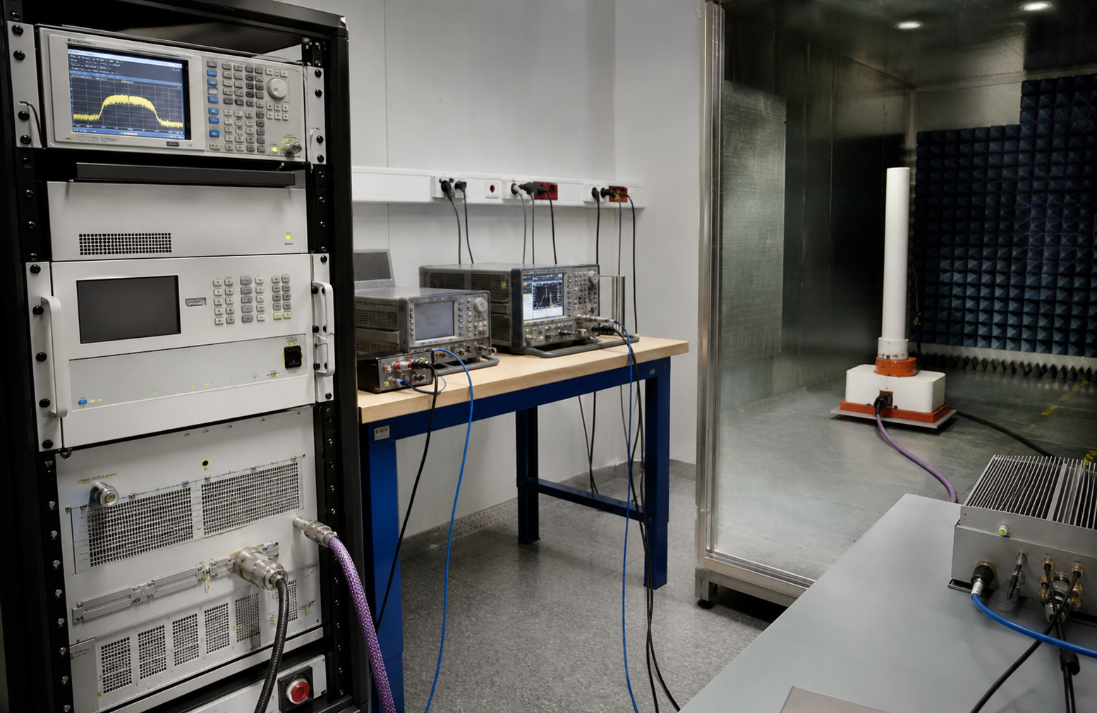
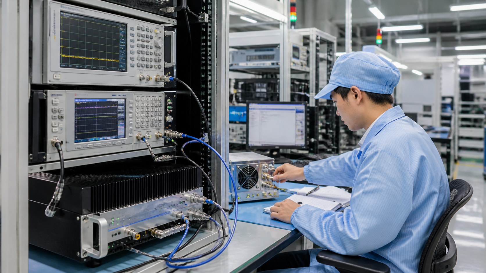 Factory RF testing and validation
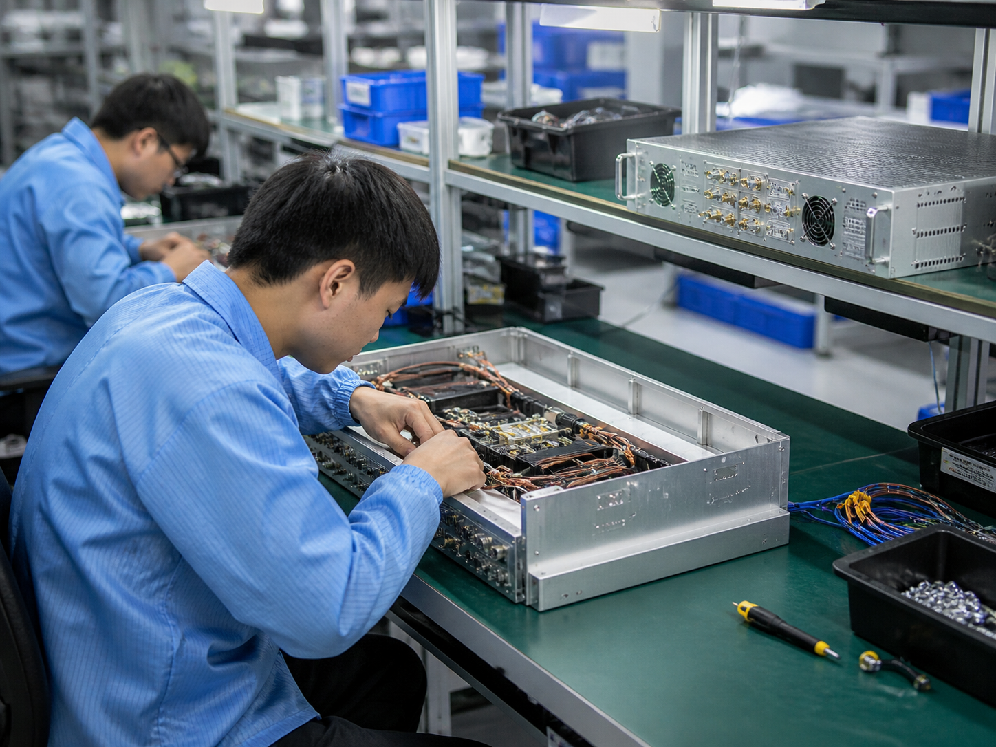
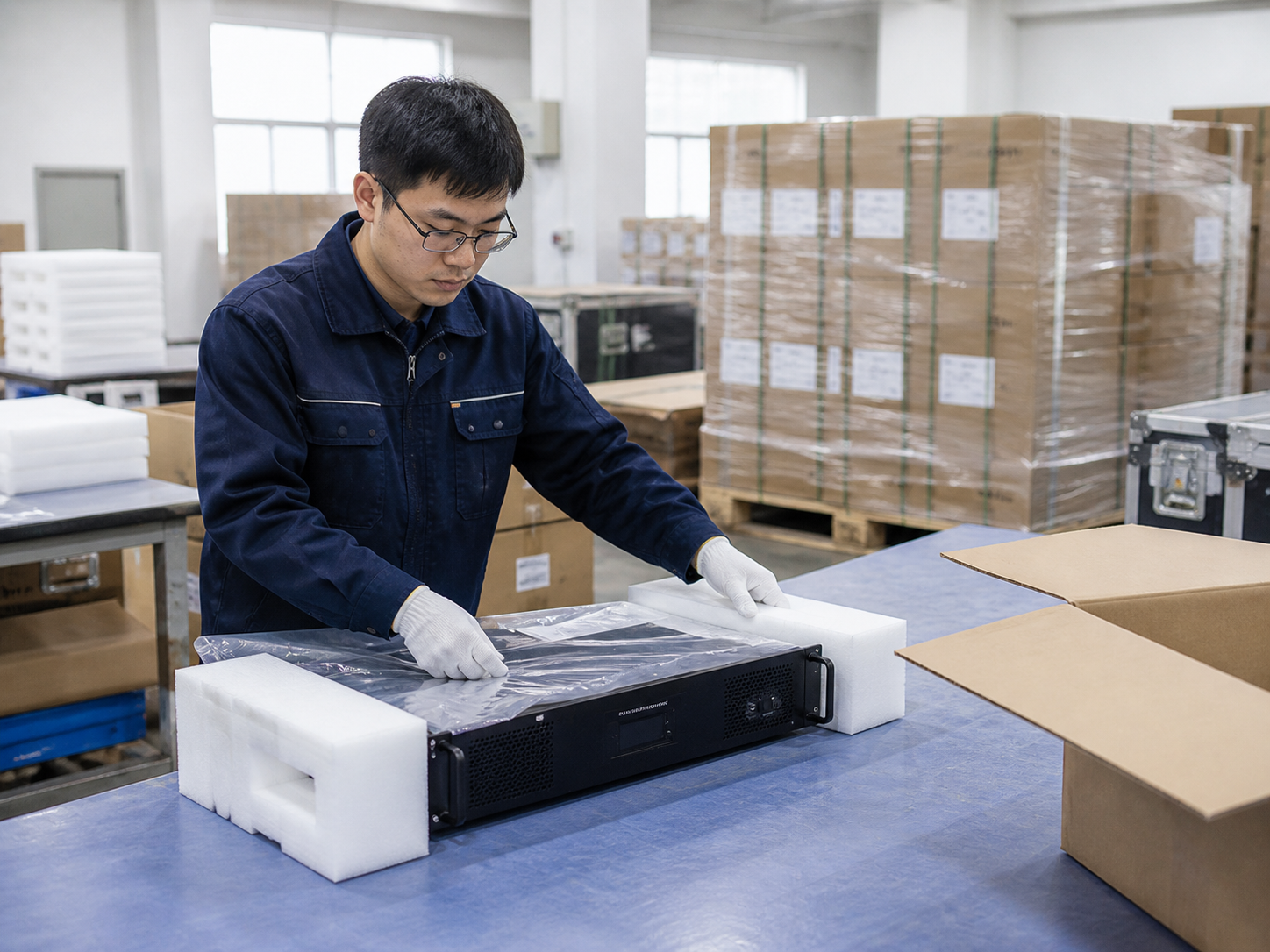
CorelixRF supports EMC amplifier projects through in-house RF engineering, controlled production, module and rack-level integration, RF testing and project-based customization.
Frequency, power, control, protection and mechanical requirements can be reviewed by an RF engineering team.
Packing, labels, inspection records and project documentation can be coordinated before export delivery.
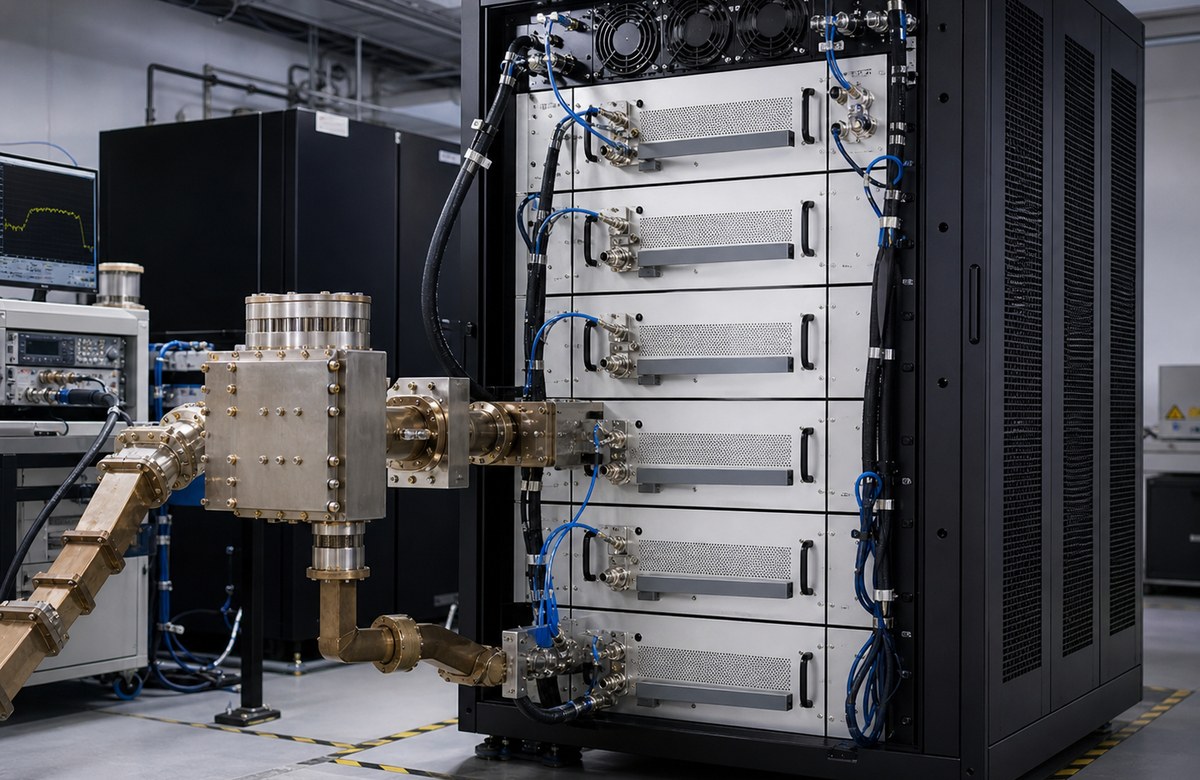
Support for rack-mounted platforms, OEM/ODM integration and project-specific mechanical requirements.
Output power, gain, spectrum and thermal behavior can be reviewed before delivery based on project needs.
A reliable EMC amplifier platform should be selected by operating conditions, integration needs and validation evidence, not by rated power alone.
Rated power does not always mean full-band output power. Ask for performance across the required frequency window.
VSWR and mismatch behavior should be reviewed when antennas, chambers or fixtures are involved.
High-power and long-duration EMC testing requires thermal review, airflow planning and protection behavior.
Pulse width, duty cycle and timing behavior can change the correct amplifier configuration.
Output, gain, spectrum and thermal data can reduce procurement risk before integration.
Remote control, monitoring, safety interlock, connector type and system communication requirements should be confirmed early.
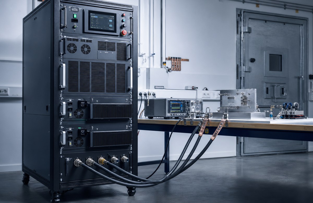
EMC amplifier platforms are used in controlled RF test environments where power stability, protection, documentation and integration reliability matter.
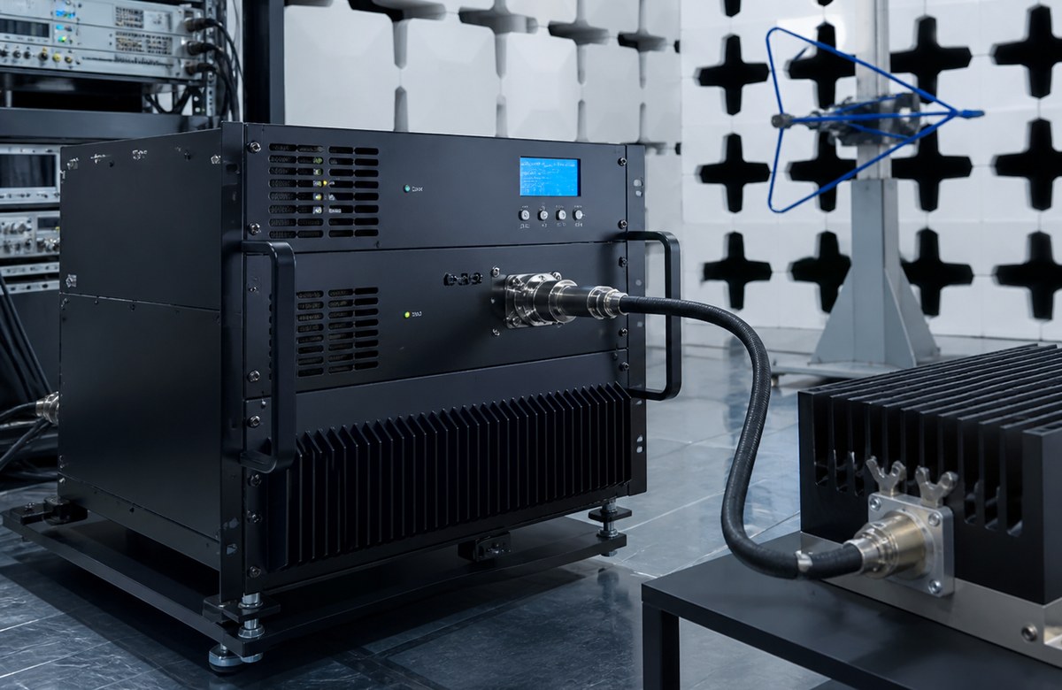
Amplifier platforms for controlled high-power RF output in EMC-related immunity test environments.
Low-frequency and UHF amplifier platforms for conducted RF testing and system validation.
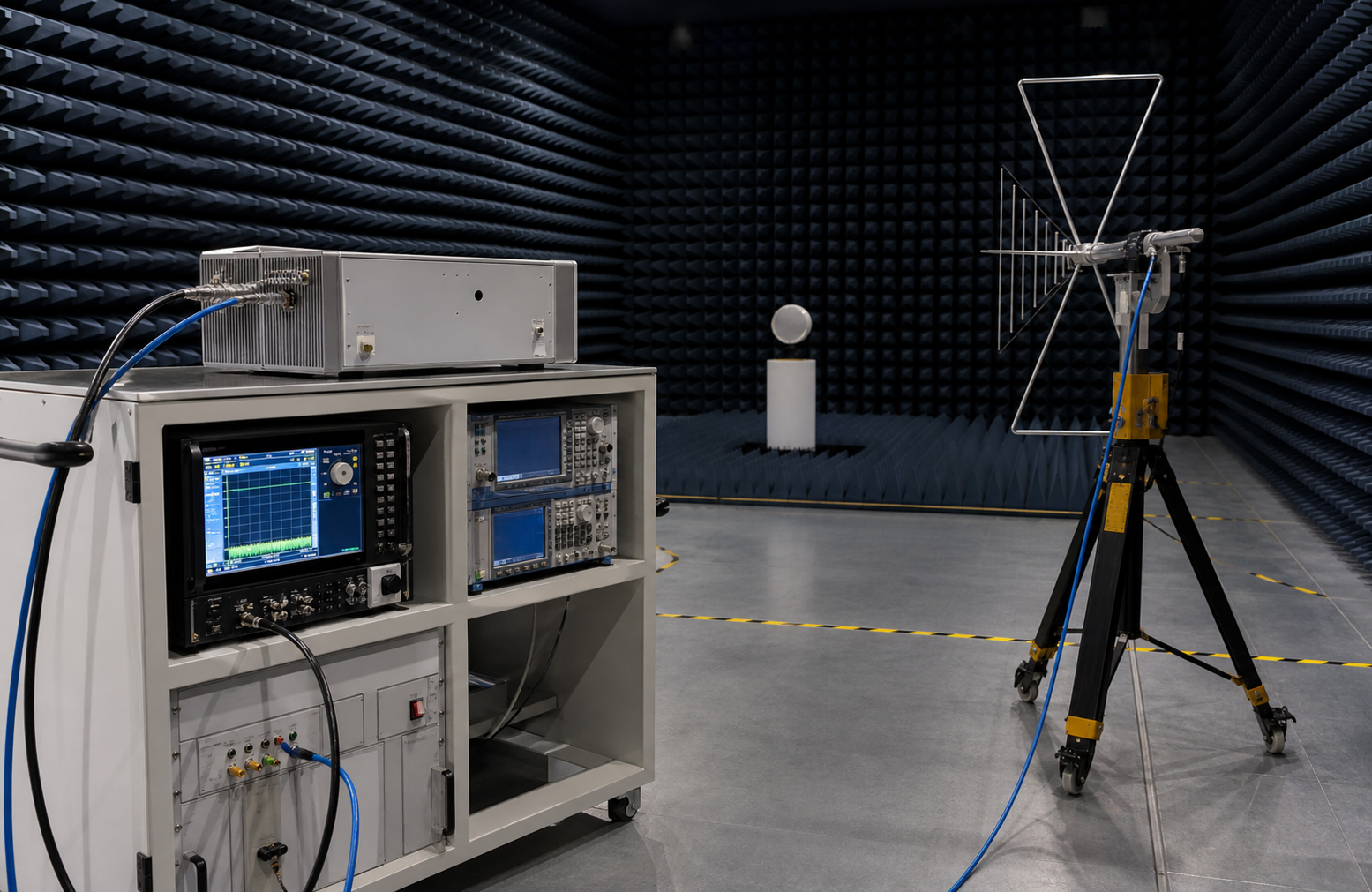
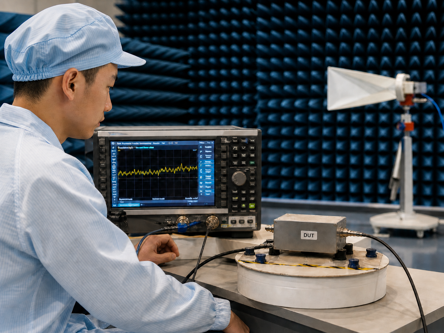
Power amplifier support for RF test setups involving antennas, chambers and radiated field environments.
Amplifier platforms for RF component, antenna, subsystem and test bench validation programs.
An EMC RF amplifier provides controlled RF power for EMC-related test environments, including immunity testing, conducted RF testing, radiated RF test setups, laboratory RF validation and compliance-related amplifier systems.
CorelixRF supports EMC amplifier platform areas from kHz-range low-frequency systems to UHF, broadband GHz and microwave amplifier platforms, including project-based custom platforms up to extended high-frequency ranges.
Yes. Output power can be reviewed based on frequency range, required margin, CW or pulse operation, duty cycle, load environment, cooling condition and mechanical integration requirements.
CorelixRF can review CW or pulse requirements depending on the amplifier platform. Pulse width, duty cycle, timing behavior and thermal margin should be confirmed before final recommendation.
Depending on project requirements, measured RF data can include output power, gain flatness, harmonics, spurious performance, thermal behavior and unit-level inspection records.
Please provide frequency range, target output power, CW or pulse operation, load or chamber condition, duty cycle, cooling space, connector type, control interface and required test data or documentation.
Yes. CorelixRF supports OEM/ODM integration review and NDA-based discussions for project-specific RF amplifier platforms, mechanical structures, control interfaces and system integration needs.
Send your frequency range, required output power, CW or pulse condition, load or chamber environment, cooling requirement, RF connector, control interface and documentation needs. CorelixRF will review whether a standard platform or custom configuration is more suitable.
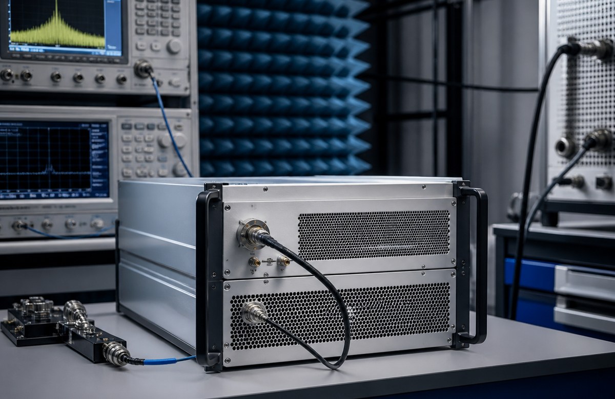
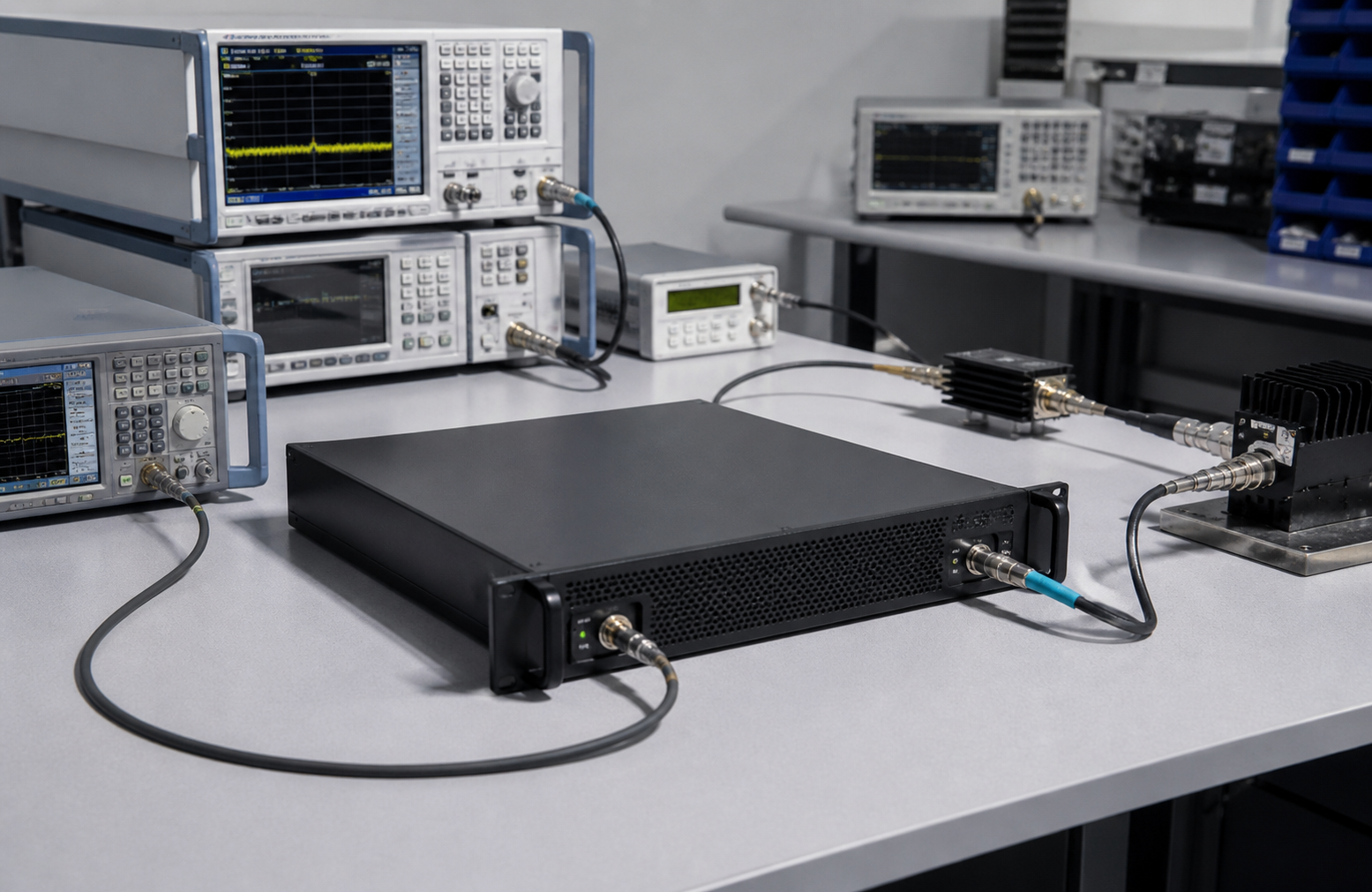
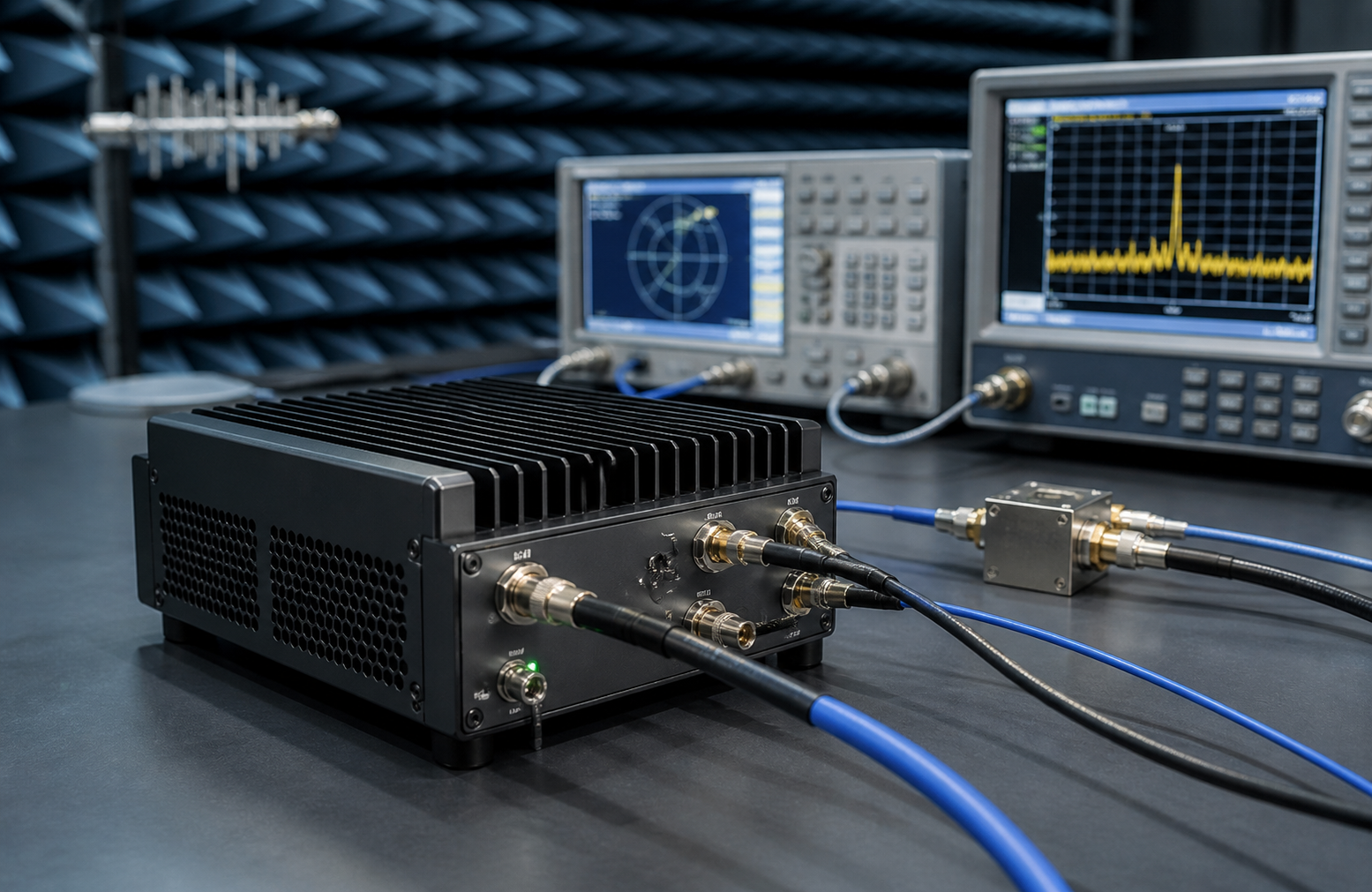
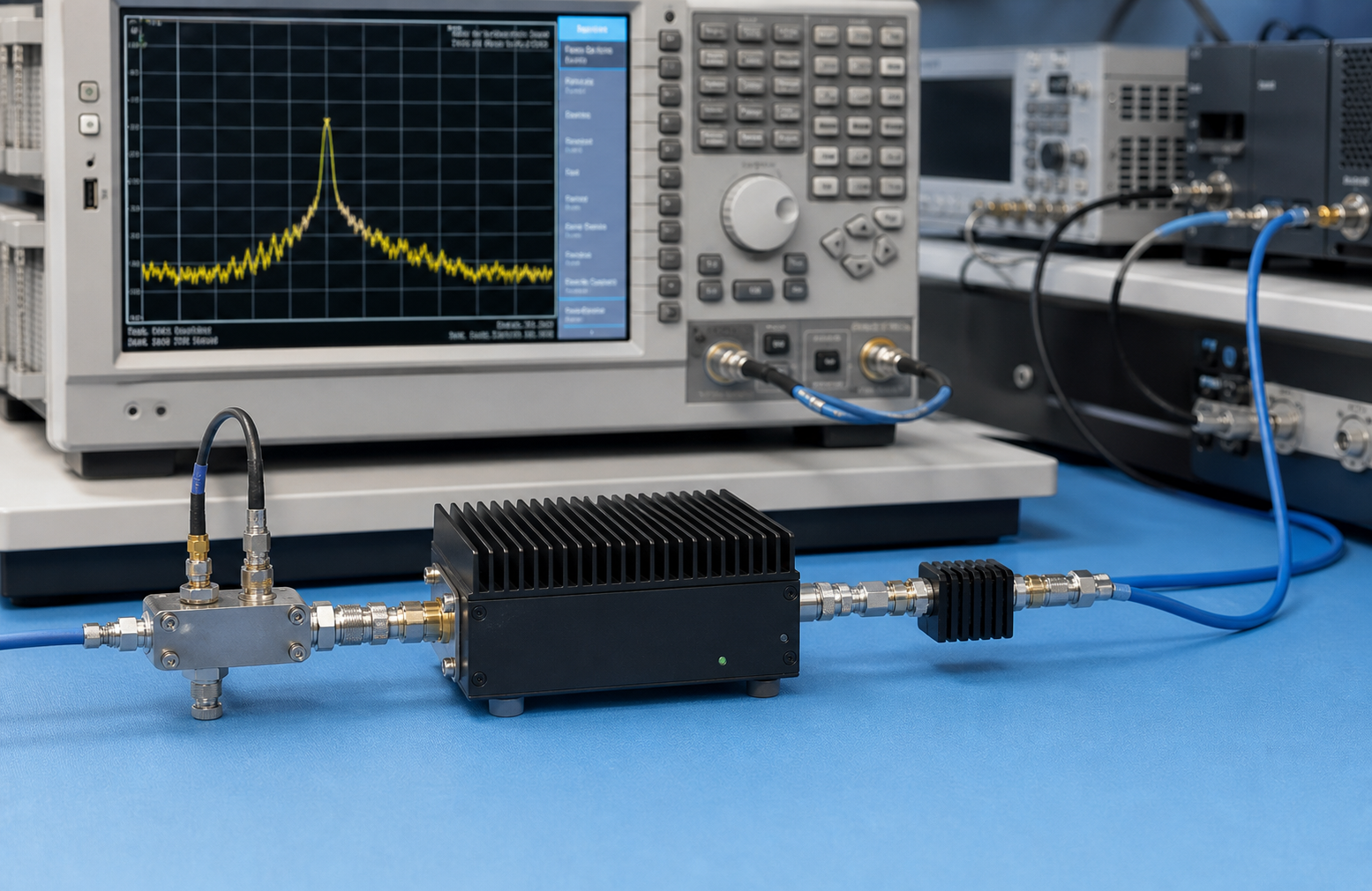
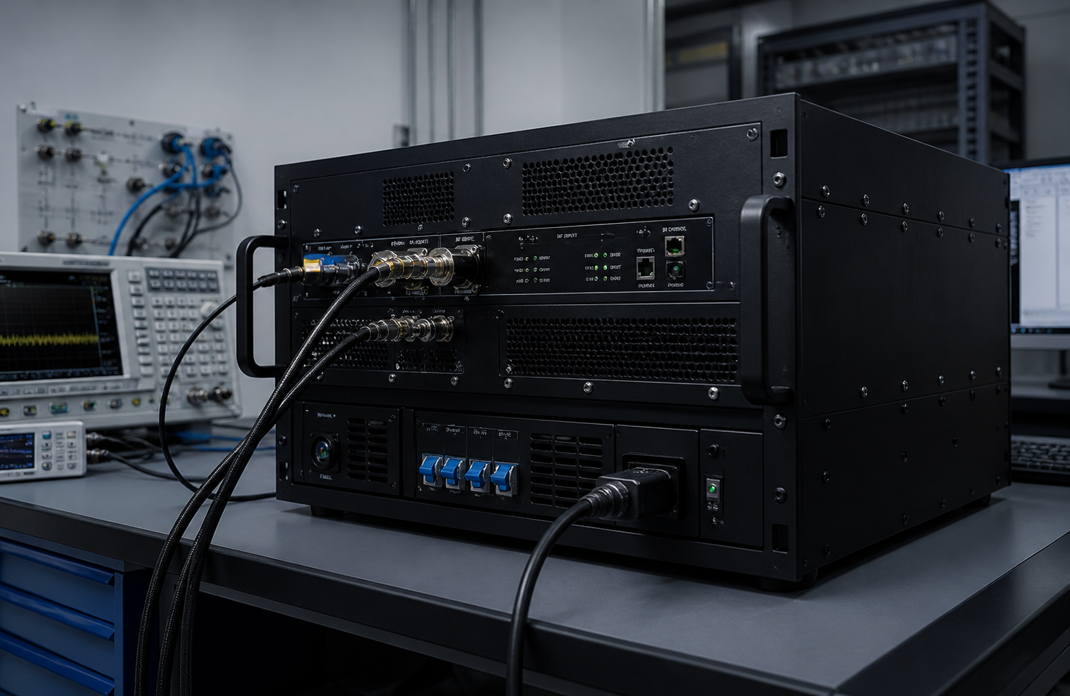
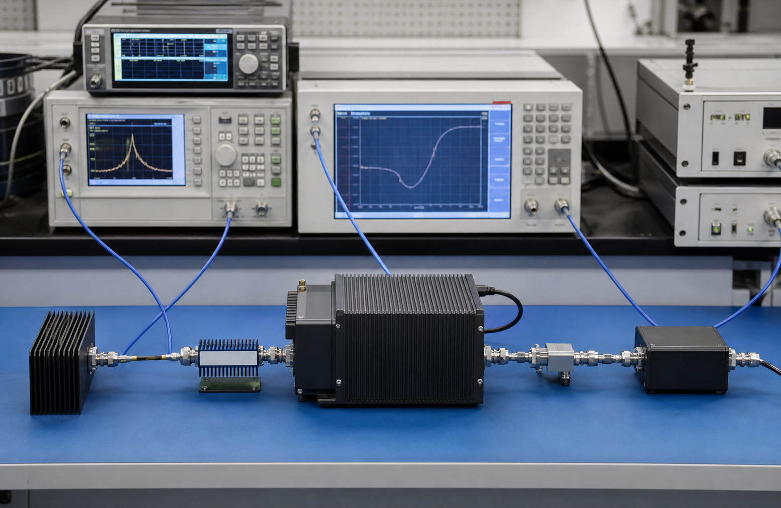
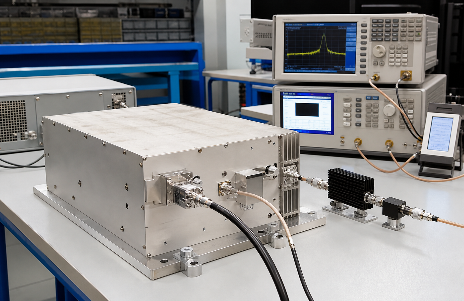
 RF connector / test chain close-up
EMC AMPLIFIER PROCUREMENT EVIDENCE
EMC amplifier projects need more than a headline wattage number. Buyers should align frequency band, field-strength target, antenna path, dwell time, protection behavior, cooling and calibration-related documentation before quotation.
Map immunity test bands, chamber setup and antenna path to the amplifier platform.
Read EMC selection guideConfirm whether standard RF power amplifier platforms or modified builds fit the lab requirement.
RF amplifier platformsAsk for test records, delivery documentation and acceptance notes before final approval.
Delivery documentation