CorelixRF | RF Systems Solutions
Custom SDR Signal Source Manufacturer | Factory-Direct OEM SDR 100 MHz–6 GHz | CorelixRF
CorelixRF // Factory-Direct SDR Manufacturer

Custom SDR Signal SourceManufacturer for OEM RF Projects

Factory-direct custom SDR development for frequency planning, waveform customization, interface adaptation, and prototype-to-batch RF integration. 100 MHz–6 GHz dual-channel architecture.

Not an off-the-shelf module — factory-backed custom development platform
100 MHz–6 GHz Dual Channel RS422 / Custom Interface Waveform Customization OEM / ODM Support
Frequency Range
100 MHz6 GHz
Max Bandwidth / Channel
100 MHz
Channel Architecture
2 Independent
Project Customization
Waveform / Interface / Mechanical
Custom SDR signal source module for OEM RF integration
CUSTOM SDR // OEM RF MODULE
▸ VERIFIED
Factory-Direct Manufacturer
▸ MOQ
Prototype MOQ 1 Unit
▸ PLATFORM
100 MHz–6 GHz Mature SDR Platform
▸ SUPPORT
RF / Firmware / Integration Engineering
▸ SUPPLY
Prototype to Batch Production
▸ CERTIFIED
ISO 9001 / GJB 9001C
Who This Custom SDR Page Is For

Not a Standard Product Page.
A Factory-Backed Customization Platform.

01 //Who We Serve

Custom SDR projects typically come from integrators, OEM developers, and technical teams that require platform-level RF adaptation rather than off-the-shelf modules.

  • Counter-UAS system integrators
  • RF system OEM developers
  • Defense electronics engineering teams
  • Lab and validation teams needing custom signal generation
  • Platform builders requiring control interface adaptation
  • Buyers needing prototype-to-batch supply continuity

02 //What Can Be Customized for Your Project

Customization is applied across RF planning, waveform logic, interface mapping, and mechanical integration — each aligned to your actual project requirements.

  • Frequency plan and band allocationTo match your target operating band instead of using a generic full-band module
  • Waveform behavior and signal logicTo fit your deployment logic, modulation strategy, or test objective
  • Control interface adaptationTo match your existing host-side command architecture without redesign
  • Mechanical and connector integrationTo reduce redesign work on your side during system integration
  • Prototype-to-batch production versionsSame BOM, same firmware — consistent supply from first unit to volume
Why Buyers Come to Us

Problems We Help Solve

FREQUENCY
Need non-standard frequency coverage for your project?
We define project-specific band allocation instead of forcing you into a generic full-band platform.
OUTPUT
Need dual-channel coordinated or independent output?
Channel synchronization behavior is configurable — synchronized sweep or fully independent operation per project requirement.
INTERFACE
Need RS422 or a project-specific control protocol?
We map the command set to your host architecture — RS422 standard, or UART / SPI / Ethernet / custom protocol on request.
WAVEFORM
Need custom waveform logic or deployment behavior?
Modulation presets, IQ file loading, and custom signal behavior can all be adapted. NDA-protected development available.
SOURCE
Need a real source factory, not a trading company?
In-house SMT, RF test lab, and firmware team — every unit built, flashed, and tested on our own factory floor.
CONTINUITY
Need prototype-to-batch continuity and repeated supply?
Once configuration is locked, BOM and process are frozen — consistent supply from prototype through multi-year volume programs.
SDR Customization Scope

Define Your Configuration

Typical SDR customization scope includes frequency planning, waveform logic, and control interface adaptation. Select across 3 axes below — preview updates live.

01
Frequency Planning
Operating band and channel allocation
Full Range100M–6G
UHF Band100–512M
Sub-3 GHz700M–2.7G
ISM Dual Band2.4G+5.8G
Custom PlanRFQ
02
Waveform Customization
Signal behavior and modulation type
OFDM SweepBROADBAND
LFM ChirpCHIRP
Protocol-TargetedADAPTIVE
CW CarrierSINGLE TONE
Custom IQ FileNDA OK
03
Interface Integration
Host system control method
RS422STANDARD
UARTCUSTOM
EthernetCUSTOM
SPI / GPIOCUSTOM
Custom ProtocolRFQ
RECOMMENDED CUSTOM SDR DIRECTION
Frequency Plan
Full 100 MHz – 6 GHz
Waveform
OFDM (5–100 MHz BW)
Control Interface
RS422 (Standard)
Channels
2 × Independent
BW per Channel
Up to 100 MHz
Integration Note
Suitable for platform-level OEM control
Mechanical / Connector Adaptation
Board-level adaptation, enclosure dimensions, connector layout, and thermal coordination for your system integration requirements.
Firmware / Command Set Coordination
Command set customization, host-side integration support, and deployment logic adaptation to match your control architecture.
Base Platform Architecture

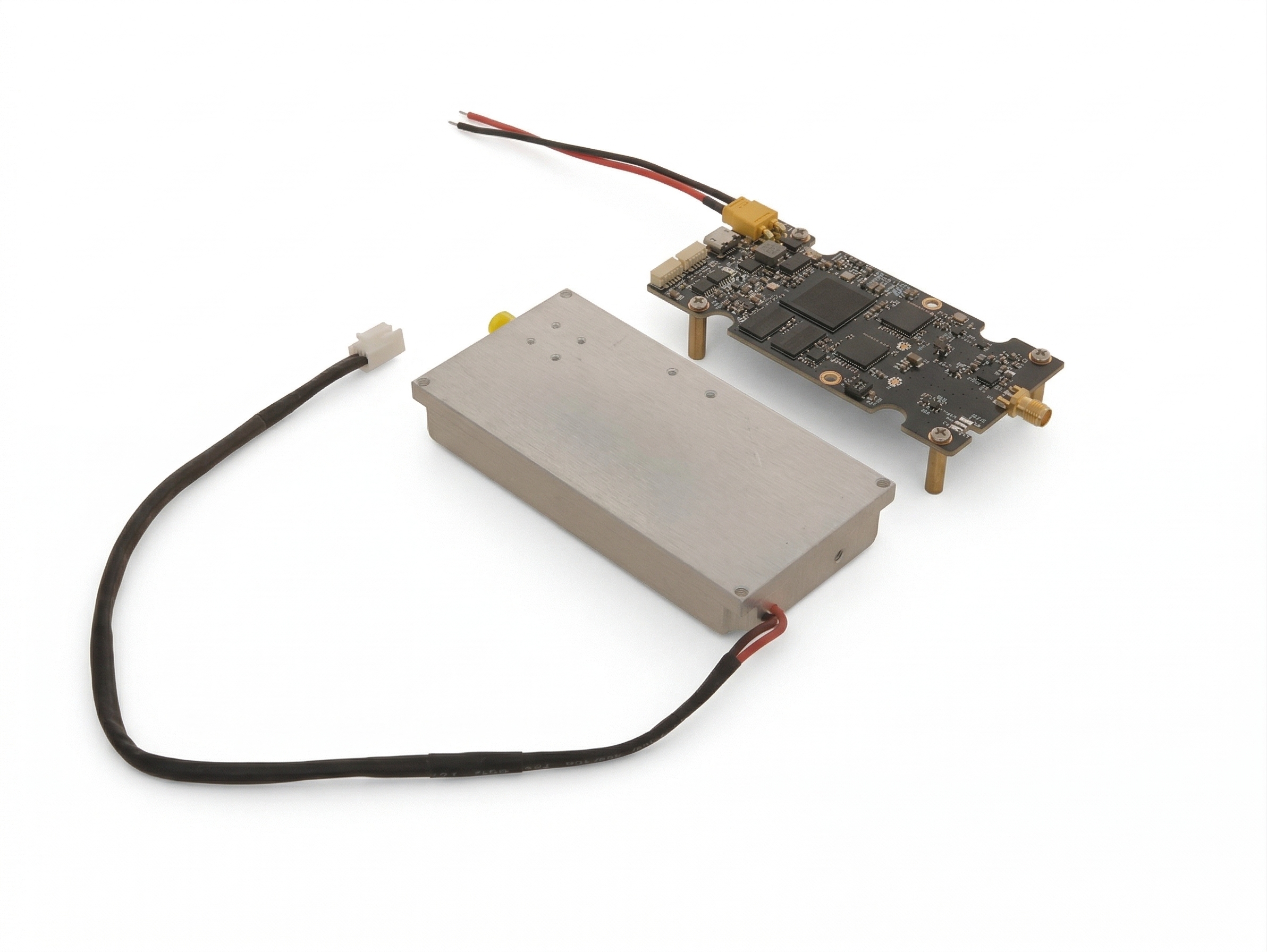
Custom Development Built on
a Proven SDR Platform

RF CORE
Frequency Range 100 MHz – 6,000 MHz
Output BW / Channel Up to 100 MHz
Channel Count 2 × Independent
Centre Freq Accuracy ±1 Hz programmable
Spurious Suppression > 60 dBc typical
INTERFACE
Standard Control RS422
Custom Options UART / SPI / Ethernet / GPIO
RF Outputs 2 × SMA female
Multi-module Cascade Via RS422 daisy-chain
ENVIRONMENTAL
Operating Temp −40°C to +85°C
Environmental Testing Available based on project scope
Burn-in Available at rated power
SUPPLY
MOQ 1 unit
Typical Prototype Lead Time ~7 business days
Certifications ISO 9001 · GJB 9001C

All customization is built on this proven SDR platform — ensuring project stability while enabling full flexibility across frequency, waveform, interface, and mechanical dimensions.

WHAT STAYS STANDARD VS WHAT CAN BE CUSTOMIZED
STANDARD
Core RF architecture · Dual-channel base platform · Platform firmware foundation · Core environmental design
CUSTOMIZABLE
Frequency plan · Signal logic / waveform behavior · Control interface · Connector layout · Mechanical enclosure · Command set mapping

AVAILABLE ON REQUEST: DATASHEET, COMMAND SET, INTERFACE GUIDE, AND SAMPLE TEST REPORT.

Project Adaptation Scenarios

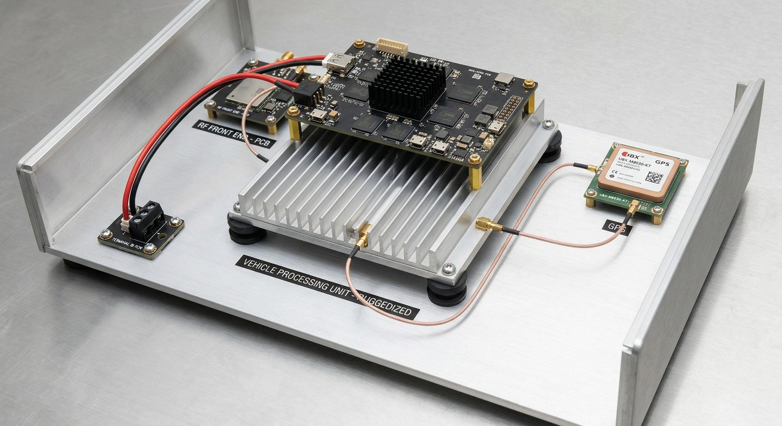
Where Custom SDR Platforms Are Deployed

Counter-UAS SDR platform with custom frequency planning and RS422 host control
01
Counter-UAS System Integration
Custom frequency planning and host-side interface adaptation align the SDR platform with multi-band C-UAS architectures. Reduces integration friction versus generic full-band modules.
MULTI-BANDRS422 C2OEM
RF signal simulation laboratory with custom waveform SDR setup
02
RF Signal Simulation & Testing
Custom waveform files and bench-friendly interfaces reduce lab setup complexity. IQ playback and modulation adaptation tailored to your test objectives.
IQ PLAYBACKCUSTOM WFLAB
Vehicle-mounted RF platform with ruggedized SDR integration
03
Vehicle-Mounted RF Platforms
Mechanical layout, vibration coordination, and control interface adaptation reduce vehicle integration effort. Ruggedized configurations available for field deployment.
MOBILERUGGEDFIELD
Fixed-site RF deployment system with custom frequency SDR
04
Fixed-Site Deployment Systems
Custom frequency plans optimize band coverage for permanent installations. Multi-module cascade via RS422 daisy-chain for extended system architectures.
FIXEDCASCADEFULL BAND
Special-purpose RF electronic system development with NDA support
05
Special-Purpose RF Development
Dedicated engineering coordination and custom waveform development for classified or NDA-protected projects. Protected requirement handling from first contact.
CUSTOM WFNDA OKPROTECTED
Laboratory and engineering validation setup with custom SDR prototype
06
Laboratory & Engineering Validation
Quick-turn prototype configurations and engineering-grade documentation support system verification. MOQ 1 unit — no volume commitment needed to start validation.
BENCHMOQ 1PROTOTYPE
Custom vs Standard

Why Custom Development Instead of Standard Modules

Standard off-the-shelf SDR modules solve general problems. These four scenarios are where custom development delivers measurably better project outcomes.

01
Standard models may not match your project interface requirements
Fixed interfaces require additional adapters or redesign on the host side. A matched control interface eliminates this friction entirely.
02
Fixed frequency plans increase integration friction
Custom frequency planning aligns the SDR output precisely with your target band — no unused bandwidth, no band gaps to work around.
03
Custom waveform logic improves deployment fit
Signal behavior adapted to your modulation strategy, deployment logic, or test scenario — not constrained by generic preset libraries.
04
Factory engineering support shortens validation cycles
Direct access to the RF and firmware team that designed the platform. Faster issue resolution, shorter time from prototype to production.
Project Readiness Guide

Before Starting a Custom SDR Project

Confirm these points before initiating a custom SDR development — early clarity reduces redesign risk, iteration cycles, and integration delays.

Is the operating band continuous or segmented across multiple sub-bands?
Does the control interface match your host architecture — or does it need adaptation?
Do you need synchronized or fully independent channel behavior?
Is the module intended for bench use only, or field deployment with environmental requirements?
Will you require test reports, integration documents, and command set guides?
Do you need prototype-to-batch BOM continuity for long-term supply assurance?
Is the supplier a verified manufacturer — with in-house SMT, RF test, and firmware development?
Can the supplier support repeated orders under a locked configuration across project cycles?
Engineering Process

From Requirement to
Volume Production

Six structured stages — each with a defined output your team receives before the next stage begins.

01
STEP 01
Requirement Review
Submit frequency, interface, waveform, environment, and quantity targets. Engineer-direct communication. NDA issued on request for protected projects.
02
STEP 02
Technical Evaluation
RF and DSP team reviews feasibility against platform architecture. Written evaluation and customization proposal typically delivered within 48 hours.
03
STEP 03
Architecture Confirmation
Component BOM locked. Custom waveform files validated. Firmware configuration finalized. You receive a confirmed spec and project timeline before build begins.
04
STEP 04
Prototype Development
In-house SMT, firmware load, full RF sweep. Prototype built on the mature SDR platform with function validation before delivery. Typical lead time ~7 business days.
05
STEP 05
Testing & Validation
Environmental testing available based on project scope — burn-in, thermal cycling, vibration screening. Per-unit test report provided with each prototype delivery.
06
STEP 06
Batch Production & Delivery
Locked configuration, consistent BOM, and repeatable production for long-term supply. Integration support and documentation included through deployment.
Factory Capability Behind
Custom SDR Projects
0+
Years RF Manufacturing
0+
In-House Engineers
10K
Monthly Capacity Available
In-House SMT
Full SMT line with AOI and X-ray — every board built on our factory floor. Better schedule control for prototype build and repeated batch production.
RF Test Lab
Calibrated benches for full 100 MHz–6 GHz sweep, power measurement, and signal quality. Each custom configuration validated before shipment — not based on platform-level assumptions.
Environmental QA
Burn-in, thermal cycling, and vibration screening available based on project scope. Test data retained per unit — you receive traceable QA records, not just pass/fail summaries.
Firmware Team
DSP and embedded engineers write every line of baseband firmware in-house. Command logic and waveform behavior adapted without depending on third-party development cycles.
Project Risk Control

Project Risk Control & Supply Assurance

Factory-direct engagement means fewer handoff points, faster resolution, and a supply chain you can plan around.

0+
Countries Served
Asia, Europe, Middle East, Latin America
0+
Projects Delivered
Prototype, small batch, and volume programs
1 BD
Technical Response
Initial engineering review for most inquiries
Multi-Year
Customer Programs
Repeat orders with consistent BOM continuity
Locked Config Supply
Batch Repeatability
Same BOM, same process, same quality from first unit through multi-year volume programs
Source Factory Communication
Direct contact with the factory team — no intermediaries, no requirement loss between your team and ours.
Engineering-Backed Requirement Review
Specs reviewed by the team that designed the platform — improving requirement matching and reducing iteration cycles.
Prototype-to-Volume Continuity
Same BOM and process from prototype through volume. Long-term supply agreements available for repeat programs.
Export Project Coordination
International delivery experience across Asia, Europe, and Middle East. Documentation, packaging, and logistics aligned to overseas requirements.
Faster Technical Response
Talk directly to RF engineers who understand your application. No handoff delay between sales and technical teams.
Production & Documentation Support
Scheduling, testing, and shipment managed under one roof. Test reports, command set guides, and integration documentation included.
Inside the Factory

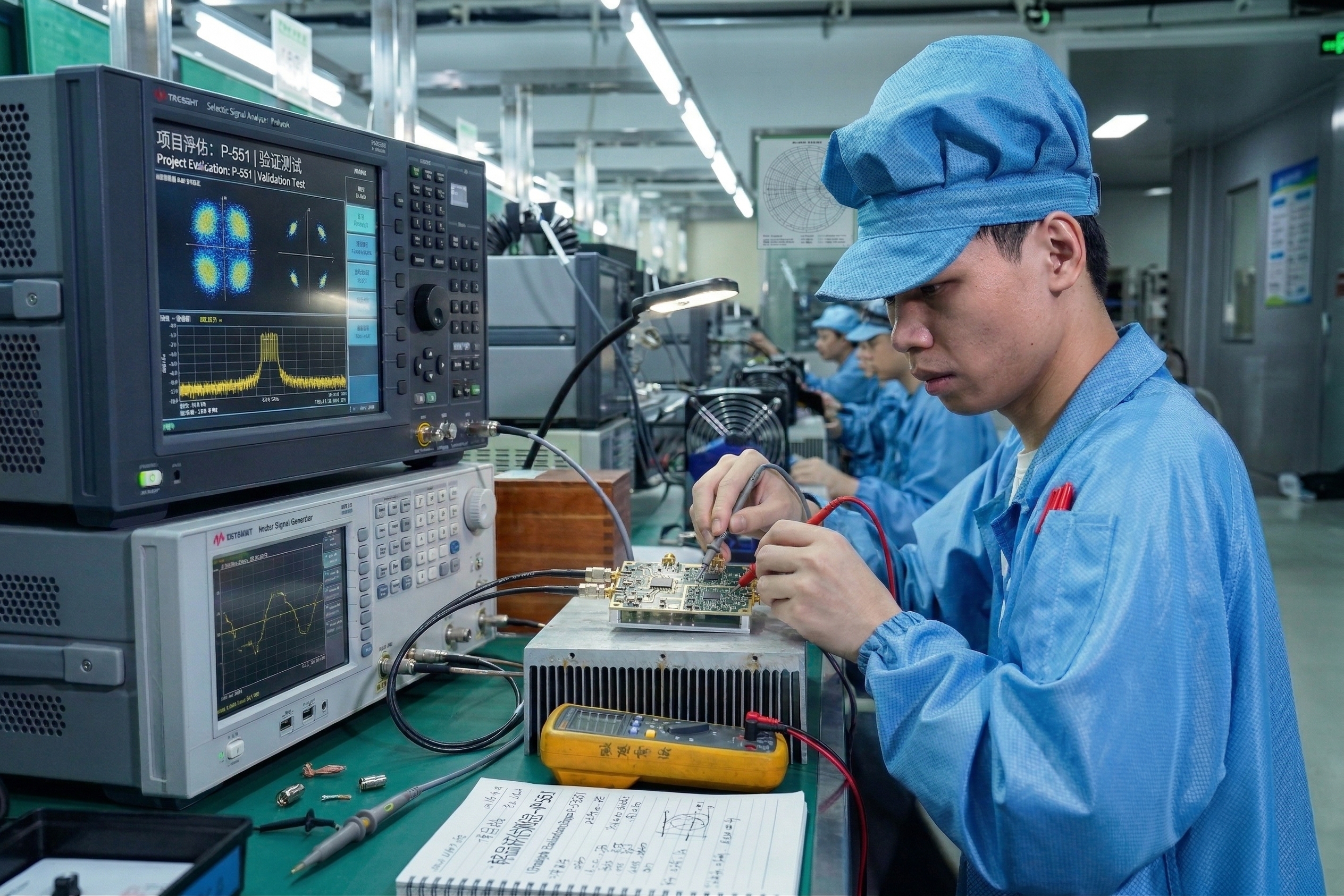
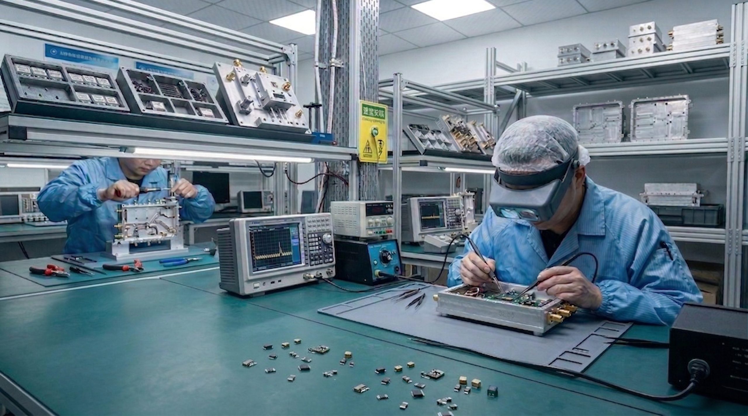
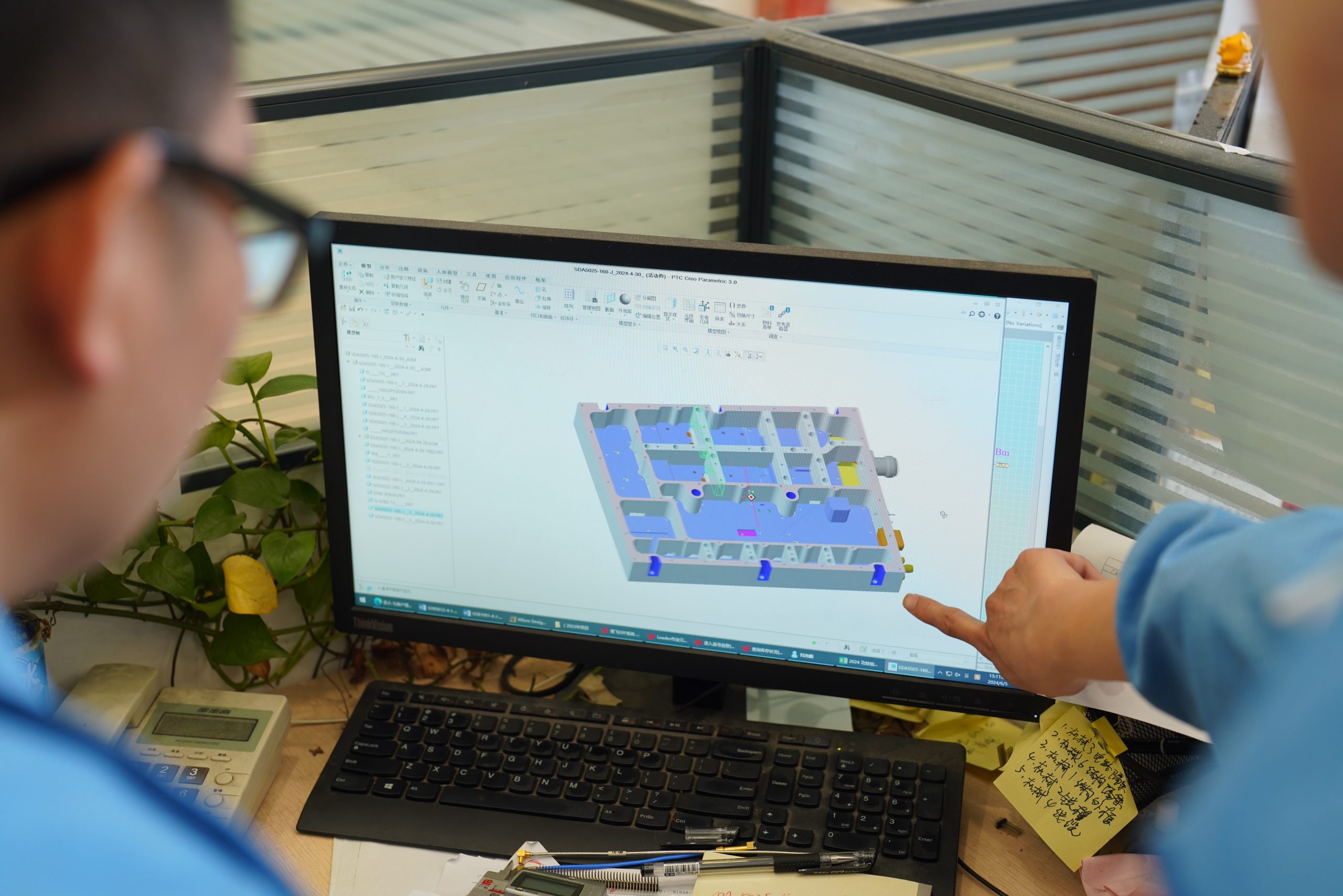
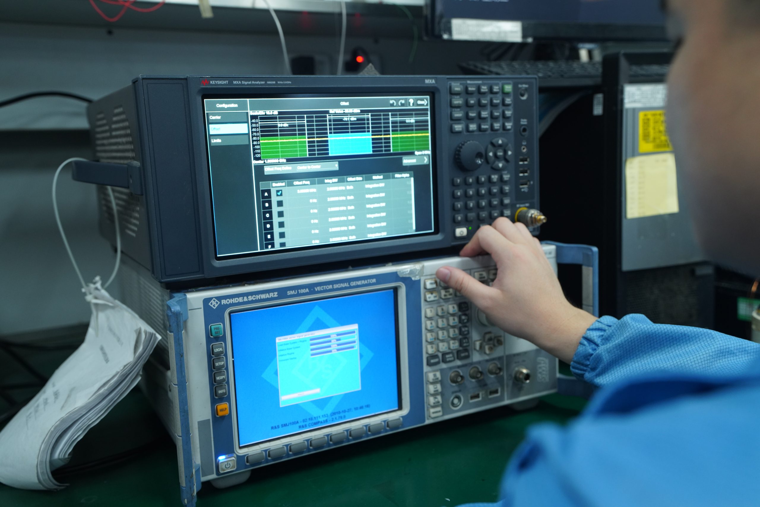
See How It's Built and Shipped

Real production, testing, and delivery operations — not stock footage.

SDR module production floor video
Production Floor
SMT line, AOI, X-ray inspection
RF test bench calibration video
RF Testing
Full sweep, power measurement, QA
Burn-in and environmental testing video
Burn-in & Inspection
Thermal cycling, vibration, stress test
Product packing and shipment video
Packing & Shipment
ESD protection, export packaging
Certifications & Compliance

Quality Systems & Compliance Support

ISO 9001
GJB 9001C
CE
RoHS
FACTORY QMS
ISO 9001 and GJB 9001C apply to our factory quality management system — covering production, inspection, and traceability processes.
PRODUCT COMPLIANCE
CE and RoHS compliance available for export programs. Applicable scope depends on project configuration and destination market requirements.
ON REQUEST
Certificate copies, test reports, and compliance documentation available on request for procurement review and overseas import requirements.
Frequently Asked Questions

FAQ

Can you customize the frequency range and channel setup?

Yes. We support custom frequency plans within the 100 MHz to 6 GHz range, including sub-band definition, channel planning, and project-specific band allocation. Dual-channel output can be configured as synchronized or independent.

Do you support custom control protocols?

RS422 is the standard interface. We also support UART, SPI, Ethernet, GPIO, and fully custom communication protocol mapping based on your host system requirements.

Can waveform behavior be modified?

Yes. We support custom waveform presets, modulation adaptation, project-specific signal behavior, and IQ file loading (.sc16 format). NDA-protected custom waveform development is available.

What is the usual custom development process?

The process follows six stages: Requirement Review, Technical Evaluation, Architecture Confirmation, Prototype Development, Testing and Validation, and Batch Production. Typical prototype lead time is around 7 business days.

Do you support prototype quantities?

Yes. MOQ is 1 unit. We support single-unit prototypes through to volume production, with full lot traceability and consistent quality.

Can you provide integration documents and test support?

Yes. We provide full datasheets, RS422 integration guides, command set documentation, test reports (redacted samples available), and on-call RF engineering support during integration.

Which industries typically use this SDR platform?

Counter-UAS integration, RF signal simulation, vehicle-mounted RF systems, fixed-site deployment platforms, laboratory and engineering validation, and special-purpose RF development projects.

Can you support long-term repeated supply?

Yes. Once a custom configuration is locked, we maintain BOM consistency and production process continuity for repeat orders. Long-term supply agreements are supported.

Before You Inquire

Information That Helps Us Review Your Project Faster

Typical Customization Requests
  • Need sub-band locking instead of full-range operation?
  • Need synchronized dual-channel output for coordinated transmission?
  • Need Ethernet or SPI instead of RS422 control?
  • Need custom IQ file loading behavior or waveform logic?
  • Need board-level or connector layout adaptation?
  • Need field-deployment rather than lab-only configuration?
Information We Need for RFQ Review
  • Target frequency range or sub-band plan
  • Required channel count and synchronization behavior
  • Bandwidth per channel
  • Preferred control interface (RS422, UART, Ethernet, SPI, etc.)
  • Waveform or signal type requirements
  • Mechanical constraints or enclosure requirements
  • Prototype quantity and expected batch volume
Start Your Custom SDR Project

Send Your SDR
Project Requirements

Share your target frequency range, waveform logic, interface, deployment environment, and prototype quantity. Our engineering team will review feasibility and propose a suitable customization path.

Upload Specification / Requirement File
PDF · Word · Excel · Image · Block Diagram  —  Max 10 MB per file, multiple files accepted
1
Unit Minimum
~7d
Typical Prototype Lead
10K
Monthly Capacity