
2–6 GHz RF Power
Amplifiers
Factory-Direct Broadband Modules for RF Testing, Communications & System Integration
Standard 30W to 200W broadband RF power amplifier modules covering 2,000–6,000 MHz, fully documented for engineering review. CorelixRF provides mechanical drawings, performance curves, and customization support — with engineering response within 48 hours.
- Standard 30W / 50W / 100W / 150W / 200W models
- Mechanical drawings & test curves available
- CW / Saturated output formats
- OEM / interface customization supported
- Air-cooled industrial format
- Sample evaluation available
Why Engineers and Procurement Teams Choose CorelixRF for This Series
Four reasons this series reduces technical risk and accelerates project timelines — from initial evaluation through production commitment.
Factory-Direct Manufacturing
No intermediaries. Direct communication with the engineering team that builds and tests every unit. Quotation, customization, and validation are handled by the same team that makes the product.
Standard + Custom Both Supported
The 30W–200W catalog covers most common requirements. When your project needs a specific sub-band, connector type, or control interface adjustment, engineering feasibility review is available without committing to a volume order.
Documented RF Testing & QC
Each unit is linked to an RF verification workflow using calibrated laboratory instruments. Unit-level test records and validation documentation are available based on model scope and project requirements — reducing integration risk at your end.
Engineering Review Before You Commit
Send your parameters and get a model recommendation or customization feasibility response within 48 hours. Mechanical drawings and performance curves are available before order confirmation — no NDA barrier for standard review materials.
2–6 GHz Power Amplifier Selection Guide
All models cover 2,000–6,000 MHz and support CW / saturated operation. The 30W unit uses a compact format; 50W–200W share a common larger platform. Use the Best Fit column to identify your starting point, then send your parameters for a direct recommendation.
| Model | Frequency Range | Output Power | Typical Gain | Gain Flatness | Input Drive | Supply Voltage | Dimensions (mm) | Best Fit / Typical Use | Action |
|---|---|---|---|---|---|---|---|---|---|
| CRF-PA-2G6G-30W | 2,000–6,000 MHz | 30 W | 44–46 dB | ≤ 1.8 dB | 0 to 8 dBm | 36–46 VDC | 125 × 59 × 21.5 | Compact bench evaluation; space-constrained integration environments | RFQ |
| CRF-PA-2G6G-50W | 2,000–6,000 MHz | 50 W | 46–48 dB | ≤ 1.8 dB | −1 to 6 dBm | 40–58 VDC | 200 × 158 × 25 | Entry integration projects; standard test platform deployments | RFQ |
| CRF-PA-2G6G-100W | 2,000–6,000 MHz | 100 W | 49–51 dB | ≤ 1.8 dB | −7 to 6 dBm | 41–51 VDC | 200 × 158 × 25 | Balanced standard platform; most common integration starting point | RFQ |
| CRF-PA-2G6G-150W | 2,000–6,000 MHz | 150 W | 51–53 dB | ≤ 1.8 dB | 0 to 8 dBm | 43–58 VDC | 200 × 158 × 25 | Higher output engineering deployment; demanding test environments | RFQ |
| CRF-PA-2G6G-200W | 2,000–6,000 MHz | 200 W | 52–54 dB | ≤ 1.8 dB | 0 to 8 dBm | 44–54 VDC | 200 × 158 × 25 | Maximum standard platform output; high-power system integration | RFQ |
| Need a specific sub-band, connector layout, or control interface? | Discuss Custom → | ||||||||
Published values are typical model-level reference figures. Final selection should be confirmed against target duty cycle, supply range, thermal conditions, and integration constraints.
Send your target frequency, output power, duty cycle, and supply range — engineering will recommend a model or customization path within 48 hours.
Designed for RF Labs, System Integrators, and Program Buyers
This 2–6 GHz amplifier series is built for teams that need practical broadband RF power hardware with clear documentation. It fits RF testing platforms, communication systems, and integration-led development work where stable power, compact packaging, and dimensional reference matter during project review.
RF Testing Platforms
Used in bench validation, signal-chain evaluation, and RF subsystem development where broadband coverage and repeatable test conditions are required. The 30W and 100W models are common starting points for test platform configurations.
Communication Systems
Suitable for communication-related RF projects that need defined gain, controlled power delivery, and reliable interface matching across a broad frequency span. Output power selection depends on link budget and duty cycle requirements.
System Integration Projects
Useful for teams evaluating mechanical fit, interface compatibility, and supply requirements before committing to a final integrated platform design. Mechanical drawings and connector reference are available before order confirmation.
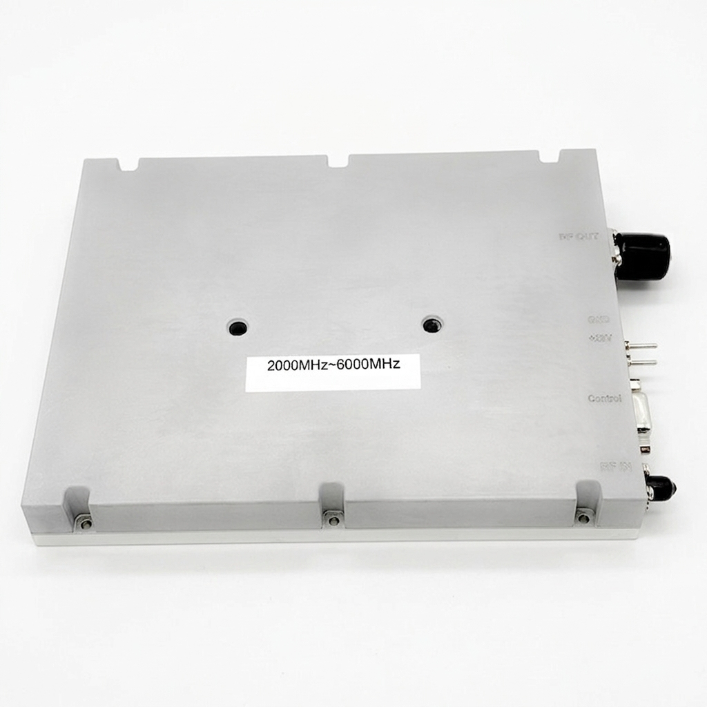
Built Around Broadband Power, Practical Interfaces & Integration Readiness
Broadband 2–6 GHz Coverage
All standard models cover 2,000–6,000 MHz, simplifying model selection for teams working across broad S/C-band-related frequency requirements.
30W to 200W Output Options
The platform spans 30W, 50W, 100W, 150W, and 200W, allowing project teams to choose by output target without switching product families.
Controlled Gain & Flatness
Typical gain ranges from ~45 dB to 53 dB by model. Gain flatness is specified at ≤ 1.8 dB across the entire 2–6 GHz series.
Standard RF & Control Interfaces
SMA at RF input, N-female at RF output, DB9 for control — a consistent interface reference across all power levels. Custom interfaces available.
Air-Cooled Industrial Format
All listed models use air cooling in a clearly documented mechanical envelope, intended for practical hardware deployment and integration review.
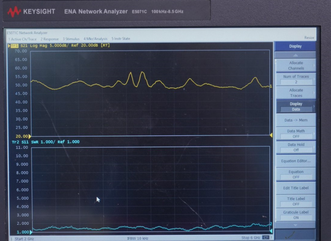
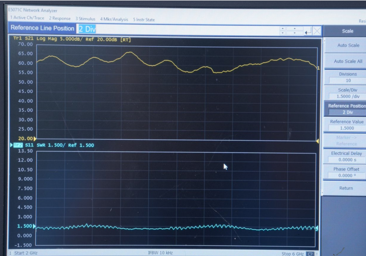
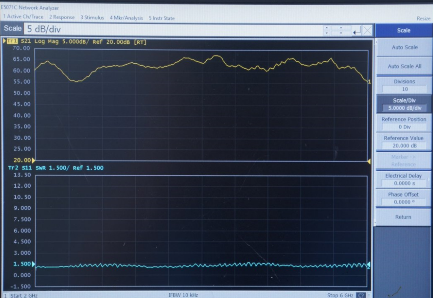
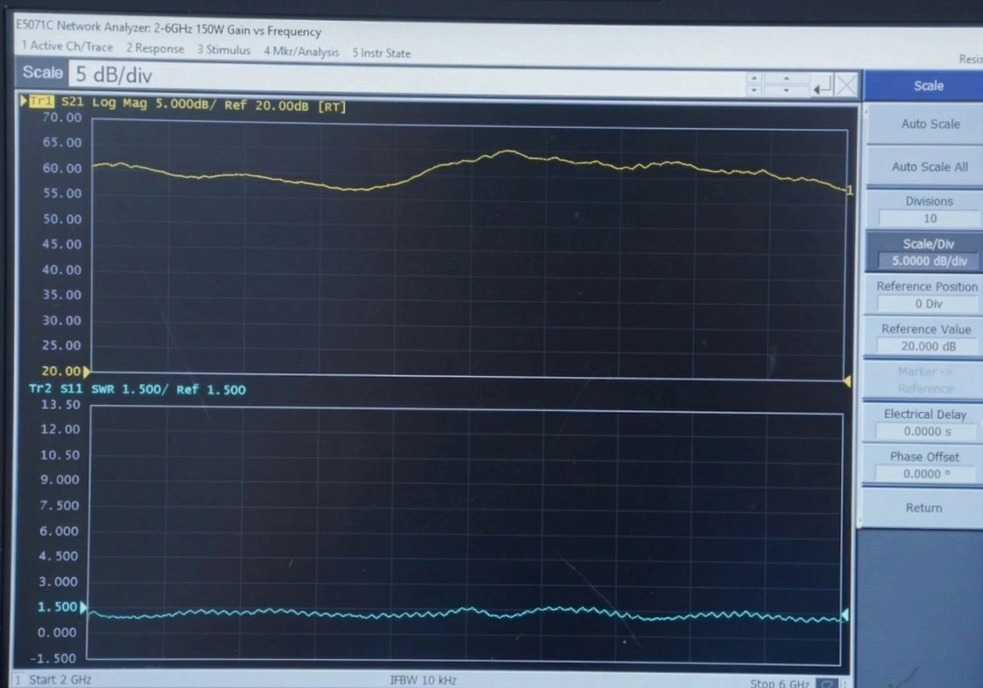
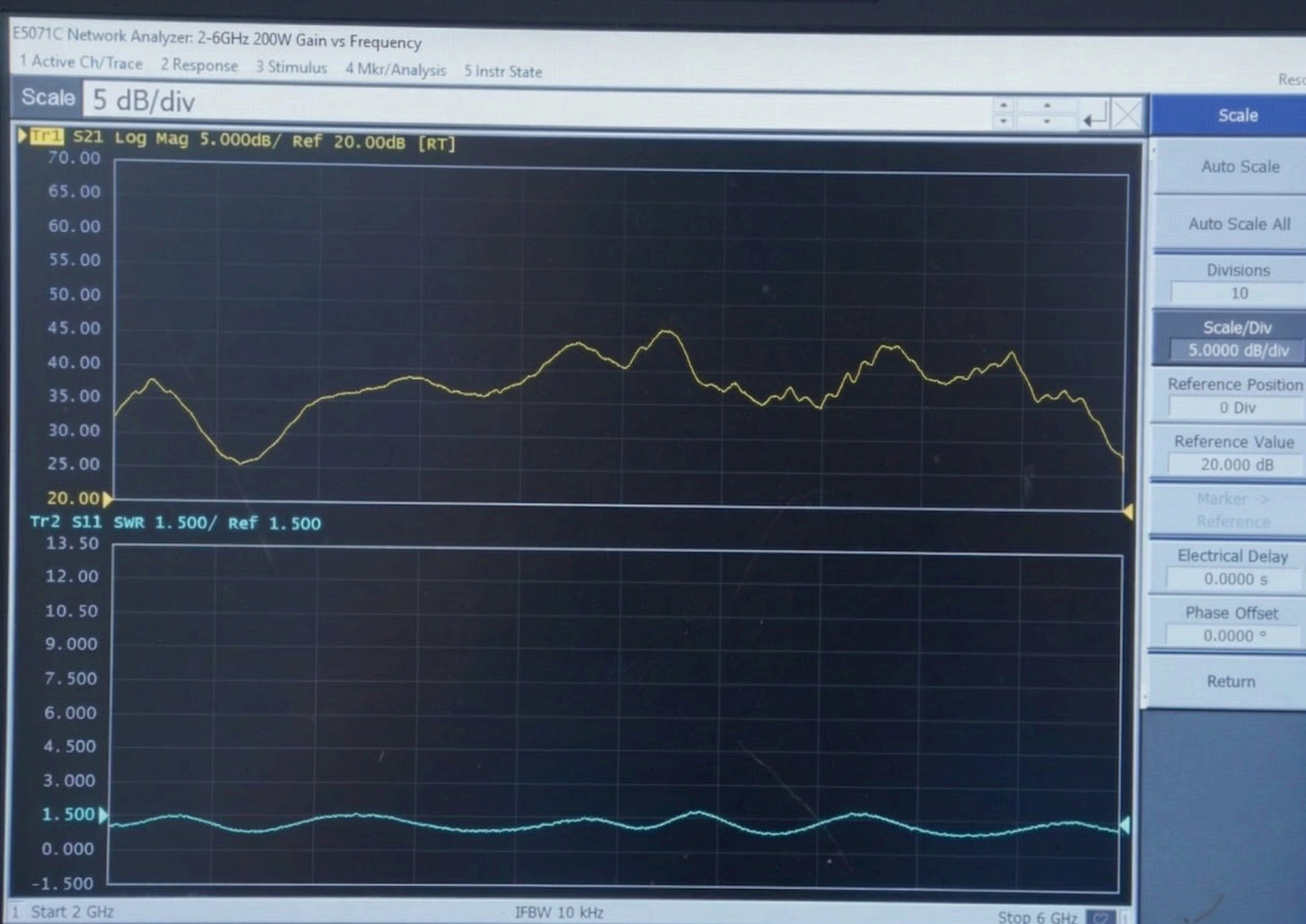
Typical Performance Curves for Engineering Review
Tr1 corresponds to gain (S21, dB). Tr2 corresponds to input match / SWR (S11). Swept measurements are sourced from the datasheet curve pages for each model. Full curve files and S-parameter data are available upon request.
30W — CRF-PA-2G6G-30W
50W — CRF-PA-2G6G-50W
100W — CRF-PA-2G6G-100W
150W — CRF-PA-2G6G-150W
200W — CRF-PA-2G6G-200W
Need full curve files, S-parameter data, or project-specific validation data? Include your project context when requesting.
Mechanical Outline & Connector Reference
For integration buyers, mechanical fit is as important as RF performance. Each datasheet includes a dedicated mechanical outline page for dimensional review and connector location confirmation. Drawings are available before order confirmation.
Compact 30W Format
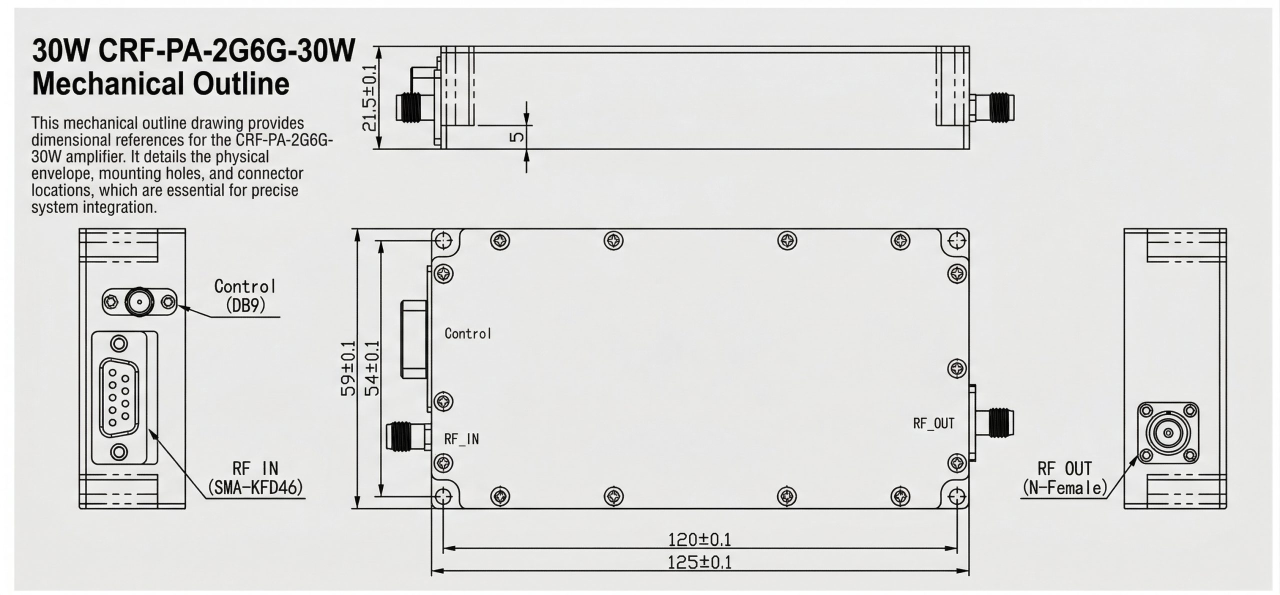
Compact format suitable for bench setups and space-constrained integration environments.
High-Power 50W–200W Platform
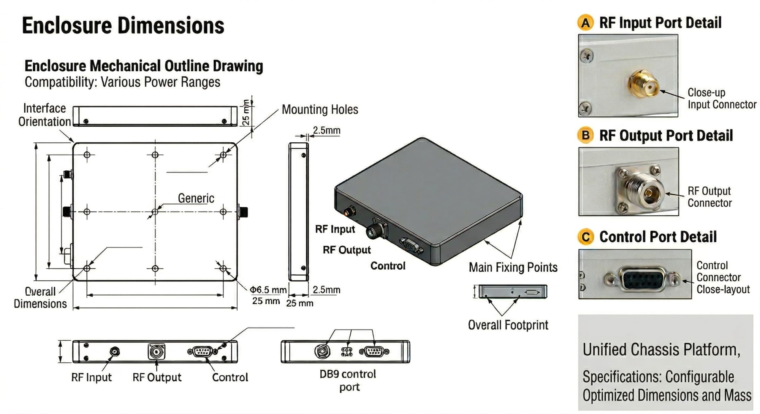
Shared mechanical platform for 50W, 100W, 150W, and 200W. Supply voltage and current consumption vary by output class. Dimensional drawings available before order confirmation.
From RF Validation to Documented Shipment Control
Every unit is supported by a documented process covering RF verification, operational stress testing, precision assembly, and final QC review. Test records are available as part of the delivery package on request.
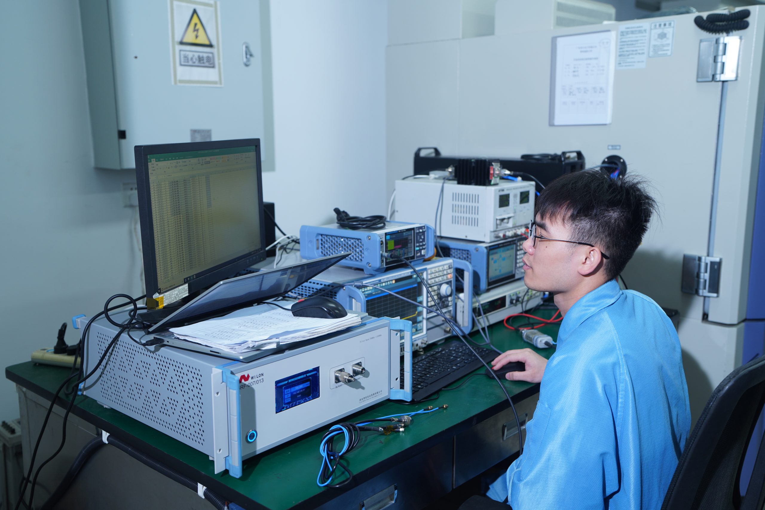
Unit RF Validation
Each unit is linked to an RF verification workflow using calibrated laboratory instruments for model-level performance confirmation.

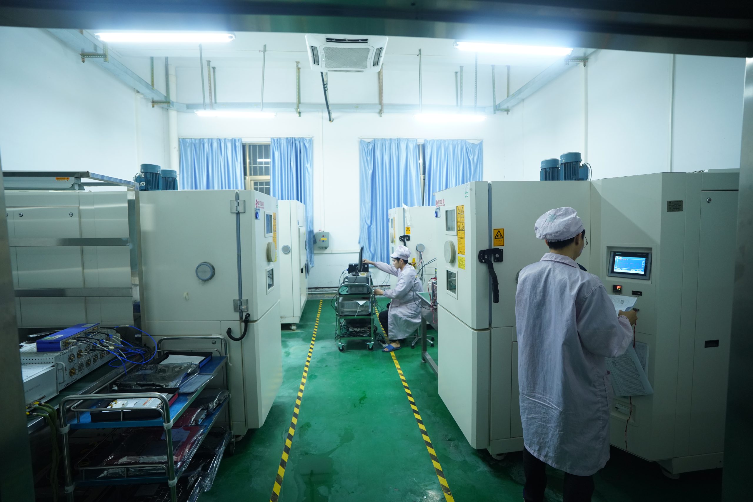
Operational Stress
Soak testing, thermal observation, and load checks confirm hardware stability and performance consistency before delivery.
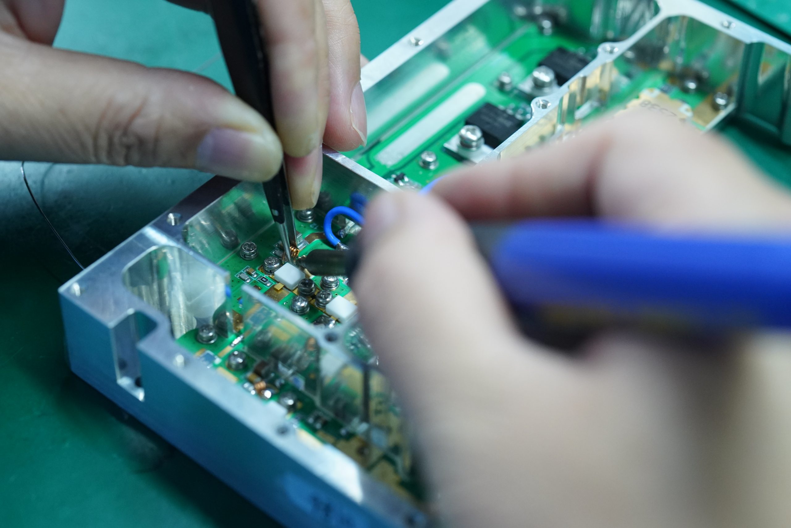
Precision Assembly
Assembly under documented production control supports repeatability across project batches and custom configurations.
Documented QC
Final acceptance records, validation data, and shipment review materials. Unit-level test records provided on request to support technical purchasing decisions.
Customization for Project-Specific Integration
Standard models cover many common project requirements. CorelixRF also supports customization where platform constraints go beyond a catalog configuration. Engineering feasibility review is available within 48 hours — before any volume commitment.
Frequency Adaptation
Request review for a narrower operating window or application-driven band definition outside the standard 2–6 GHz span.
Connector Changes
Connector type and physical interface details can be reviewed for project-specific compatibility and system integration requirements.
Control Interface Adjustment
Control logic and interface requirements can be aligned to customer-side system architecture where feasible.
Mechanical Integration Review
Dimensional and packaging constraints can be discussed before quotation to reduce redesign risk and integration delays.
Send your target frequency, output requirement, duty cycle, supply range, and dimensional constraints for engineering feedback. Feasibility review is available within 48 hours — no volume commitment required to start the conversation.
Technical Documents & Datasheet Requests
Each model in this series is supported by a dedicated datasheet covering electrical characteristics, typical performance curves, and mechanical outline reference. Click any row to request the matching datasheet through the enquiry form — our team will respond within 48 hours.
Need curve files, dimensional drawings, or project-specific validation data? Include your project context in the RFQ form for a more accurate technical review.
Click any row to request via the enquiry form →
Project & Procurement Questions
Common questions from engineers and procurement teams evaluating this series. Can't find what you need? Submit an RFQ — our team will respond within 48 hours.
Is Built For
Discuss Your 2–6 GHz RF Requirement
Send your target frequency, output power, duty cycle, supply range, and expected quantity. Engineering will review feasibility and recommend a suitable standard model or customization path. Sharing connector preferences, dimensional limits, and integration notes up front helps reduce back-and-forth during quotation.
Engineering review · No commitment required · NDA available