
Custom RF Power
Amplifier
Manufacturer
30 MHz to 6 GHz · 30–200W · OEM / ODM
CorelixRF engineers and manufactures custom RF power amplifiers to your frequency, power, supply voltage, connector, mechanical, and thermal requirements. Standard platforms available for faster evaluation — custom development supported from prototype through production.
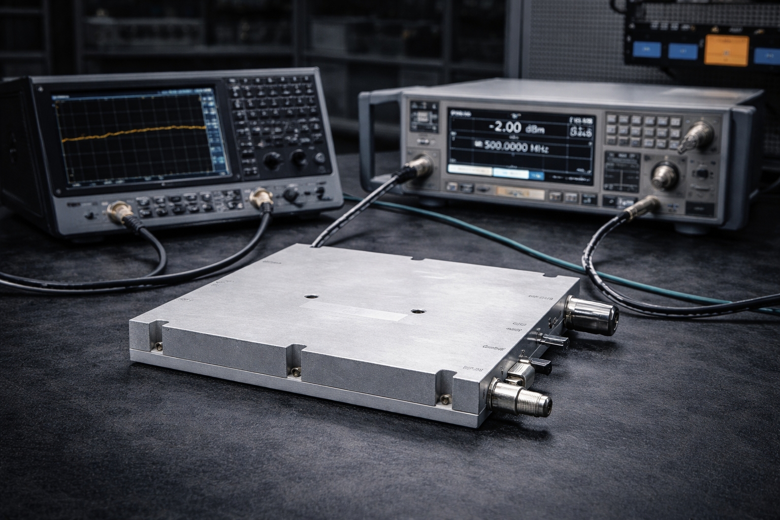
RF Power Amplifier — Main Product Shot
Recommended: 800×600 px, product on dark bg
Why Standard Catalog Products Often Fall Short
Procurement engineers and system integrators regularly encounter these obstacles. If any of these describe your current project, you're in the right place.
Engineering Responses to Real Project Constraints
Each issue has a direct answer. We're not pitching a general OEM service — we're addressing specific technical obstacles your project may be facing.
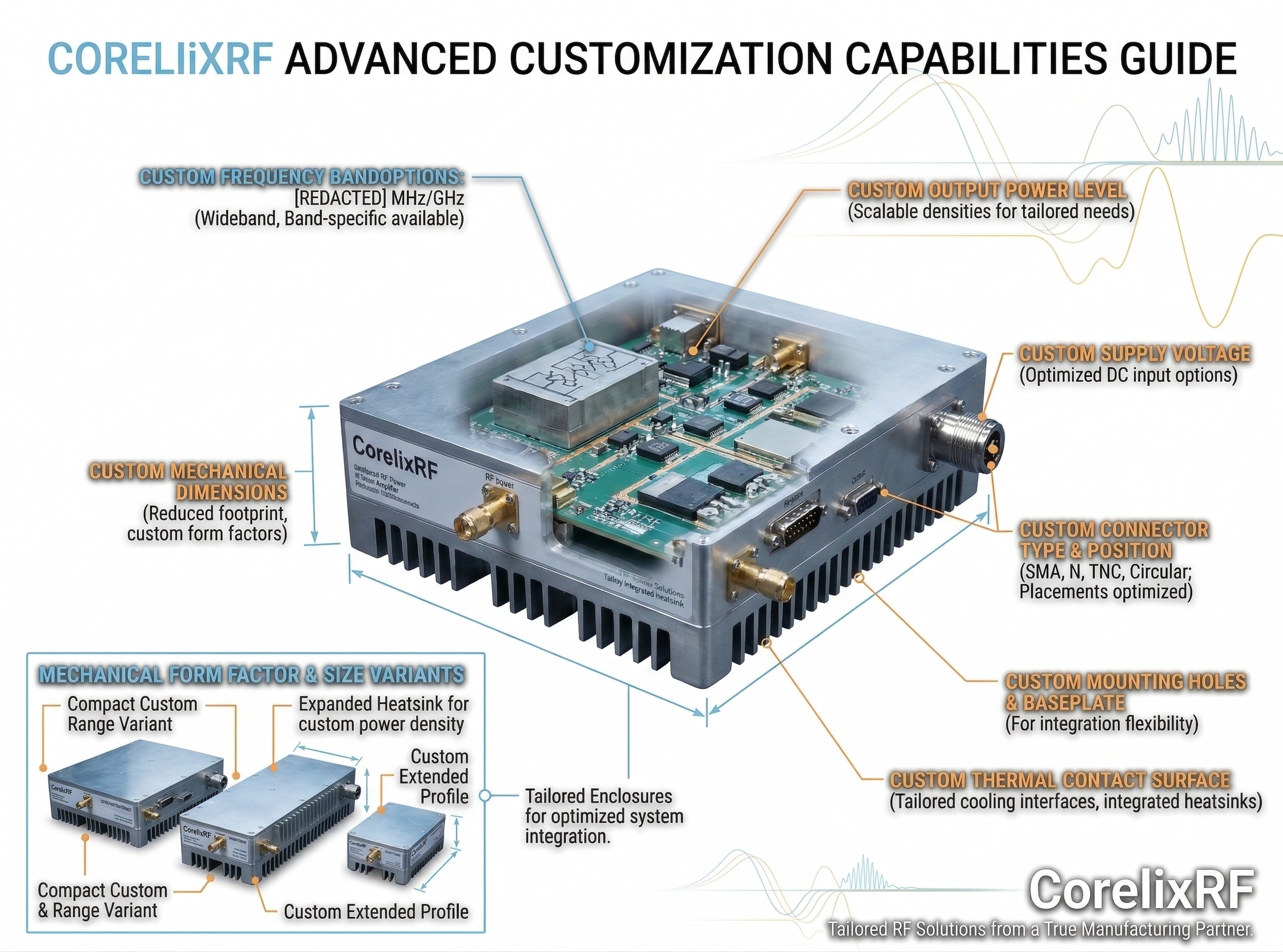
What CorelixRF Can Customize for Your Project
Standard platforms exist to help you evaluate performance and accelerate timelines. But the amplifier going into your system can be matched to your exact requirements across all of these parameters.
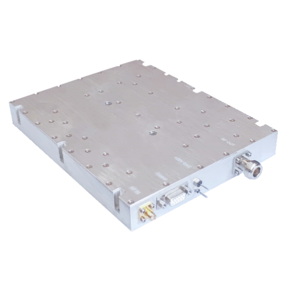
Product photo + callout labels for all 8 custom params
Recommended: 800×600 px
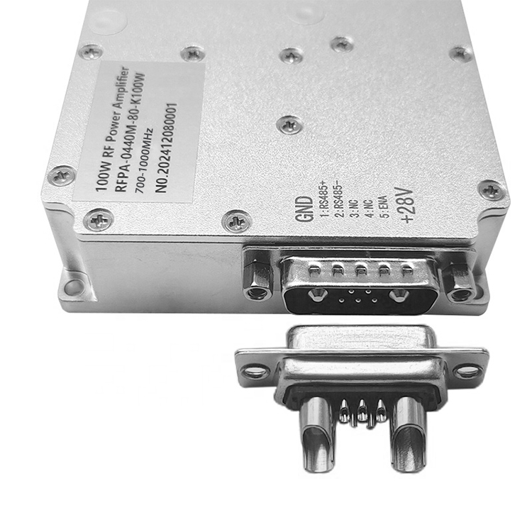
Macro: SMA or N-type connector, or machined baseplate
Aspect 1:1
Have specs ready? Talk directly to the engineering team.
Even a rough frequency range, power level, and voltage spec is enough to start an engineering conversation. Engineering reply typically on the next business day.
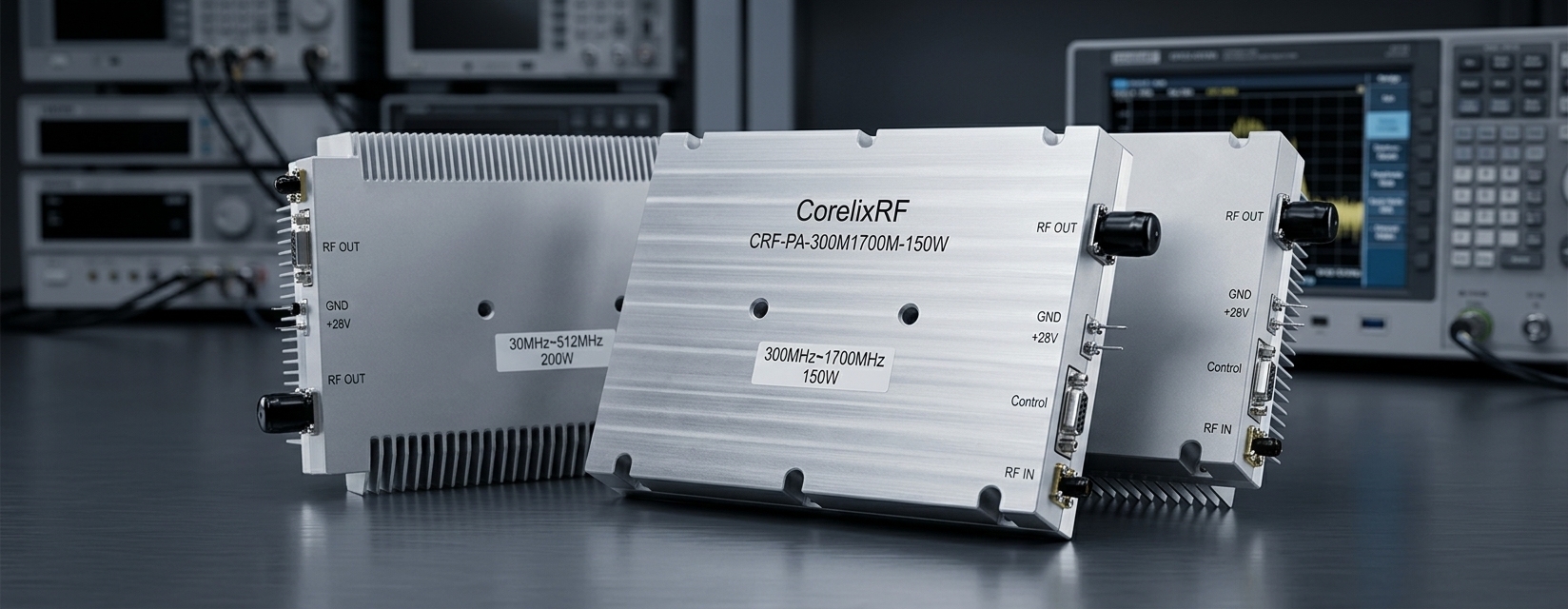
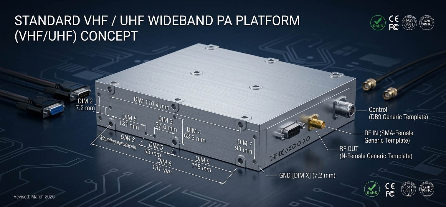
Standard Platforms as a Starting Point for Custom Projects
These platforms represent CorelixRF's validated frequency and power baselines. They help buyers evaluate performance quickly and give our engineering team a known starting point for custom development. They do not represent the limit of what we can build.
Wideband VHF/UHF coverage. Compact 125×59×21.5 mm module at 30–50W. Suitable as baseline for custom sub-band or VDC variants.
View 30–512 MHz Models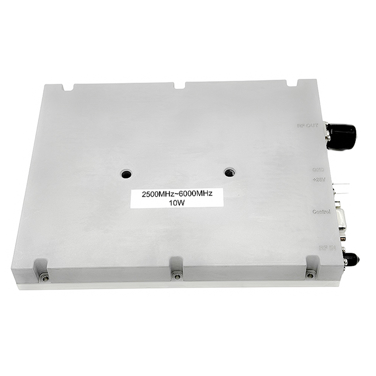
Multi-band broadband coverage. Frequently used as a baseline for communications front-end and wideband RF subsystems requiring consistent gain flatness.
View 300–1700 MHz Models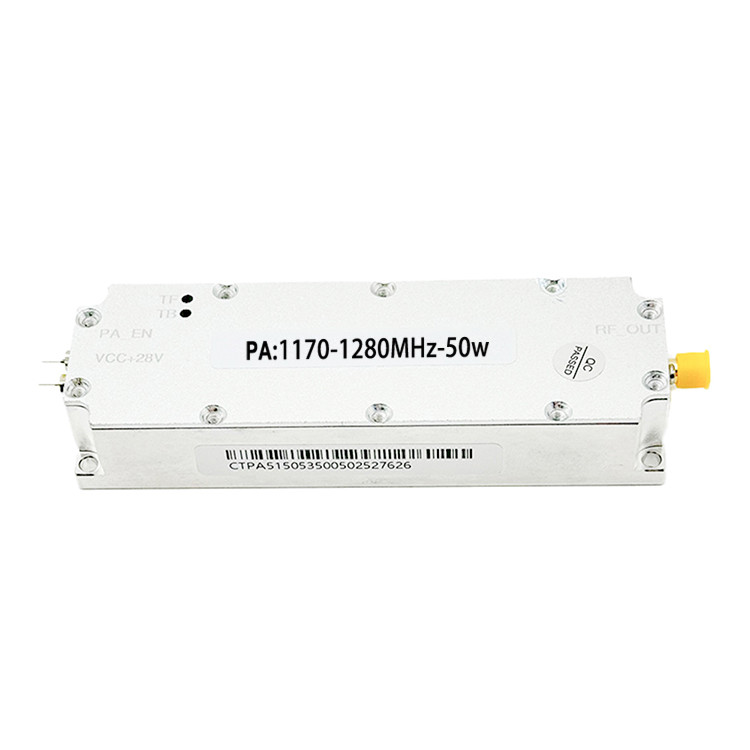
Extended wideband coverage for multi-standard RF integration. One of our most requested standard series — also a strong starting point for extended band OEM builds.
View 300–2700 MHz Models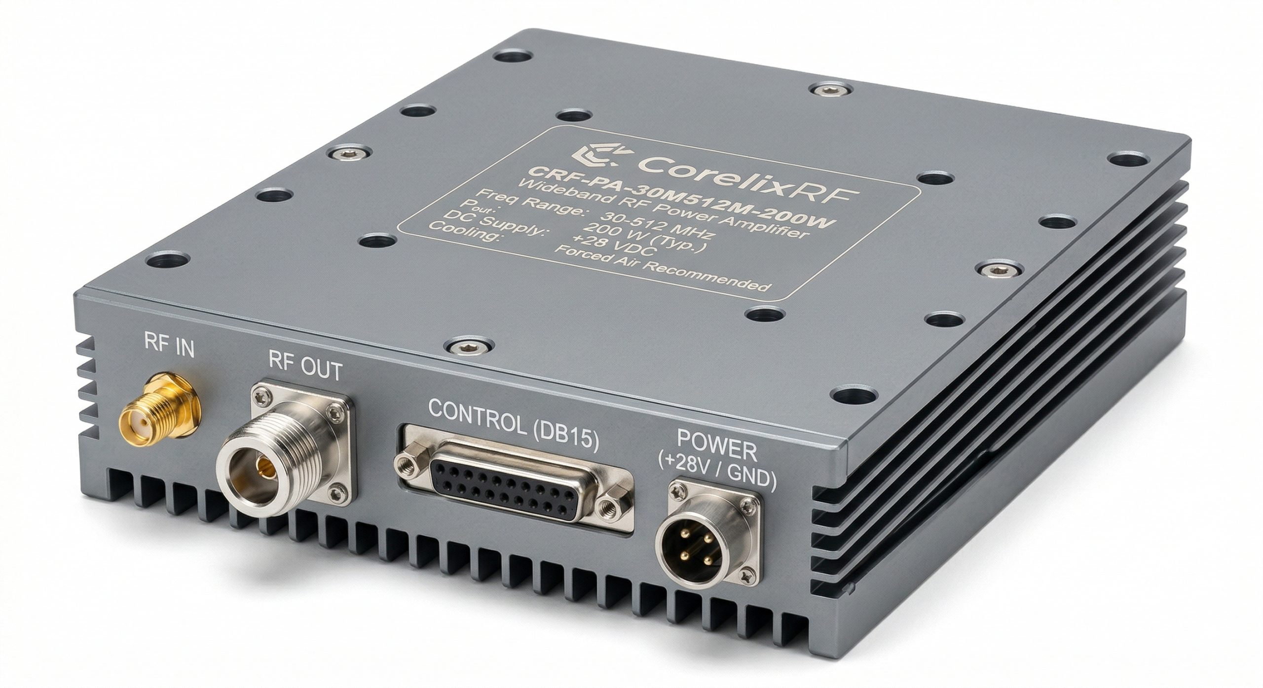
S/C-band wideband. Supply voltage varies per model (36–58V range). Use matrix filter to confirm VDC match, or contact us to discuss a version matched to your supply rail.
View 2–6 GHz ModelsFull Product Matrix — Standard Models
Filter by frequency band, output power, and supply voltage. All models support OEM customization. Use the "Request Datasheet" link to submit specs and receive technical documentation.
| Model | Freq Range (MHz) | Pout (W) | Pout (dBm) | Pin (dBm) | VSWR | Harmonics | VDC | Imax (A) | Size (mm) | Weight (kg) | Cooling | Connector | Datasheet | Quote |
|---|---|---|---|---|---|---|---|---|---|---|---|---|---|---|
| CRF-PA-30M512M-30W | 30–512 | 30 | 45±1 | 0–8 | ≤ 1.8 | ≥ 10 dBc | 28 | ≤ 4 | 125×59×21.5 | ≤ 0.5 | Air Cooling | SMA/N | Request DS | RFQ |
| CRF-PA-30M512M-50W | 30–512 | 50 | 47±1 | 0–8 | ≤ 1.8 | ≥ 10 dBc | 28 | ≤ 9 | 125×59×21.5 | ≤ 0.5 | Air Cooling | SMA/N | Request DS | RFQ |
| CRF-PA-30M512M-100W | 30–512 | 100 | 50±1 | 0–8 | ≤ 1.8 | ≥ 10 dBc | 28 | ≤ 18 | 200×158×25 | ≤ 1.4 | Air Cooling | SMA/N | Request DS | RFQ |
| CRF-PA-30M512M-150W | 30–512 | 150 | 52±1 | 0–8 | ≤ 1.8 | ≥ 10 dBc | 28 | ≤ 20 | 200×158×25 | ≤ 1.4 | Air Cooling | SMA/N | Request DS | RFQ |
| CRF-PA-30M512M-200W | 30–512 | 200 | 53±1 | 0–8 | ≤ 1.8 | ≥ 10 dBc | 28 | ≤ 30 | 200×158×25 | ≤ 1.4 | Air Cooling | SMA/N | Request DS | RFQ |
| CRF-PA-300M1700M-30W | 300–1700 | 30 | 45±1 | 0–8 | ≤ 1.8 | ≥ 10 dBc | 28 | ≤ 3 | 125×59×21.5 | ≤ 0.5 | Air Cooling | SMA/N | Request DS | RFQ |
| CRF-PA-300M1700M-50W | 300–1700 | 50 | 47±1 | 0–8 | ≤ 1.8 | ≥ 10 dBc | 28 | ≤ 7 | 125×59×21.5 | ≤ 0.5 | Air Cooling | SMA/N | Request DS | RFQ |
| CRF-PA-300M1700M-100W | 300–1700 | 100 | 50±1 | 0–8 | ≤ 1.8 | ≥ 10 dBc | 28 | ≤ 14 | 200×158×25 | ≤ 1.4 | Air Cooling | SMA/N | Request DS | RFQ |
| CRF-PA-300M1700M-150W | 300–1700 | 150 | 52±1 | 0–8 | ≤ 1.8 | ≥ 10 dBc | 28 | ≤ 22 | 200×158×25 | ≤ 1.4 | Air Cooling | SMA/N | Request DS | RFQ |
| CRF-PA-300M1700M-200W | 300–1700 | 200 | 53±1 | 0–8 | ≤ 1.8 | ≥ 10 dBc | 28 | ≤ 29 | 200×158×25 | ≤ 1.4 | Air Cooling | SMA/N | Request DS | RFQ |
| CRF-PA-300M2700M-30W | 300–2700 | 30 | 45±1 | 0–8 | ≤ 1.8 | ≥ 10 dBc | 28 | ≤ 4 | 125×59×21.5 | ≤ 0.5 | Air Cooling | SMA/N | Request DS | RFQ |
| CRF-PA-300M2700M-50W | 300–2700 | 50 | 47±1 | 0–8 | ≤ 1.8 | ≥ 10 dBc | 28 | ≤ 9 | 125×59×21.5 | ≤ 0.5 | Air Cooling | SMA/N | Request DS | RFQ |
| CRF-PA-300M2700M-100W | 300–2700 | 100 | 50±1 | 0–8 | ≤ 1.5 | ≥ 10 dBc | 28 | ≤ 18 | 200×158×25 | ≤ 1.4 | Air Cooling | SMA/N | Request DS | RFQ |
| CRF-PA-300M2700M-150W | 300–2700 | 150 | 52±1 | 0–8 | ≤ 1.5 | ≥ 10 dBc | 28 | ≤ 20 | 200×158×25 | ≤ 1.4 | Air Cooling | SMA/N | Request DS | RFQ |
| CRF-PA-300M2700M-200W | 300–2700 | 200 | 53±1 | 0–8 | ≤ 1.8 | ≥ 10 dBc | 28 | ≤ 36 | 200×158×25 | ≤ 1.4 | Air Cooling | SMA/N | Request DS | RFQ |
| CRF-PA-2G6G-30W | 2000–6000 | 30 | 45±1 | 0–8 | ≤ 1.8 | ≥ 10 dBc | 36–46V | ≤ 4 | 125×59×21.5 | ≤ 0.5 | Air Cooling | SMA/N | Request DS | RFQ |
| CRF-PA-2G6G-50W | 2000–6000 | 50 | 47±1 | -1–6 | ≤ 1.8 | ≥ 10 dBc | 40–58V | ≤ 12 | 200×158×25 | ≤ 1.4 | Air Cooling | SMA/N | Request DS | RFQ |
| CRF-PA-2G6G-100W | 2000–6000 | 100 | 50±1 | -7–6 | ≤ 1.8 | ≥ 10 dBc | 41–51V | ≤ 24 | 200×158×25 | ≤ 1.4 | Air Cooling | SMA/N | Request DS | RFQ |
| CRF-PA-2G6G-150W | 2000–6000 | 150 | 52±1 | 0–8 | ≤ 1.8 | ≥ 10 dBc | 43–58V | ≤ 27 | 200×158×25 | ≤ 1.4 | Air Cooling | SMA/N | Request DS | RFQ |
| CRF-PA-2G6G-200W | 2000–6000 | 200 | 53±1 | 0–8 | ≤ 1.8 | ≥ 10 dBc | 44–54V | ≤ 36 | 200×158×25 | ≤ 1.4 | Air Cooling | SMA/N | Request DS | RFQ |
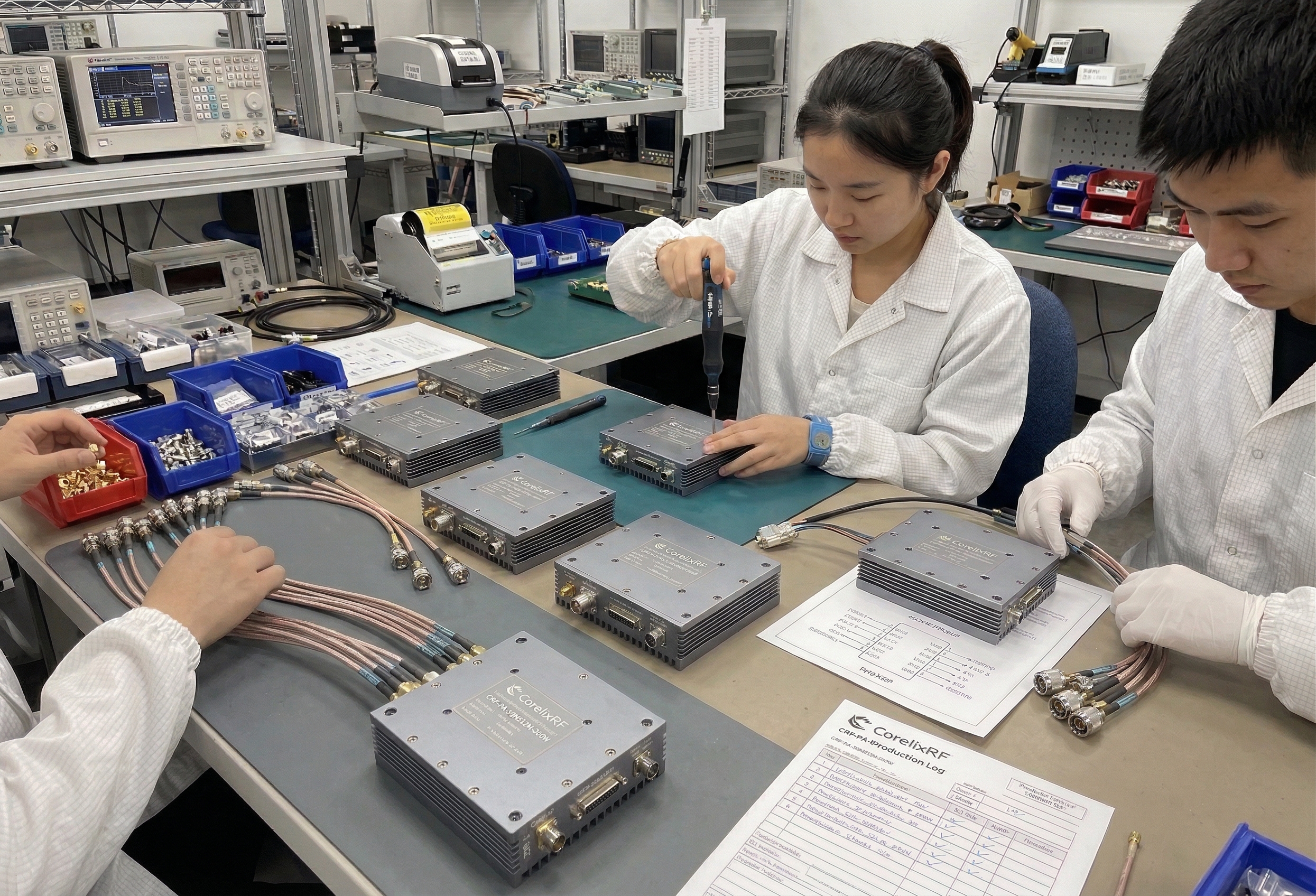
Why CorelixRF Is Relevant to Your Amplifier Project
This is not a generic about-us section. These are the specific reasons CorelixRF is suited for OEM, system integration, and project-based amplifier development.
Suggest: test bench scene, engineering team, or assembly floor
Recommended: 1200×675 px
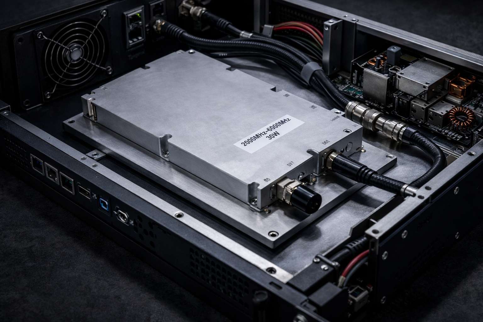
Finished module / product close-up
Assembly / QC inspection scene
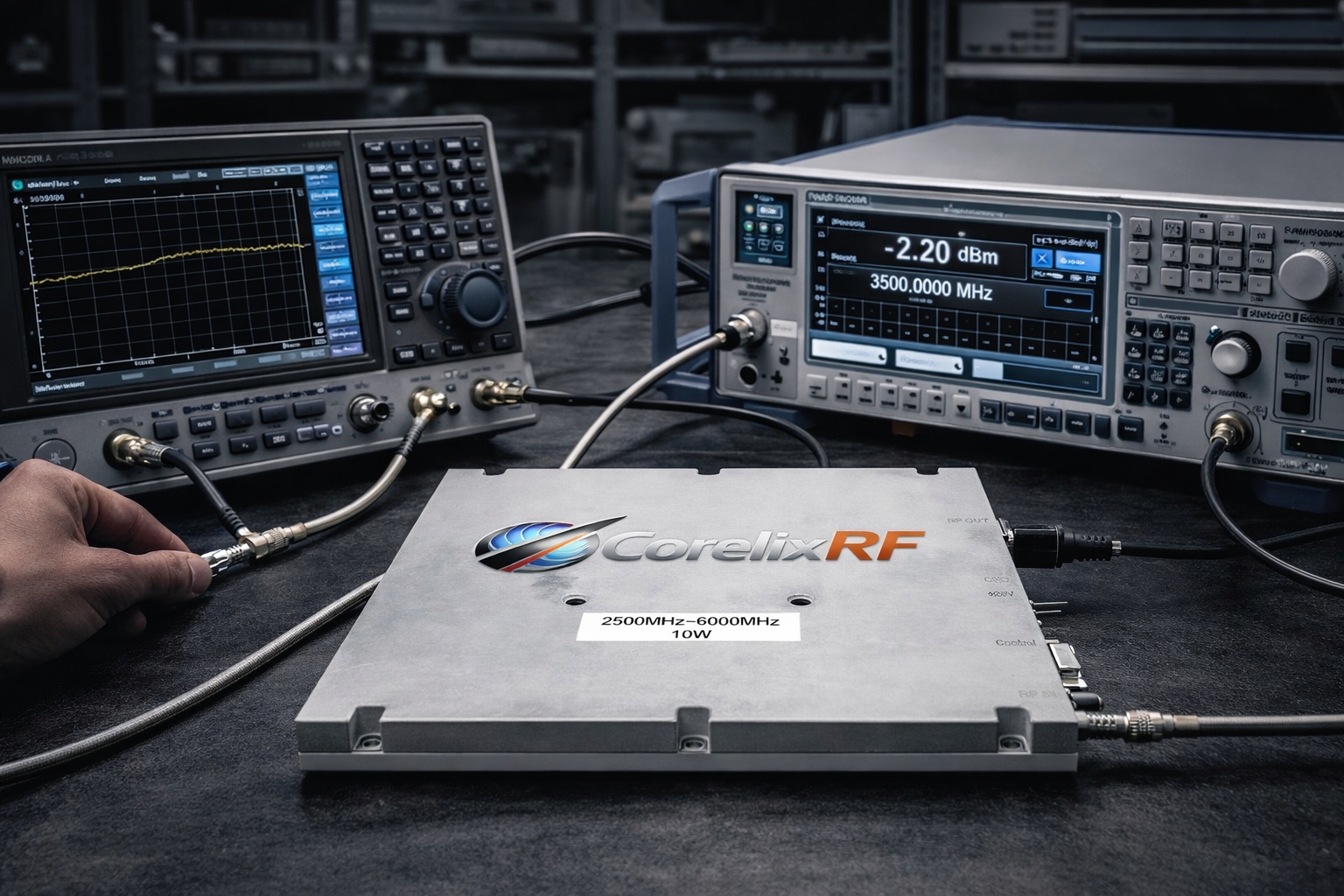
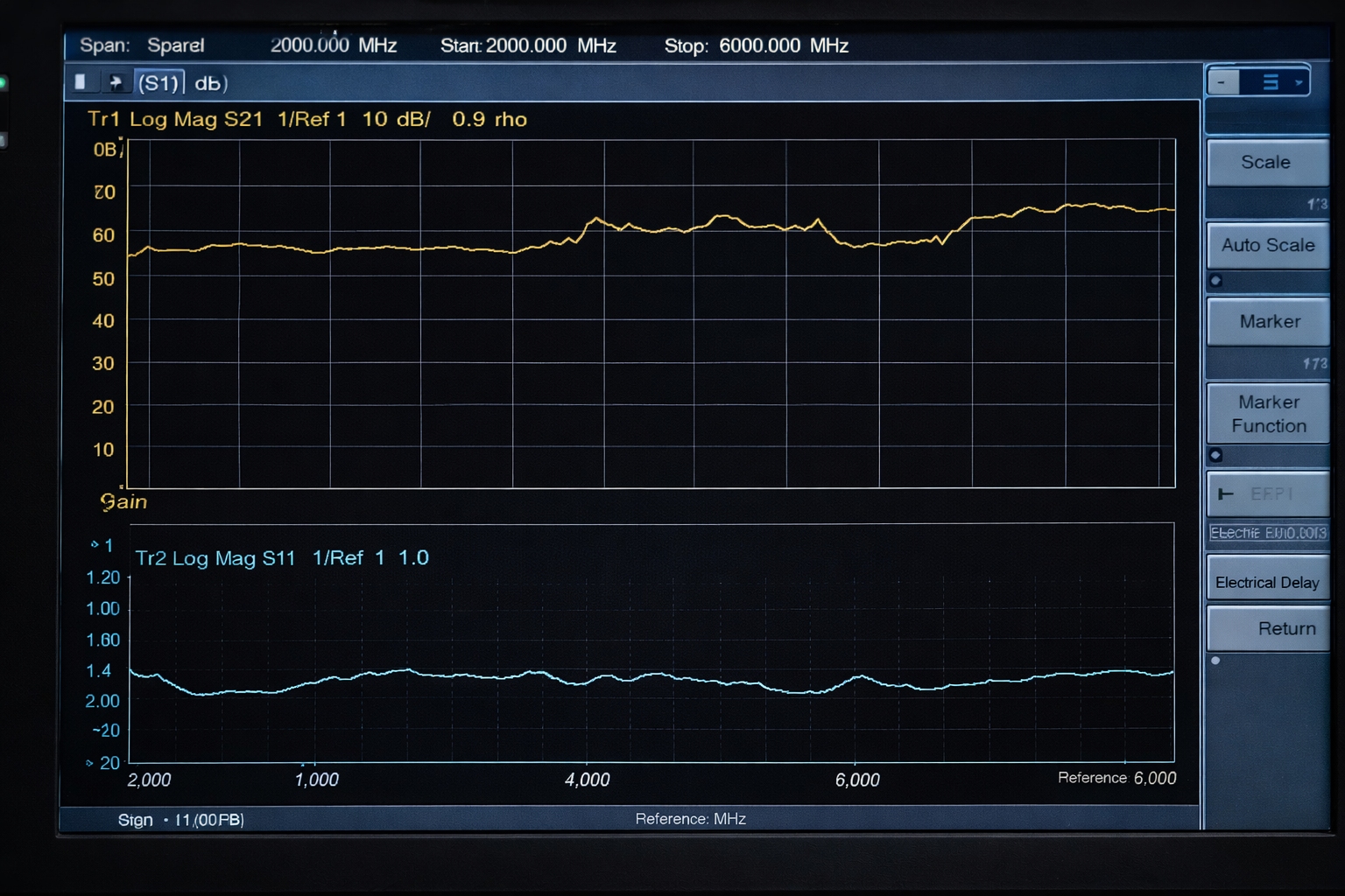
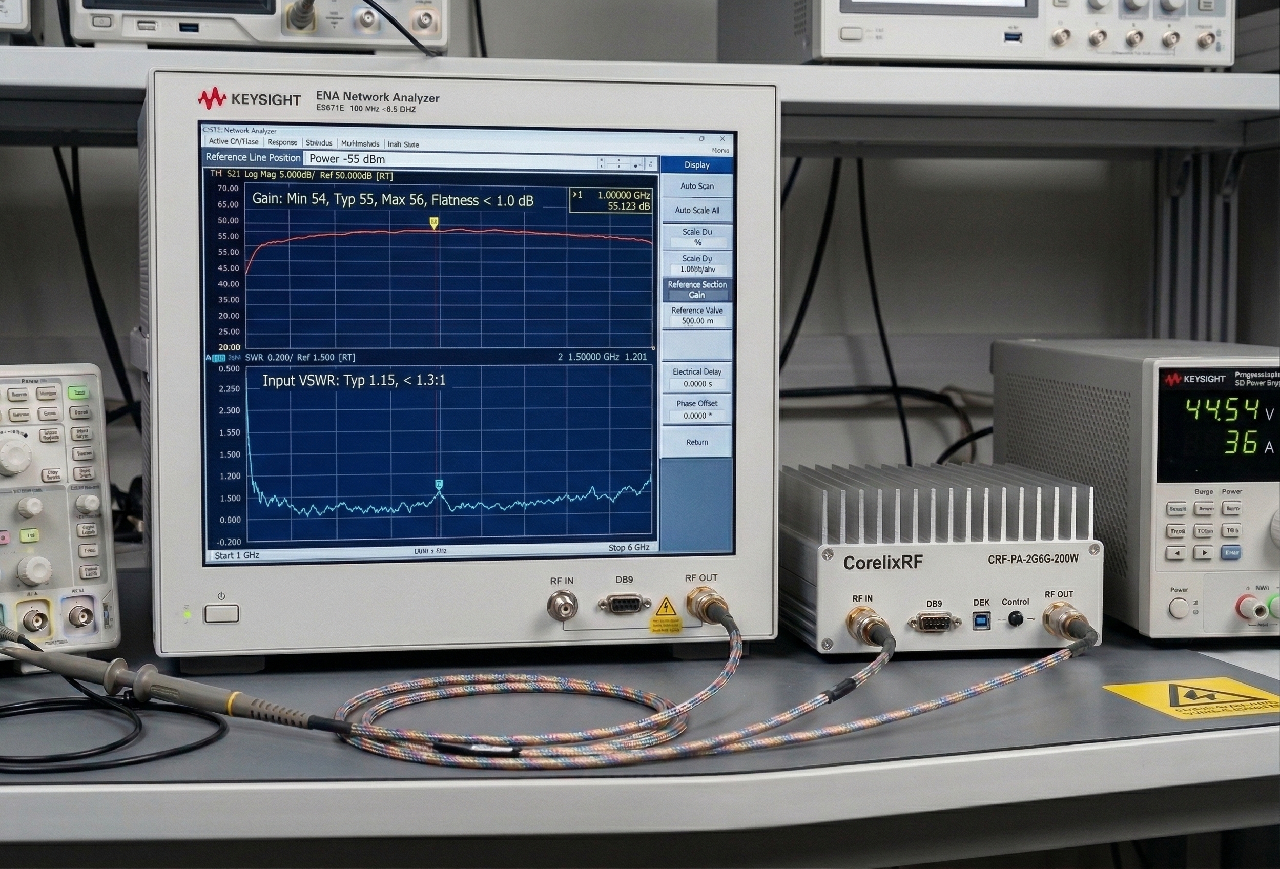
Validation Process That Reduces Your Procurement Risk
Test data and validation documentation exist to give buyers confidence before committing to production volume. Here's what CorelixRF provides at each stage.
RF test bench / full setup
Recommended: 1200×675 px
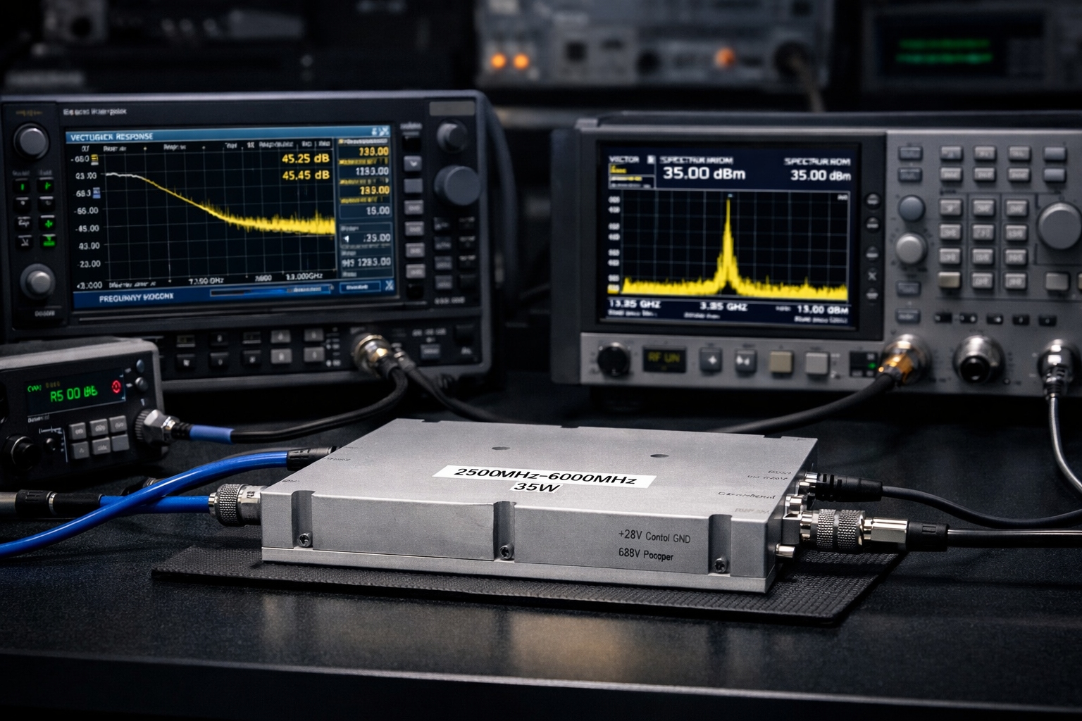
VNA / spectrum screen
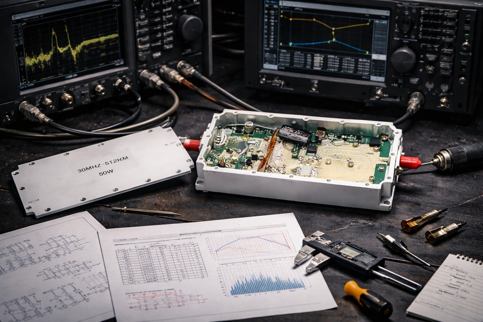
Thermal imaging
Projects Where CorelixRF Custom Amplifiers Are Relevant
These are the project types where custom RF power amplifier development makes engineering and commercial sense, and where CorelixRF has direct experience.
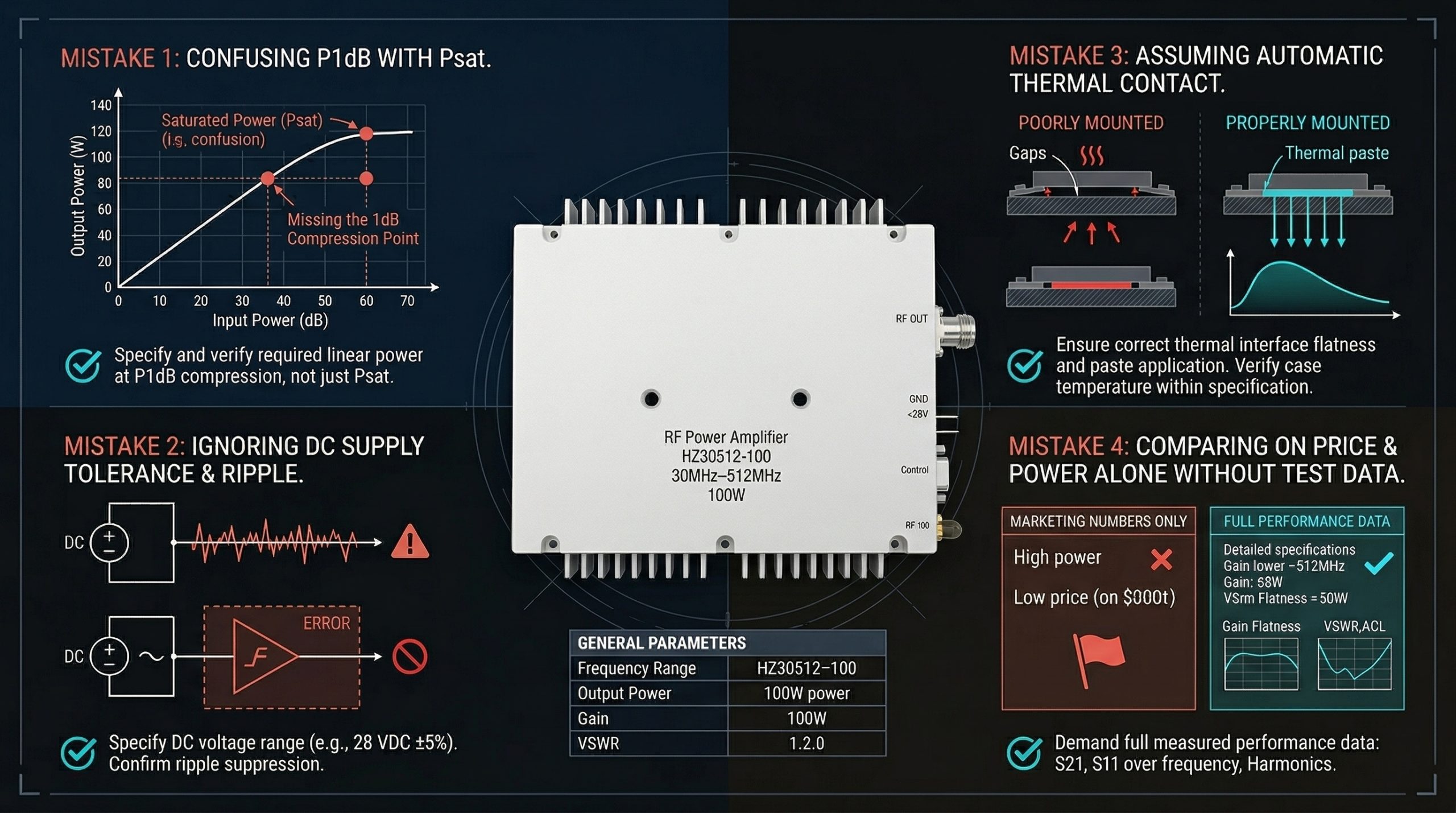
Common RF Amplifier Procurement Mistakes — And How to Avoid Them
These mistakes are worth knowing about before you place a first order or commit to a supplier. They're not obvious from a datasheet, but they affect project outcomes consistently.
Suggest: Psat vs P1dB curve diagram, or procurement checklist infographic
Keep minimal — support role only
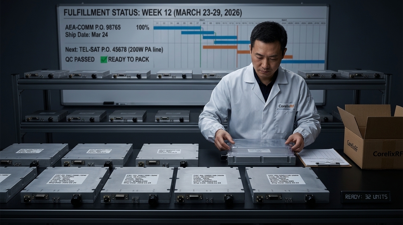
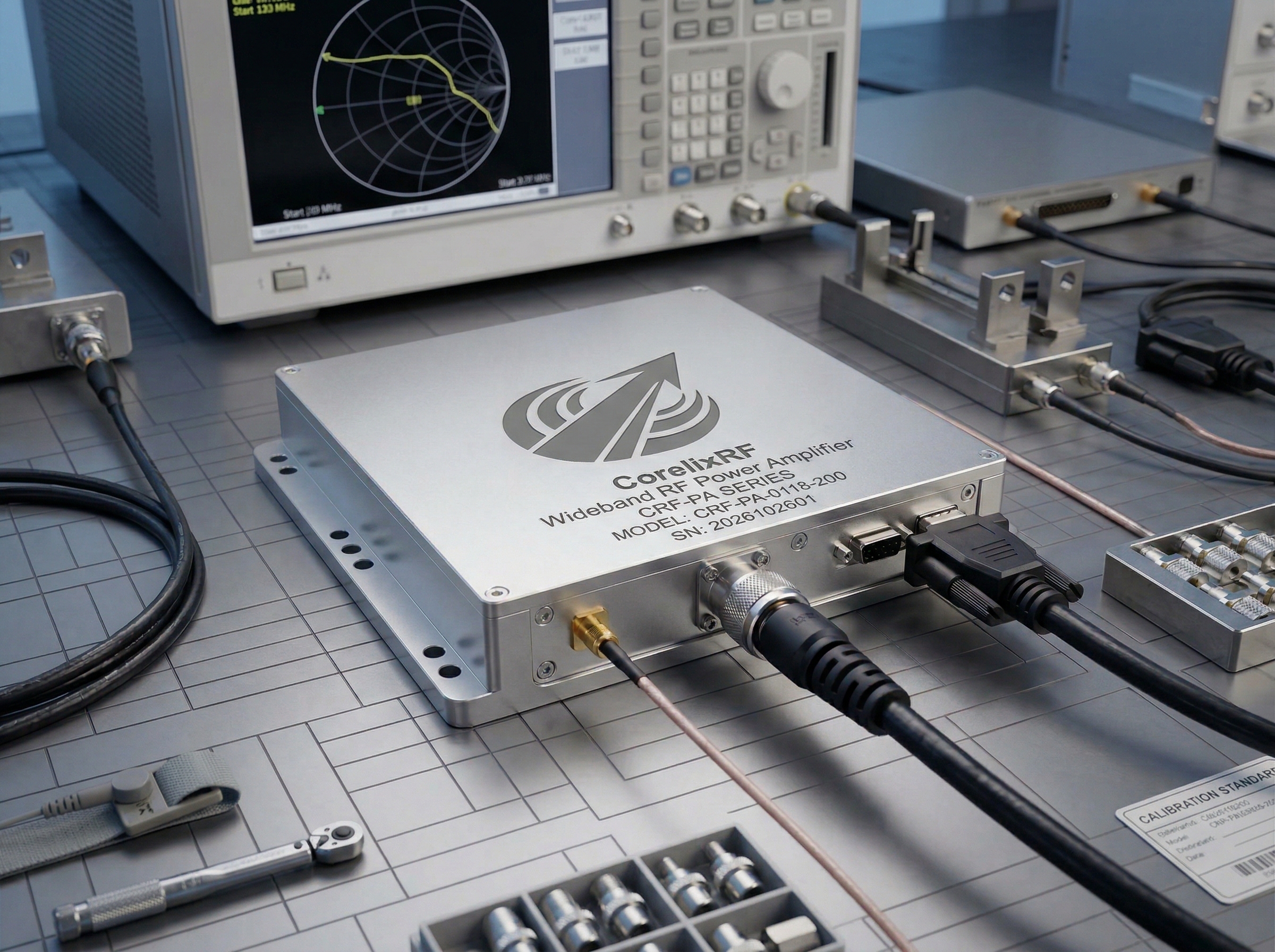
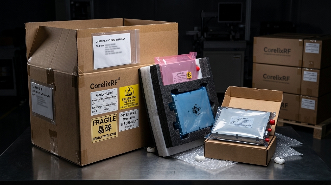
Factory-Direct Manufacturing and Reliable Export Delivery
CorelixRF manufactures, assembles, tests, and ships from our own facility. This section covers the operational side of what we can deliver.
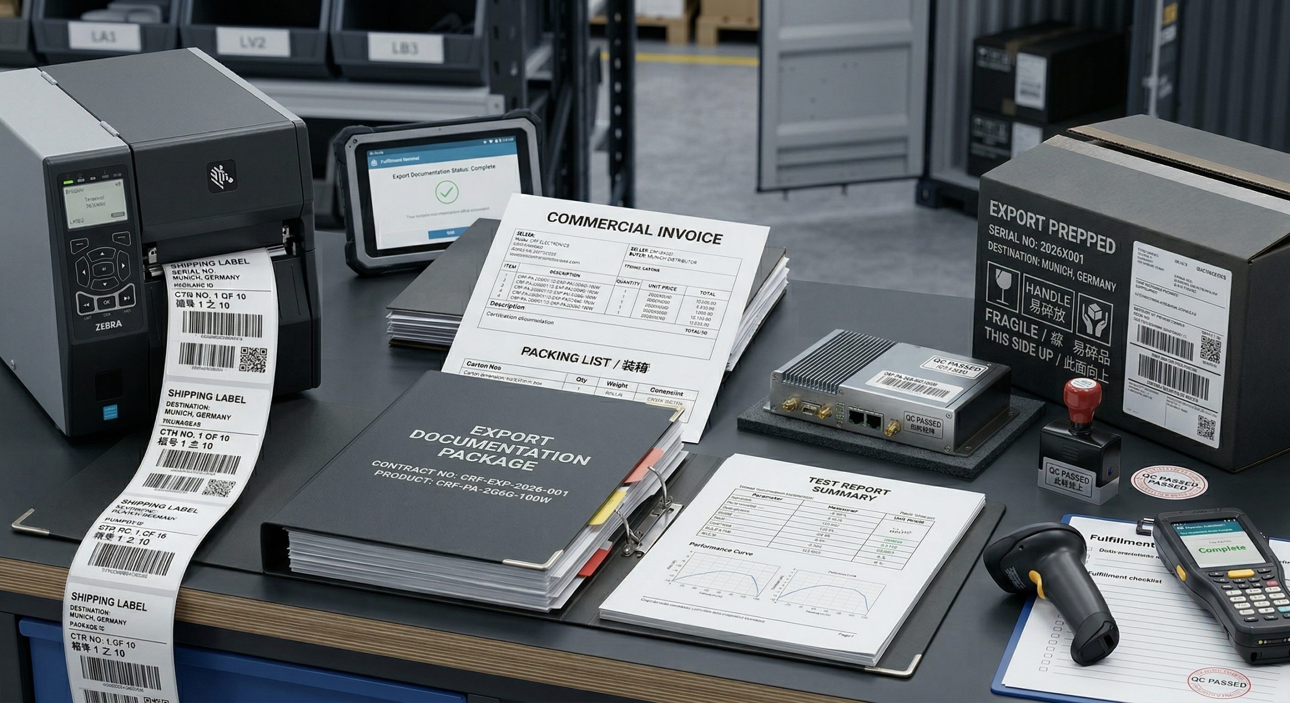

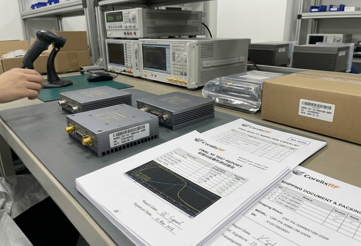
Quality System and Documentation Support
Certifications are the floor, not the ceiling. What matters is how the quality system supports OEM project handling and documentation requirements.

ISO 9001 Certificate
Test Report / Traceability Record

NDA / Confidential Documentation
Questions Engineers and Procurement Buyers Actually Ask
Straight answers on the specification and procurement questions that affect integration decisions.
Talk Directly to Engineering
Your specifications go directly to the CorelixRF RF engineering team. Not a quoting desk. Not a reseller. The people who respond design and build these modules. Engineering reply typically on the next business day.