
Factory-Direct RF Power Amplifier Solutions
for Integration, Validation, and OEM Projects
CorelixRF provides factory-direct RF power amplifier platforms covering 30 MHz to 6 GHz for OEM integration, engineering validation, and project-based customization. Start with standard band platforms, compare real integration constraints, and move to in-house custom execution when required.
What Buyers Need to Confirm Before Choosing an RF Power Amplifier
Choosing an RF power amplifier is rarely only about output power. In real projects, band coverage, gain behavior, supply condition, thermal path, connector type, and protection logic all affect whether a module can actually be integrated with confidence.
The first step is confirming the amplifier family matches the real operating band — not only a nominal target frequency. Selecting by the correct band family reduces mismatch early and improves the efficiency of follow-up comparison.
Output class and gain behavior must align with the upstream source and downstream RF chain. Across the current standard datasheets, representative gain is typically 45–53 dB depending on band and output class, while gain flatness is commonly specified at ≤1.8 dB and reaches ≤1.5 dB on selected models.
Gain flatness: typically ≤1.8 dB, selected models ≤1.5 dB
The 30–512 MHz, 300–1700 MHz, and 300–2700 MHz platforms use 28 VDC. The 2–6 GHz platform uses model-dependent supply ranges, so supply condition should be confirmed before model selection.
300–1700 MHz 200W ≤29 A
2–6 GHz 50W ≤12 A
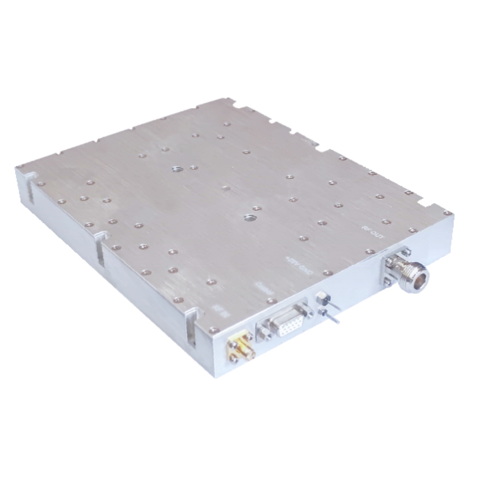
Cooling method and package size should be confirmed by model before installation. Thermal and mechanical planning should begin at module selection — not after installation. Mounting hole patterns and physical dimensions are documented per model.
and 200 × 158 × 25 mm, depending on model and output class
Control interface and protection details should be confirmed at model level. Current datasheets show DB9 control reference, while project-specific monitoring and protection details can be reviewed during engineering discussion.
Model-level protection details: confirm during engineering review
Current standard datasheets specify SMA-Female input and N-Female output. Connector type is confirmed during engineering consultation before a recommendation is made. For custom connector requirements, OEM/ODM paths are available.
Output VSWR: commonly specified at ≤2.0 :1
This is why customers usually start with a verified factory platform rather than a generic amplifier listing.
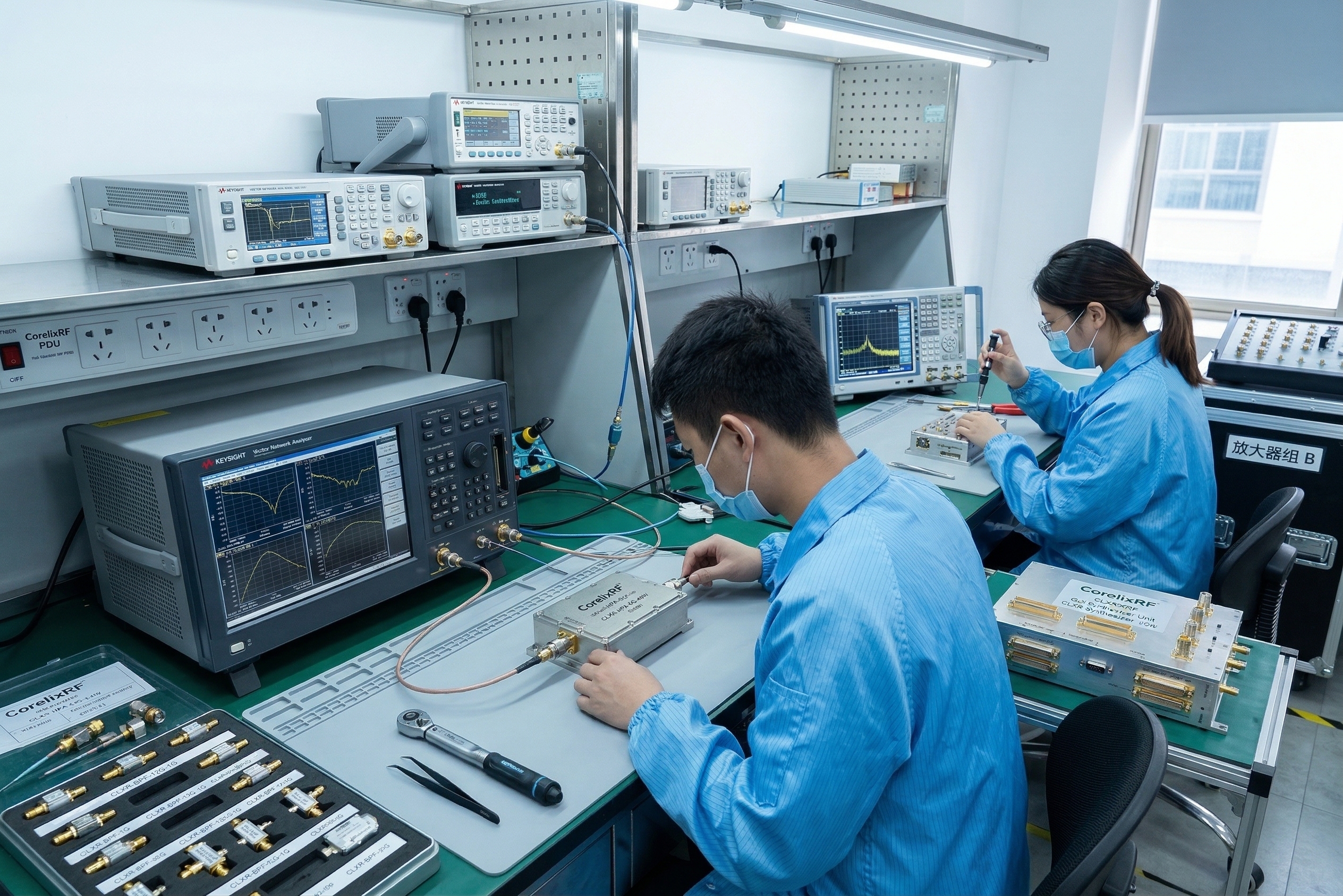
Why CorelixRF — Factory Identity Behind the Platform
What separates a direct manufacturer from a trading company or system integrator is verifiable production and quality capability. Here is what in-house manufacturing means for your project.
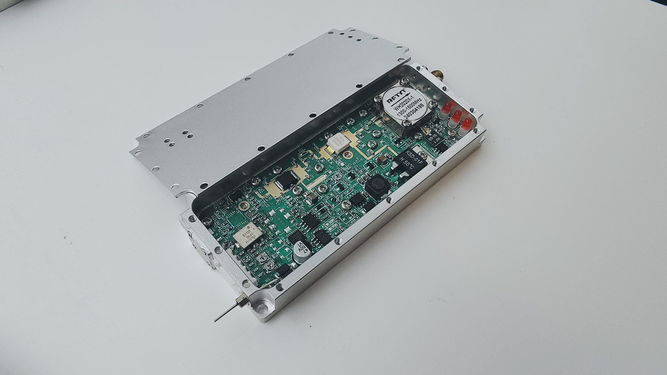
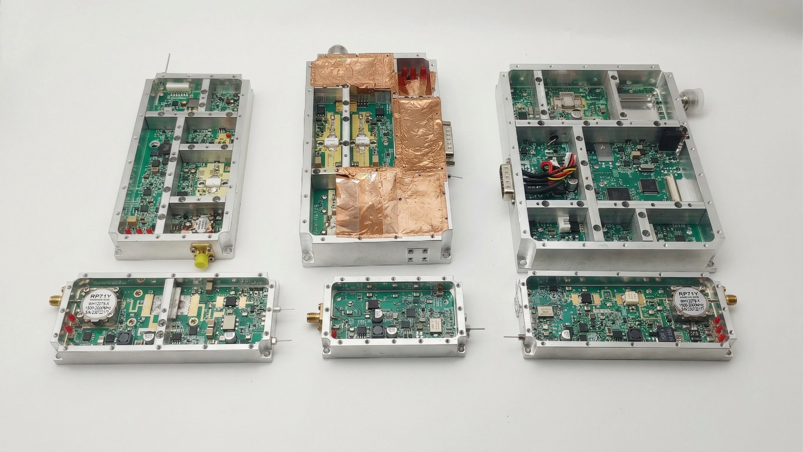
Amplifier assembly, RF tuning, final inspection, and production workflow are conducted in-house. This means direct quality control, faster response on engineering changes, and no third-party manufacturing dependencies on standard platform orders.
Standard platforms are not assembled on a per-order basis — they are established production lines with documented specifications, validated module configurations, and consistent output across batches. This reduces risk for customers moving from sample to production quantities.
Standard modules are reviewed for RF output, supply condition, interface reference, and project-level validation requirements before shipment. Additional protection and monitoring details can be confirmed during engineering review.
When standard platforms do not fully match a project, custom directions are executed with factory engineering involvement — not subcontracted. Connector changes, housing adaptation, output class adjustment, and mechanical outline modification are all handled in-house from requirement through prototype and production.
Explore Standard RF Power Amplifier Platforms by Frequency Band
Select the platform that best matches your system band. Each platform is a mature in-house production line — not a concept — with documented output levels, supply conditions, and integration requirements for faster comparison and project entry.
These are standard production-ready platforms used as the starting point for both immediate selection and project-specific customization.
For VHF/UHF projects and broadband sub-1 GHz systems requiring stable performance across the full band. Current standard datasheets specify 28 VDC operation, Air Cooling, SMA-Female input, and N-Female output across the platform family.
For broadband mid-band RF systems across UHF to L-band. The current 300–1700 MHz platform is defined in the uploaded datasheets as a wideband family with 28 VDC operation, model-dependent gain progression by output class, and SMA-Female input / N-Female output configuration.
Covers a larger portion of the RF chain on one platform. SKU structures include 30W, 50W, 100W, 150W, and 200W output levels with documented VSWR, harmonics, size, and current limits per output class — in-house manufactured with consistent batch output.
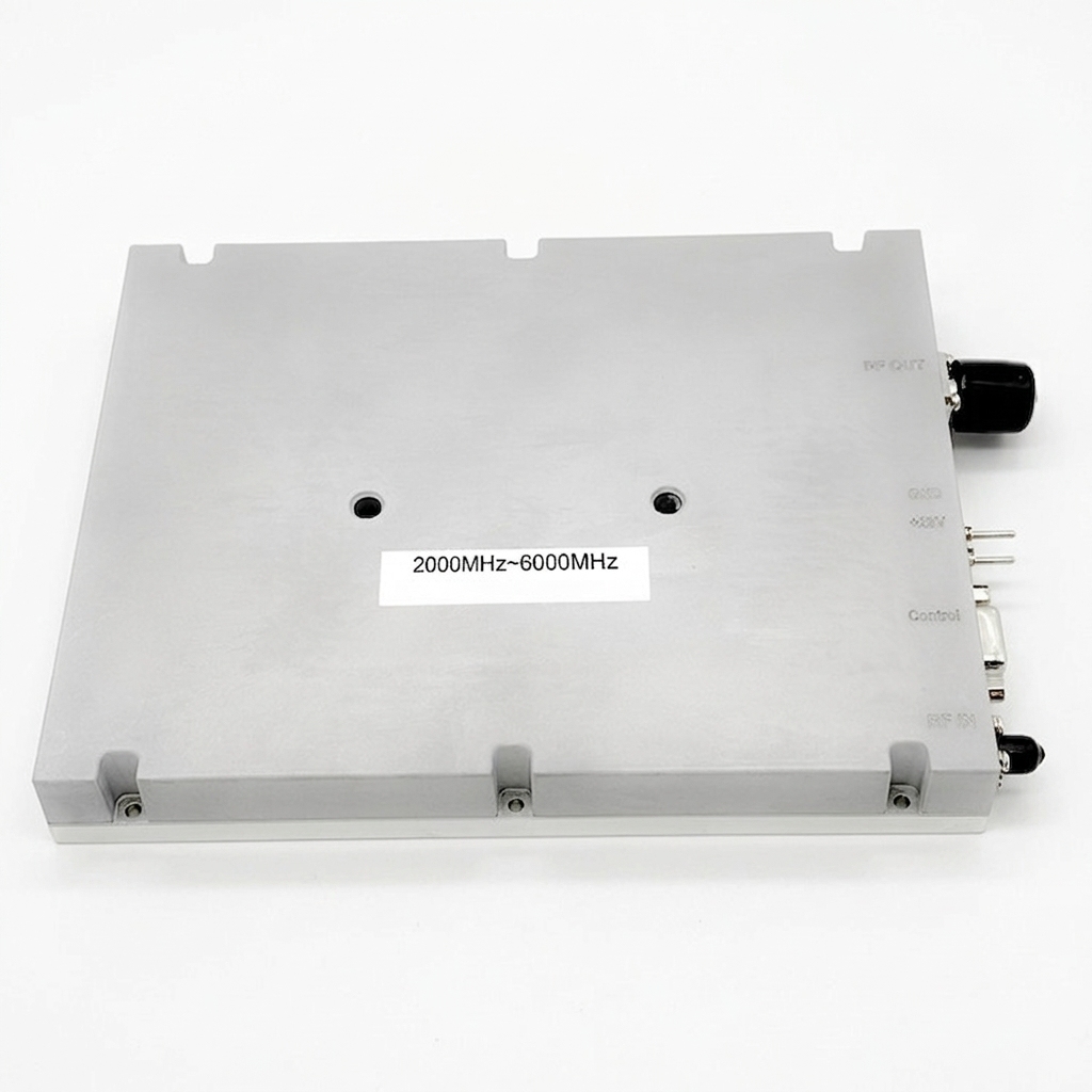
For upper-band integration where thermal planning, gain behavior, and output constraints become more critical. ⚠ Supply voltage varies by model (Multi-VDC) — confirm supply before selection. The current uploaded datasheets define this platform as a 2,000–6,000 MHz wideband family with model-dependent supply ranges and output classes from 30W to 200W.
Need a non-standard combination of band, output, or package? Custom RF amplifier projects are supported with OEM/ODM execution from factory requirement review through production.
Representative Models for Fast Comparison
Below are representative modules. Additional band- and power-specific models are available on each platform page. Use this matrix to compare by frequency band, output power, supply condition, connector type, and integration suitability before moving into detailed project discussion.
| Module | Freq Range | Rated Output Power | Gain (Typ) | Flatness | DC Supply | Current Consumption | RF Connector | Size (mm) | Action |
|---|---|---|---|---|---|---|---|---|---|
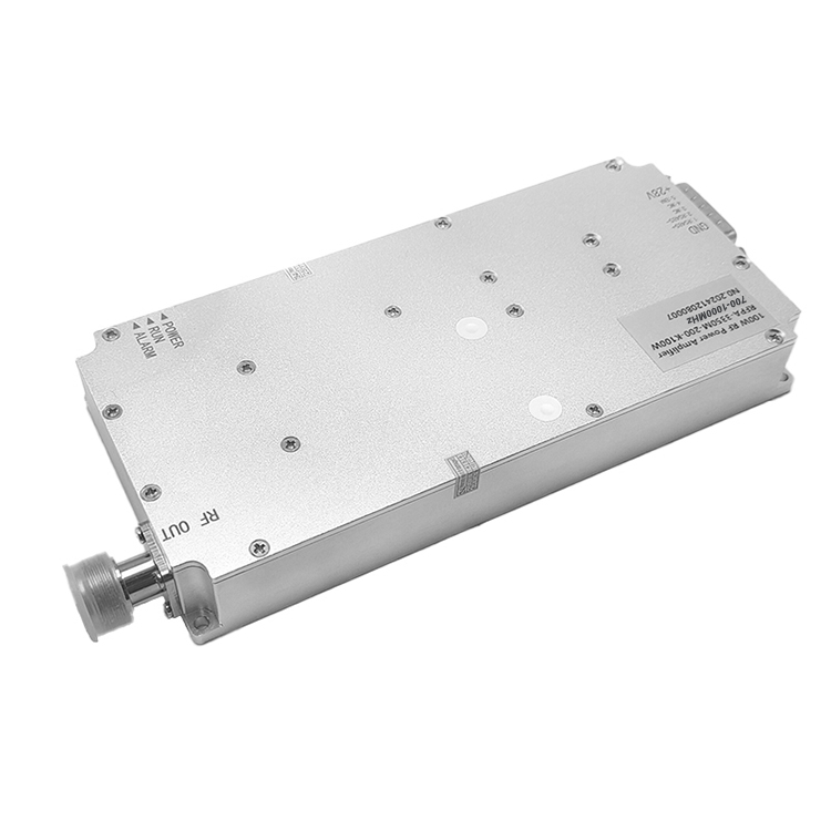
| CRF-PA-30M512M-200W | 30–512 MHz | 200 W | 52–54 dB | ≤1.8 dB | DC 28V | ≤30 A | SMA-F IN / N-F OUT | 200 × 158 × 25 | Request Datasheet RFQ |
| CRF-PA-300M1700M-200W | 300–1700 MHz | 200 W | 52–54 dB | ≤1.8 dB | DC 28V | ≤29 A | SMA-F IN / N-F OUT | 200 × 158 × 25 | Request Datasheet RFQ |
| CRF-PA-300M2700M-150W | 300–2700 MHz | 150 W | 51–53 dB | ≤1.5 dB | DC 28V | ≤20 A | SMA-F IN / N-F OUT | 200 × 158 × 25 | Request Datasheet RFQ |
| CRF-PA-2G6G-50W | 2,000–6,000 MHz | 50 W | 46–48 dB | ≤1.8 dB | 40–58 VDC | ≤12 A | SMA-F IN / N-F OUT | 200 × 158 × 25 | Request Datasheet RFQ |
| CRF-PA-2G6G-150W | 2,000–6,000 MHz | 150 W | 51–53 dB | ≤1.8 dB | 43–58 VDC | ≤27 A | SMA-F IN / N-F OUT | 200 × 158 × 25 | Request Datasheet RFQ |
Technical Validation Evidence Behind the Solution
Before recommending any platform, CorelixRF reviews the technical conditions that determine whether a module can be integrated with confidence — reducing the risk of mismatch, rework, and unexpected constraints after procurement.
We confirm whether the amplifier platform matches the intended RF operating band. Platforms are structured around 30–512 MHz, 300–1700 MHz, 300–2700 MHz, and 2–6 GHz — letting customers start selection by band before narrowing to output level and integration details.
This prevents band mismatch from surfacing late in the project after mechanical integration has already begun.
We review whether output class and gain behavior are suitable for the target system. Across current standard datasheets, representative gain is typically 45–53 dB depending on band and output class, with flatness commonly ≤1.8 dB and ≤1.5 dB on selected models.
This reduces uncertainty before power budgeting and RF chain design are finalized.
We review whether the available supply condition is practical for the chosen amplifier platform. The 30–512 MHz, 300–1700 MHz, and 300–2700 MHz platforms use 28 VDC. The 2–6 GHz platform uses model-dependent supply ranges — supply is a selection parameter.
This prevents supply incompatibility from being discovered after the module has been specified into a larger system.
Cooling method and package size should be confirmed by model before installation. Current datasheets list Air Cooling across the standard platform set. Amplifier selection is often limited by available space and mechanical envelope — not only RF performance. Documented modules include physical dimensions and mounting references.
This reduces uncertainty before mechanical integration and enclosure design, where thermal conflicts are most costly to correct.
Control interface and protection details should be confirmed at model level. Current datasheets reference DB9 control interface. Project-specific monitoring and protection details — including over-temperature behavior, standing wave response, and enable control — are reviewed during engineering discussion before recommendation.
This means customers receive a module with confirmed protection behavior — reducing integration risk before deployment sign-off.
What Is Standard and What Can Be Customized
Most projects start with a standard amplifier platform, then refine details based on integration constraints. This shortens development time while leaving room for OEM/ODM adaptation where needed.
RF Amplifier Solutions for Typical Project Scenarios
Different projects place different constraints on amplifier choice. These are common scenarios where customers use standard platforms for integration, validation, or OEM development — all sourced factory direct.
Customers building a broader RF chain need to confirm the amplifier platform is appropriate before full system assembly begins. Band fit, gain behavior, drive level, supply condition, cooling method — all verified against the full source-to-amplifier-to-antenna path. Factory engineering support available.
Standard production-ready platforms allow OEM teams to evaluate real integration constraints early — before mechanical design is locked in.
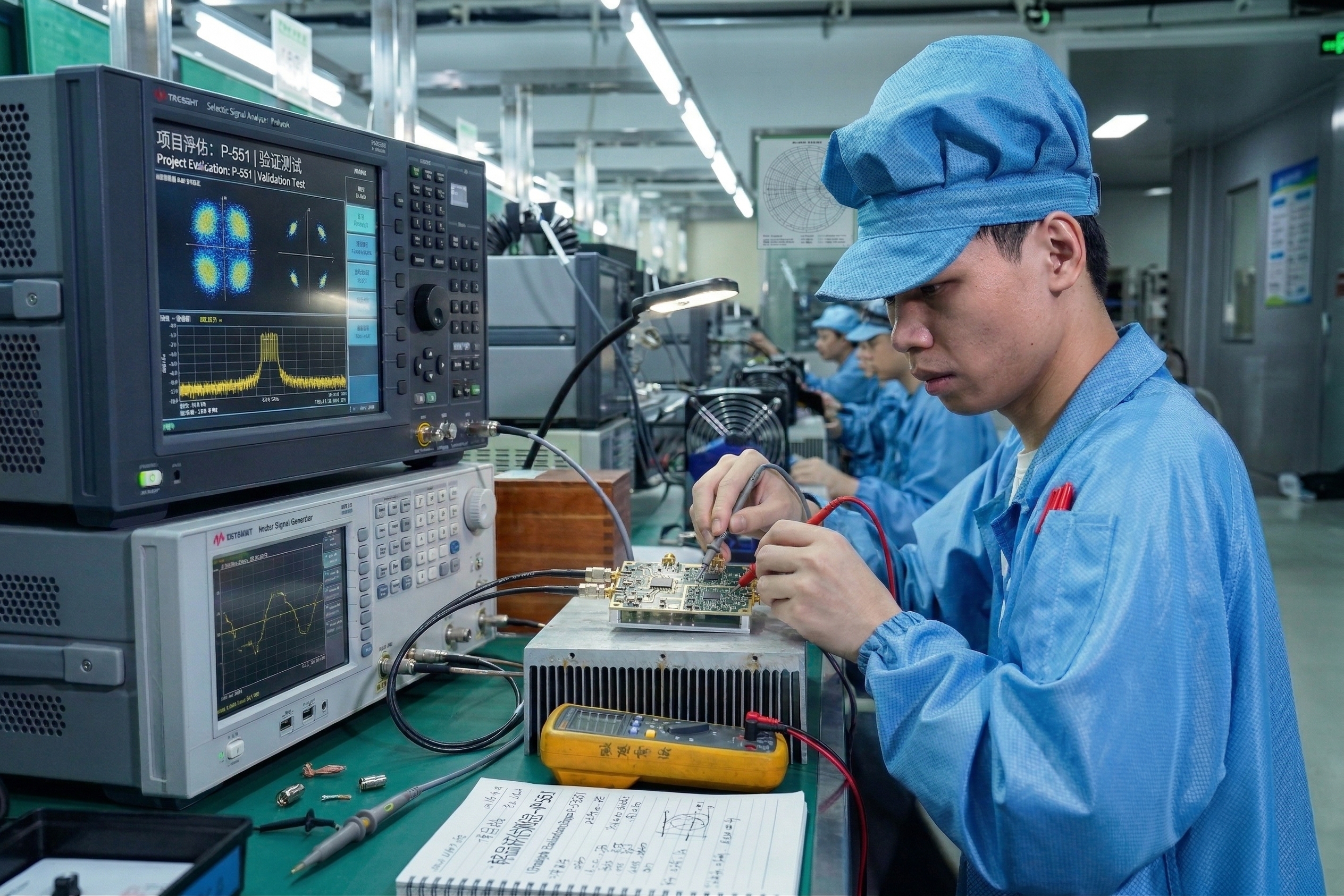
Projects using SDR front-ends for lab evaluation or pre-deployment validation require amplifier modules with predictable gain, documented protection behavior, and repeatable output. Standard production modules backed by factory test data reduce uncertainty before the module enters a larger signal chain.
Documented gain flatness and unit-level test data let engineering teams validate the full signal path without relying on nominal datasheet assumptions.
Communications projects covering wider frequency ranges need amplifier platforms that reduce early-stage option counts. Wideband standard families across 300–2700 MHz are suited for projects where bandwidth flexibility matters and the final architecture is still being defined.
A single wideband platform family shortens selection time and gives engineering teams a production-ready reference before committing to a custom direction.
Upper-band RF projects in the 2–6 GHz range require careful attention to thermal design, supply confirmation, and output constraints. Standard 5 GHz and C-band platforms provide a verified starting point for engineering teams working on upper-band integration — with OEM/ODM customization available when project-specific requirements go beyond the standard platform.
Factory-direct supply and batch delivery capability support both prototype evaluation and production-scale deployment requirements.
How CorelixRF Supports Your Project from Selection to Delivery
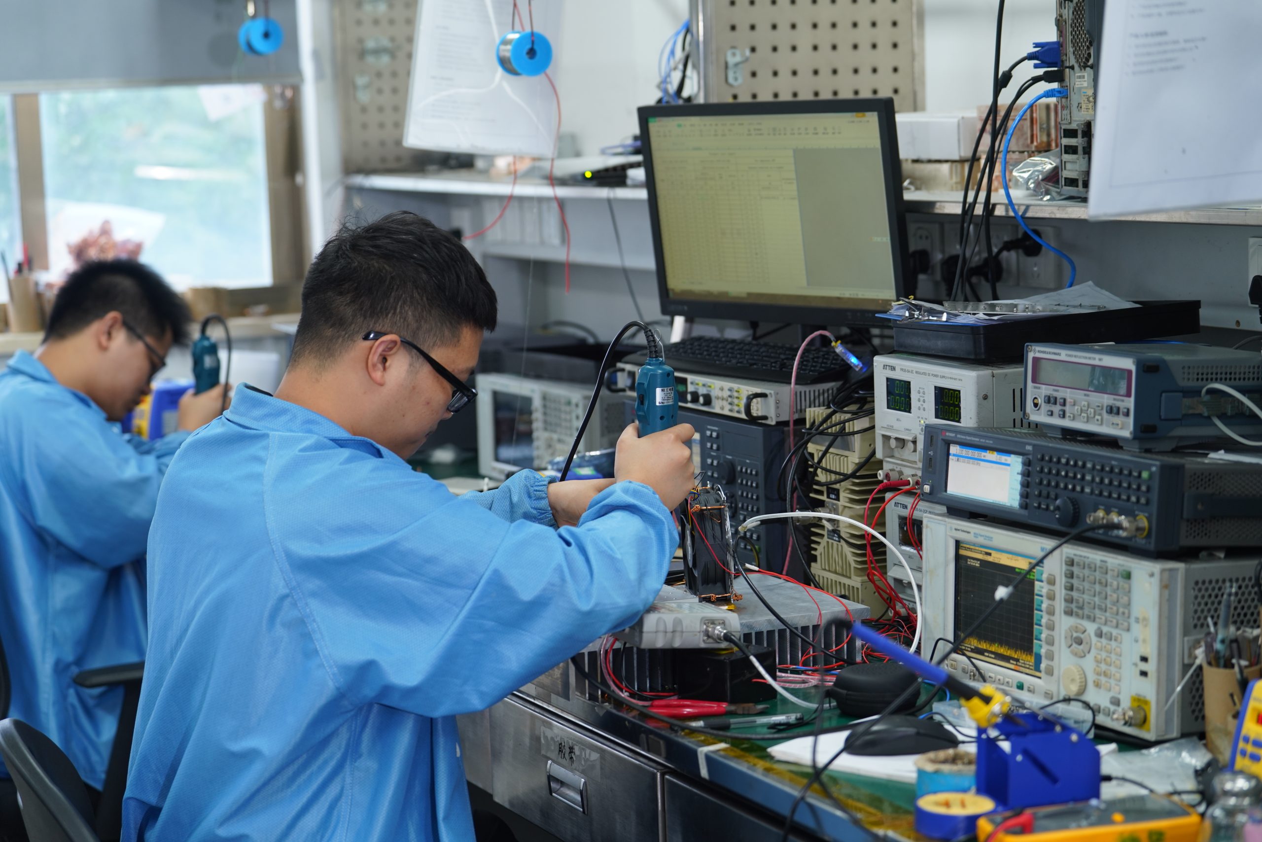
Our factory engineering workflow is designed to reduce mismatch early — from requirement review to model recommendation, technical confirmation, and production delivery support.
We begin by confirming frequency range, target output power, input drive level, supply voltage range, CW or pulse requirement, and any size, weight, or cooling constraints. These details are essential for accurate factory recommendation and avoid mismatched selections that surface later in the project.
We identify the most relevant standard amplifier platform by band, then narrow by output class, supply condition, and integration constraints. For projects outside the standard matrix, OEM/ODM customization is flagged early — with factory engineering review before commitment.
We review gain, flatness, stability, current demand, connector fit, cooling method, and protection expectations against the intended project conditions — including VSWR protection thresholds, DB9 control interface, over-temperature behavior, and thermal derating for the target environment.
You receive a recommended standard model path or a factory-customized direction — with datasheet, dimensional drawing, and factory test data to support internal review and sign-off before commitment.
Once direction is confirmed, you get quotation, prototype scheduling, or batch production follow-up — all managed factory direct. Lead time and delivery are confirmed based on your project timeline, with no middlemen between you and the manufacturing team.
Engineering FAQ for RF Amplifier Selection
Common questions engineering and procurement teams ask before amplifier platform selection, integration, and project commitment with a direct manufacturer.
Submit Your RF Amplifier Requirement to CorelixRF
Share your target frequency band, output level, supply condition, cooling preference, connector requirement, and project limits. CorelixRF will respond with a suitable standard platform recommendation or discuss a custom RF amplifier direction with factory engineering support.
Factory engineering review within 24–48 hours · Project details can be reviewed under NDA if required
Tell us your band, power, supply, cooling, and connector requirements — our factory engineering team responds within 24–48 hours. NDA available on request.