
Why Buyers Work with CorelixRF
We support RF integration projects that require engineering coordination, production consistency, and documented validation — not just a datasheet and a shipping label.
Engineering Coordination
Pre-quotation technical review covering operating mode, drive level, thermal budget, and system-level compatibility before production commitment.
Sub-Band Adaptation
Custom frequency optimization for narrower operating bands — improving gain flatness and efficiency within your specific transmit requirements.
Production Consistency
In-house RF assembly and machining under ISO 9001 process control. Unit-level validation data available with shipment, with documentation scope confirmed during technical intake.
Integration Support
Thermal interface guidance, mechanical drawing packages, and OEM/ODM feasibility assessment to reduce risk in enclosure and system-level integration.
Reducing Integration Uncertainty
Bridging the gap between headline specifications and real-world system-level requirements.
Common Challenges
Ambiguous Operating Definitions
Specifications often lack clarity around thermal limits, CW vs pulse operation, and duty cycle conditions — leading to mismatched expectations.
Missing Validation Data
Generic datasheets may not reflect actual shipped hardware performance across the full operating band, creating acceptance risk.
Thermal Integration Risk
Incomplete airflow planning, enclosure thermal path design, or mounting guidance can lead to failures during system-level qualification.
CorelixRF Approach
Validated Operating Modes
Operating conditions (CW/pulse, duty cycle, thermal limits) are defined and confirmed during engineering review — before quotation is issued.
Unit-Specific Test Records
Shipment test records — gain, output power, and input VSWR across the operating band — are available per project scope, supporting your incoming inspection workflow.
Thermal Interface Coordination
Mechanical outline drawings, connector references, and thermal integration guidance are provided to support airflow planning and enclosure integration.
Why This Platform Matters
Broadband coverage engineered without compromising thermal or electrical practicality.
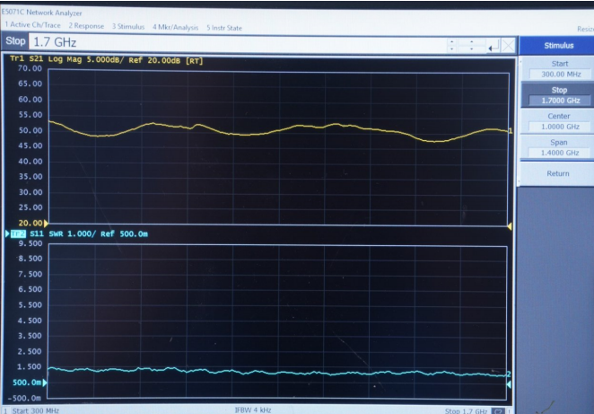
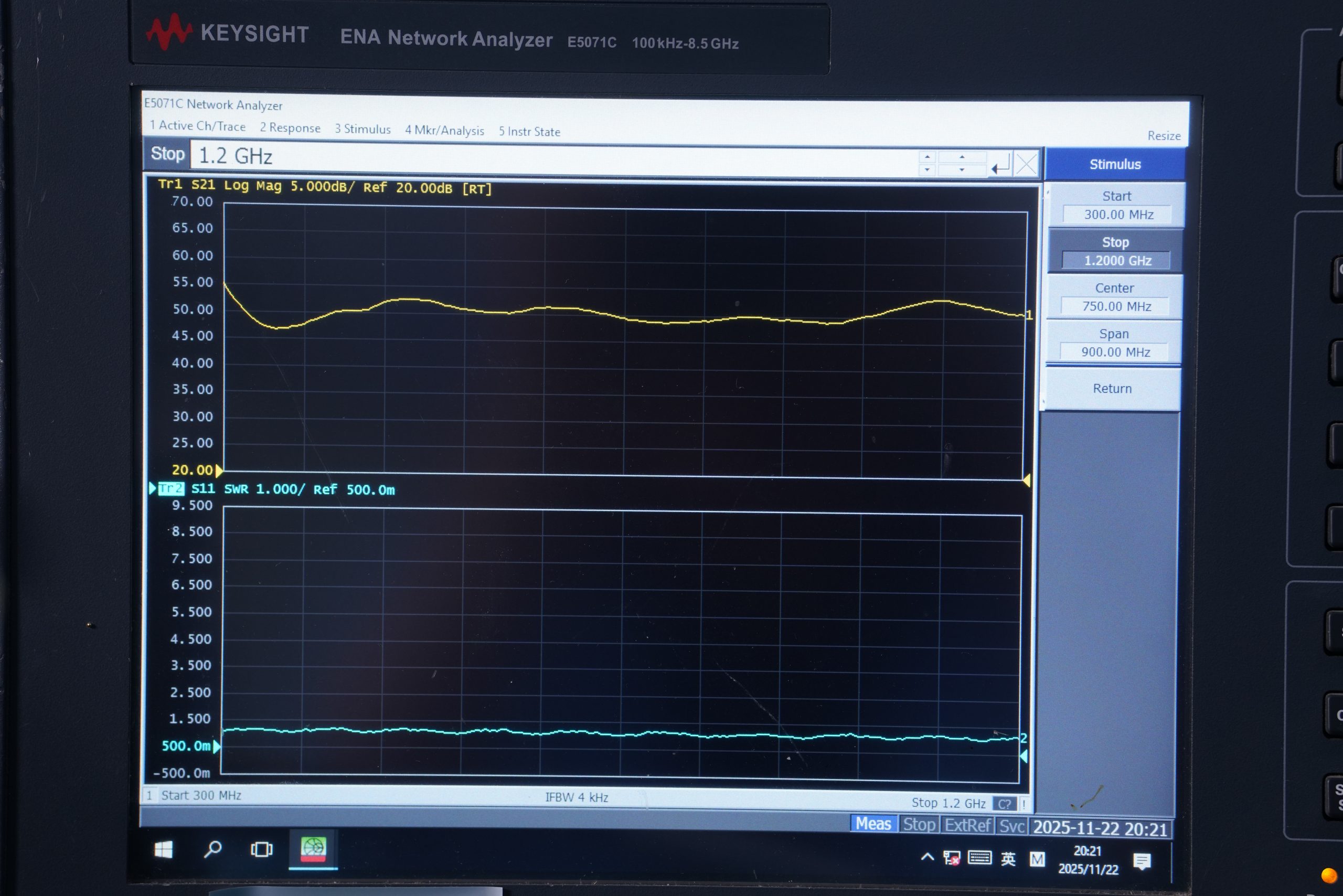
Wideband Consistency
Stable gain behavior across 300–1700 MHz simplifies transmit chain planning and reduces multi-band switching complexity.
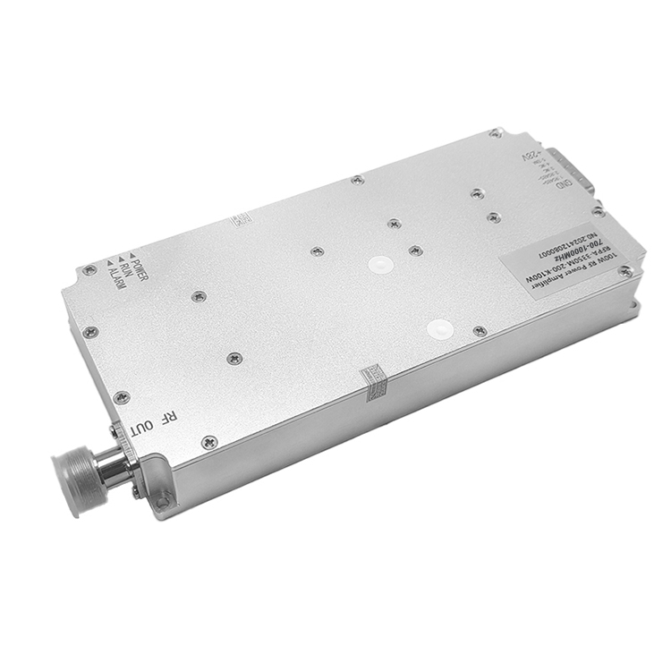
Platform Compatibility
Native 28VDC operation aligns with standard industrial and military power rails for straightforward system integration.
Thermal Path Integrity
Mechanical structure and mounting layout support practical thermal integration, with air-cooling requirements reviewed according to model power level and enclosure conditions.
Before You Order: Engineering Checklist
Confirm the following parameters before submitting your RFQ. This helps our engineering team provide an accurate technical assessment and quotation.
Standard Model Selection
Standard wideband models listed below. Custom frequency subsets available for improved flatness and efficiency on request.
| Model Number | Frequency | Pout | Gain | VSWR (In) | Supply | Size (mm) | |
|---|---|---|---|---|---|---|---|
| HZ3001700-30 | 300–1700 | 30W | 45 ± 1 dB | ≤1.8 | 28VDC | 125×59×21.5 | |
| HZ3001700-50 | 300–1700 | 50W | 47 ± 1 dB | ≤1.8 | 28VDC | 125×59×21.5 | |
| HZ3001700-100 Most Requested | 300–1700 | 100W | 50 ± 1 dB | ≤1.8 | 28VDC | 200×158×25 | |
| HZ3001700-150 | 300–1700 | 150W | 52 ± 1 dB | ≤1.8 | 28VDC | 200×158×25 | |
| HZ3001700-200 | 300–1700 | 200W | 53 ± 1 dB | ≤1.8 | 28VDC | 200×158×25 |
All documentation available upon request during engineering intake. Contact engineering →
Application Scenarios
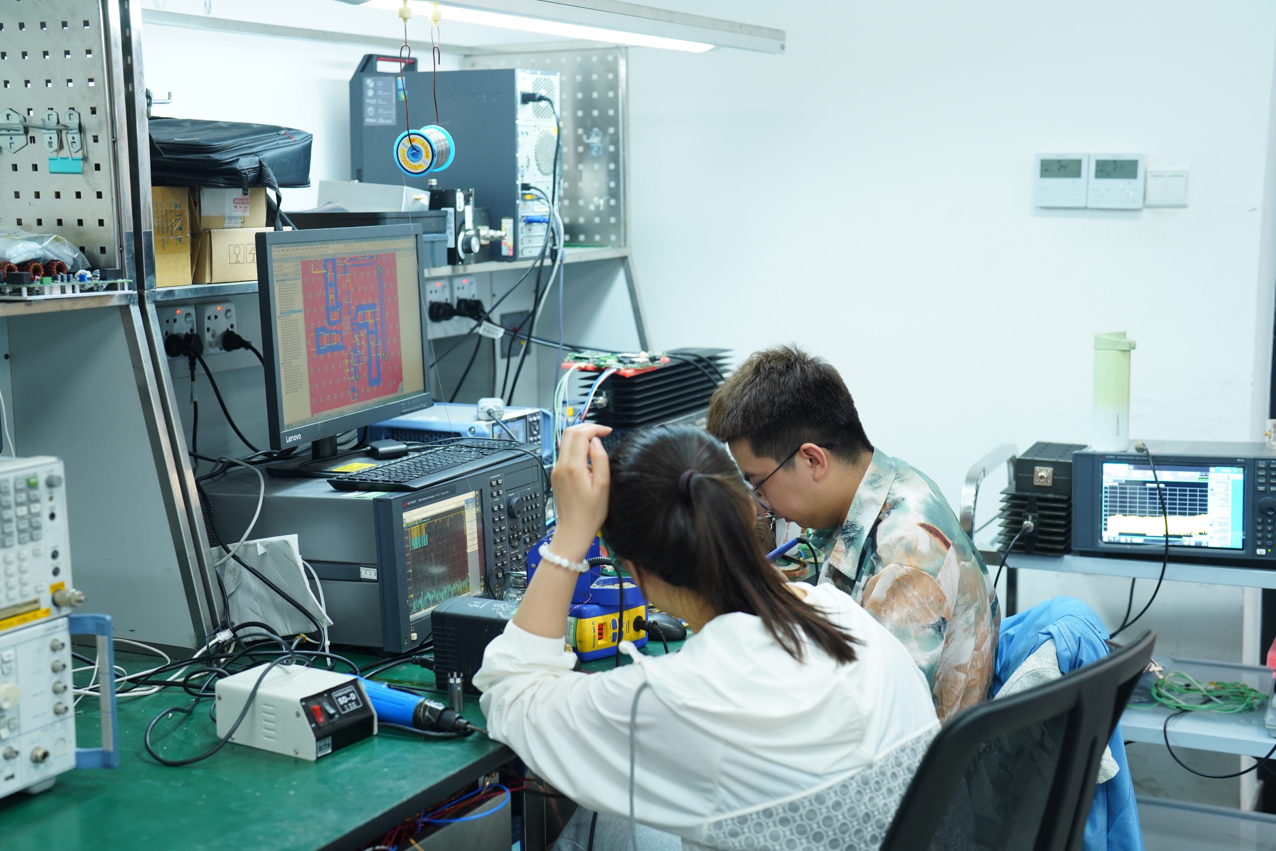
Manufacturing Evidence
In-house validation and assembly under ISO 9001 process control.
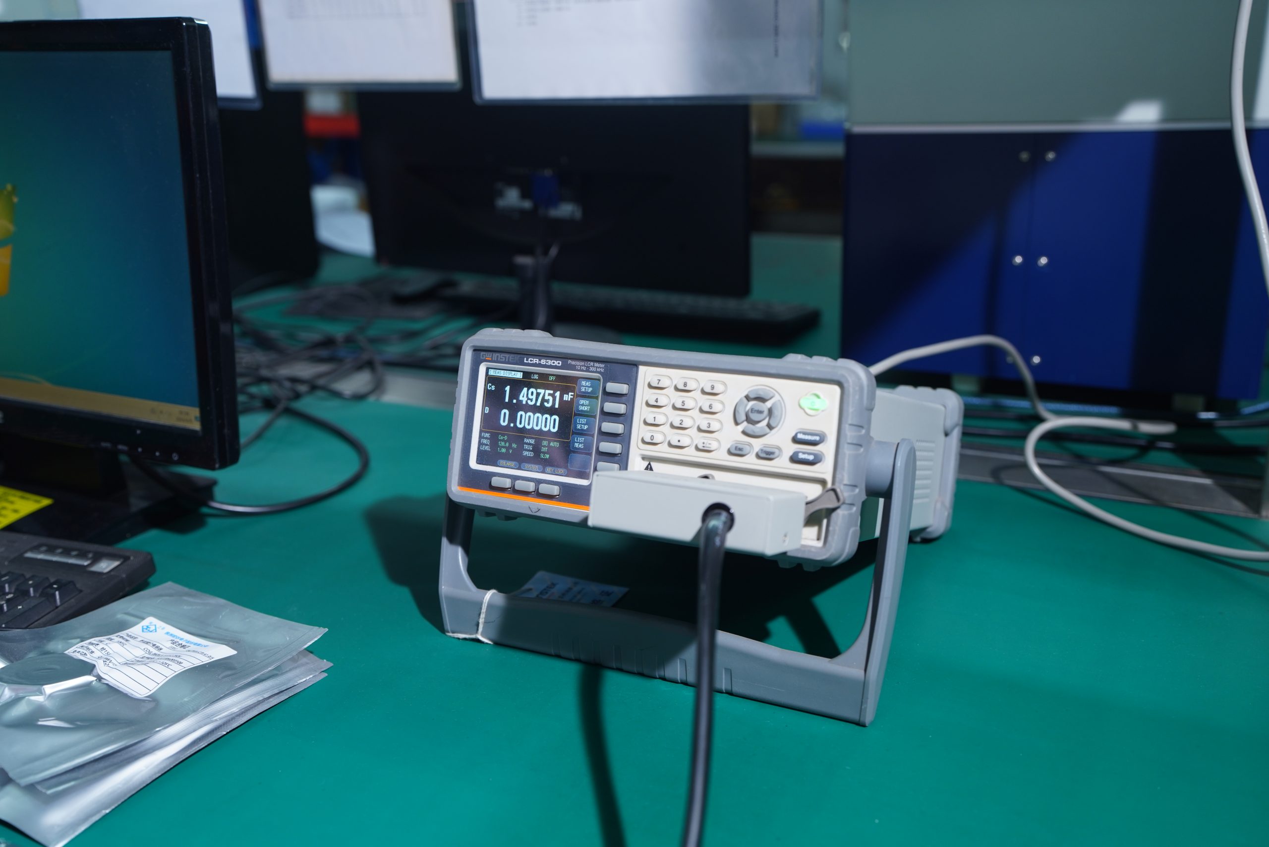
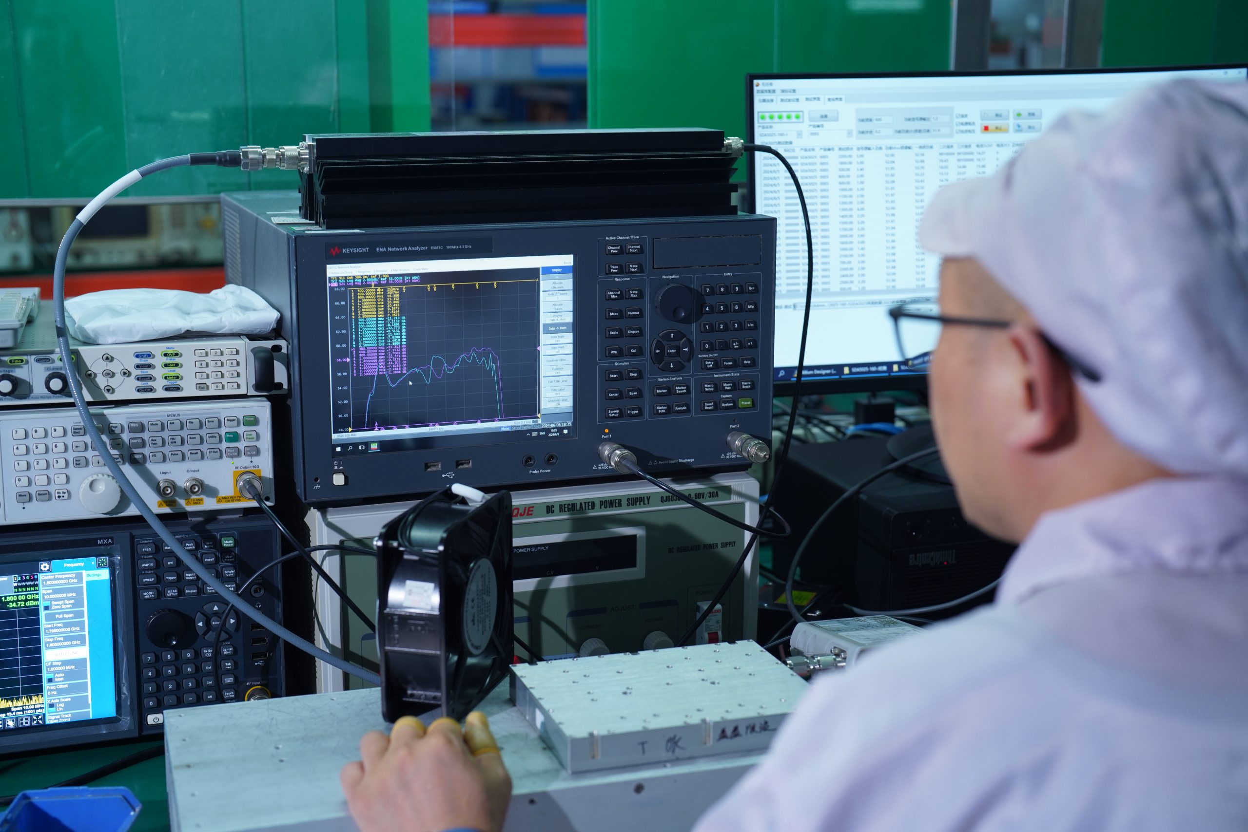
RF Validation
Full-band gain and power measurement on production units. Test report format available for incoming inspection review.
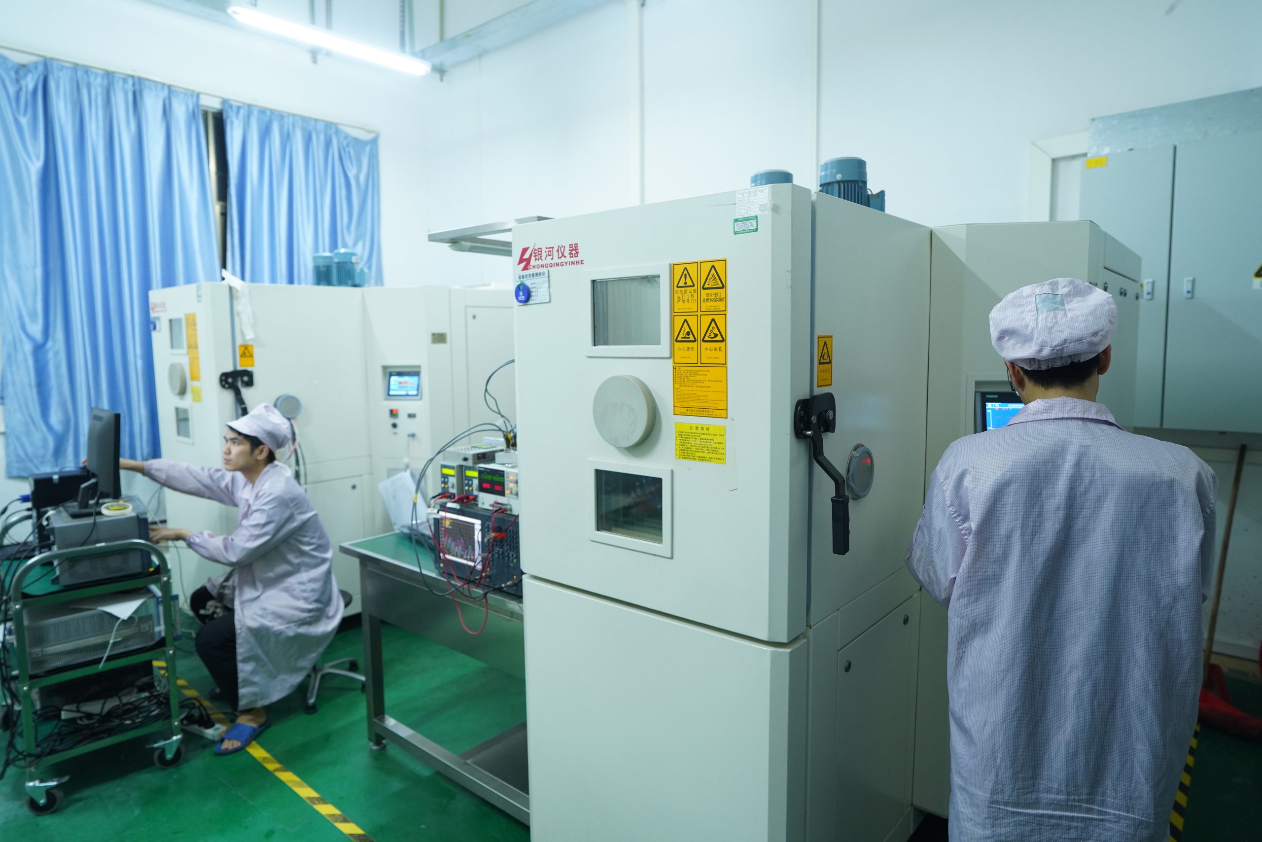
Thermal Screening
Operating stability validated under thermal load to confirm performance in real-world deployment environments.
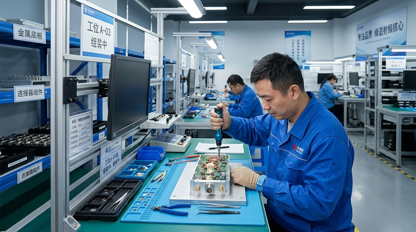
Internal Assembly
RF assembly, mechanical machining, and final integration performed in-house for production traceability.
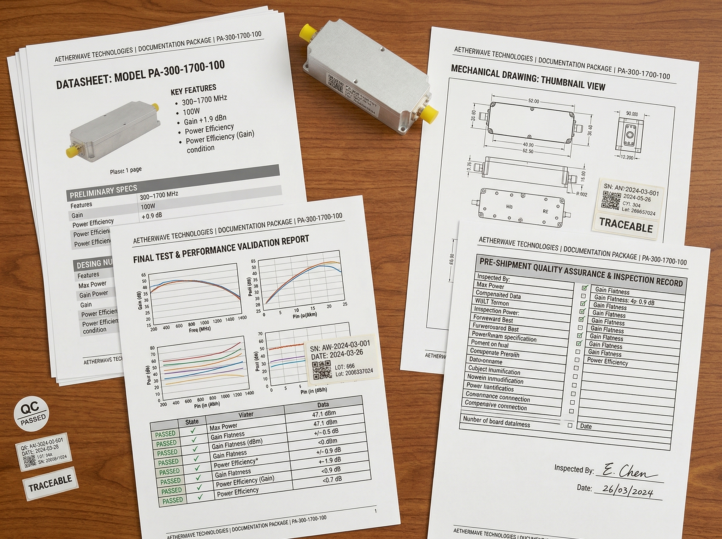
Quality Package
Shipment documentation scope — test reports, traceability records, and mechanical interface drawings — confirmed during engineering intake.
01 Technical FAQ
What input drive level is required?
Typical input drive for rated output is 0 to 8 dBm under datasheet test conditions. Specific drive margin should be confirmed per model and target operating condition.
Can the amplifier be optimized for a narrower frequency band?
Yes. Standard units cover 300–1700 MHz, and custom frequency subsets can be reviewed for flatter gain and better efficiency within your target operating range.
What PSU headroom is recommended?
We recommend 1.2× to 1.5× current headroom above maximum rated draw as an engineering recommendation, subject to operating mode and compression target. Specific current requirements are documented per model.
What cooling method is required?
Standard models in this series use air cooling. Mechanical outline, connector references, and integration dimensions are available in the drawing package. Airflow and enclosure thermal conditions can be reviewed during engineering assessment.
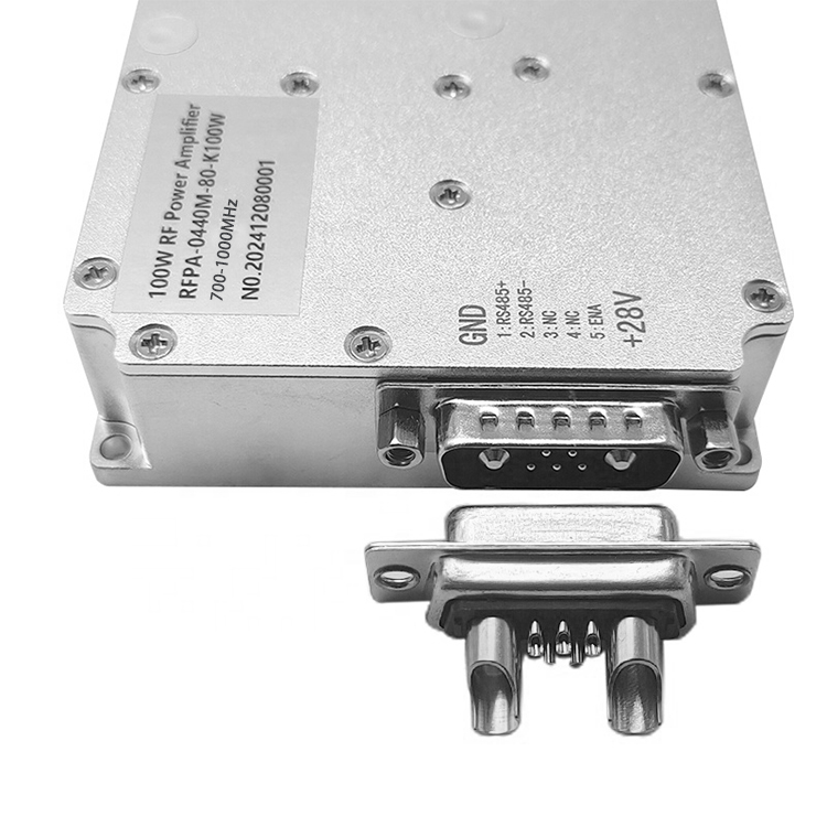
Are connector or mechanical modifications available?
Standard RF connectors are SMA-Female for input and N-Female for output. Alternative connector configurations and custom mounting details can be reviewed for OEM integration projects.
02 Procurement FAQ
What test data is included with shipment?
RF test data covering gain, output power, and input VSWR across the operating band is available with shipment. Sample report formats can be provided during the RFQ stage for your incoming inspection team to review. Documentation scope is confirmed during engineering intake.
Is evaluation unit support available?
Yes. We support evaluation quantities for engineering assessment and system-level qualification. Evaluation orders follow the same engineering review and validation process as production orders.
Is NDA support available for project discussion?
Yes. We can execute NDAs before technical deep-dives or sharing custom mechanical drawings, electrical integration data, or application-specific performance information.
What is the typical quotation workflow?
Submit an RFQ through our engineering intake form. Our team reviews your operating parameters, confirms technical feasibility, and provides a detailed quotation including lead time, documentation scope, and any customization requirements.
Request Technical Intake
Our engineering team reviews your project requirements — operating mode, frequency range, thermal constraints, and integration context — before issuing a quotation.
CorelixRF is a factory-direct RF manufacturer supplying amplifiers, antennas, SDR modules, and OEM RF subsystems for engineering-driven integration projects. We operate under ISO 9001 process control, with in-house RF assembly, mechanical machining, and unit-level validation.