
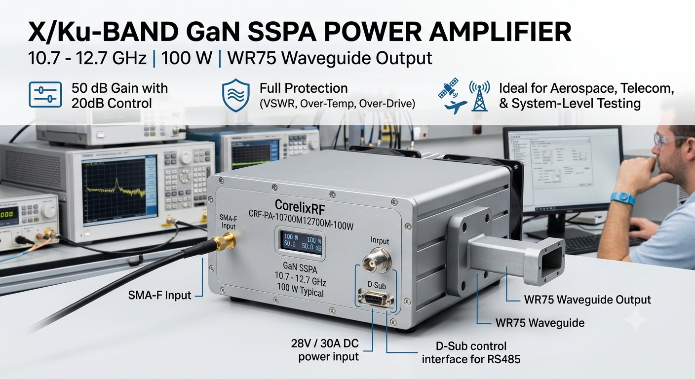
A 10.7-12.7 GHz 100W RF power amplifier is designed for engineers working in focused X/Ku-band RF systems. Compared with very wideband microwave amplifiers, this type of platform is selected when the project needs strong output power, defined frequency coverage, controlled gain, and a waveguide output interface.
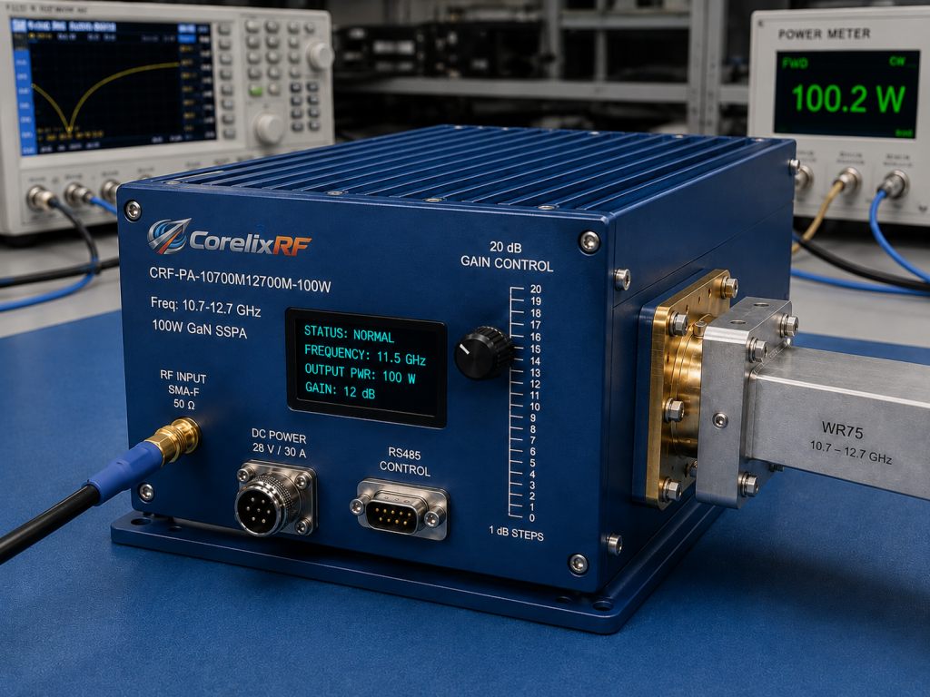
The CorelixRF CRF-PA-10700M12700M-100W operates from 10.7 GHz to 12.7 GHz with 100 W typical rated output power. It uses GaN SSPA technology, 50 dB minimum gain, ±2.5 dB typical gain flatness, 20 dB gain control in 1 dB steps, SMA-F input, WR75 output, RS485 control, and a 28 V / 30 A DC power supply.
Why This Band Needs a Purpose-Built Amplifier
Projects in the 10.7-12.7 GHz range often require predictable power delivery through a specific RF chain. The WR75 output interface makes the amplifier suitable for systems where waveguide output is preferred over coaxial output at these frequencies. Engineers should confirm the downstream waveguide, adapter plan, antenna interface, and measurement method before final acceptance testing.
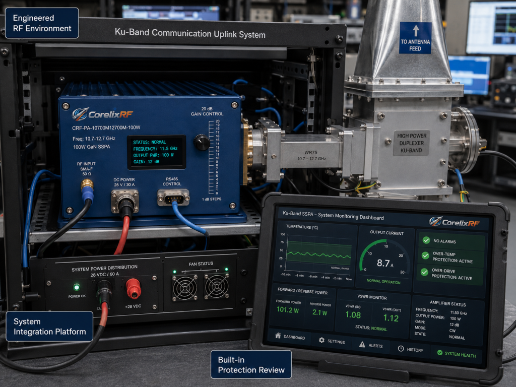
The amplifier is intended for test and measurement instrumentation, communication systems, RF interference system-level testing, and aerospace control systems. It can be reviewed for laboratory systems, integration platforms, and other engineered RF environments where a custom RF amplifier review is needed.
Gain Control and Output Stability
The CRF-PA-10700M12700M-100W provides 50 dB minimum gain and 20 dB gain control in 1 dB steps. This is useful when engineers need to adjust output power without changing the RF source level or external attenuator chain.
Gain flatness is listed at ±2.5 dB typical. In a focused-band amplifier, flatter gain can help simplify calibration and maintain more consistent output across the operating band. Engineers should still request final production test data for the specific configuration and acceptance conditions.
Interface, Cooling, and Power Supply Review
The listed RF interfaces are SMA-F input and WR75 output. The control interface is RS485. The power supply is specified as 28 V / 30 A DC. The source data notes that mechanical size is project-dependent and that system-level forced-air cooling is required.
Because the mechanical form factor is marked as TBD in the source data, integrators should discuss enclosure size, mounting, airflow, connector orientation, and cable or waveguide routing early. A clear mechanical review reduces the risk of late-stage redesign.
Protection and Monitoring Requirements
The amplifier includes real-time temperature monitoring, real-time current monitoring, alarm and fault protection, over-temperature protection, over-drive protection, over-voltage protection, and VSWR protection. Optional forward and reverse power monitoring can be reviewed based on project requirements.
These features help protect the GaN RF amplifier during real system operation. At Ku-band frequencies, load changes, adapters, waveguide transitions, and antenna mismatch can all influence reflected power. Protection functions and monitoring should be included in the acceptance plan.
Information to Provide Before Quotation
To evaluate fit, provide the exact operating frequency, required output power, waveform, duty cycle, gain control needs, source input level, cooling environment, output interface, control interface, and mechanical constraints. If the amplifier will be used in a rack, enclosure, or system-level platform, include airflow and mounting details.
The 10.7-12.7 GHz 100 W RF power amplifier platform is best suited for projects that need a defined X/Ku-band operating range, waveguide output, controllable gain, and built-in protection for system integration.
FAQ
What is the focus keyword?
The focus keyword is 10.7-12.7 GHz 100W RF power amplifier.
What is the output interface?
The listed output interface is WR75.
Does the amplifier support gain control?
Yes. The source data lists 20 dB gain control in 1 dB steps.
X/Ku-Band Amplifier Buying Path
For X/Ku-band test benches and links, compare this unit against the broader RF power amplifier range, define any custom RF amplifier interface needs, and confirm drive-level compatibility with the signal source.