
A 1170-1280 MHz 200W narrowband RF amplifier is selected when the project benefits from a focused RF power stage instead of a wider broadband amplifier. Narrowband selection can improve fit when the operating band, output target, mechanical envelope, heat-sink plan, and control logic are already known. It also helps buyers avoid paying for bandwidth they do not need.
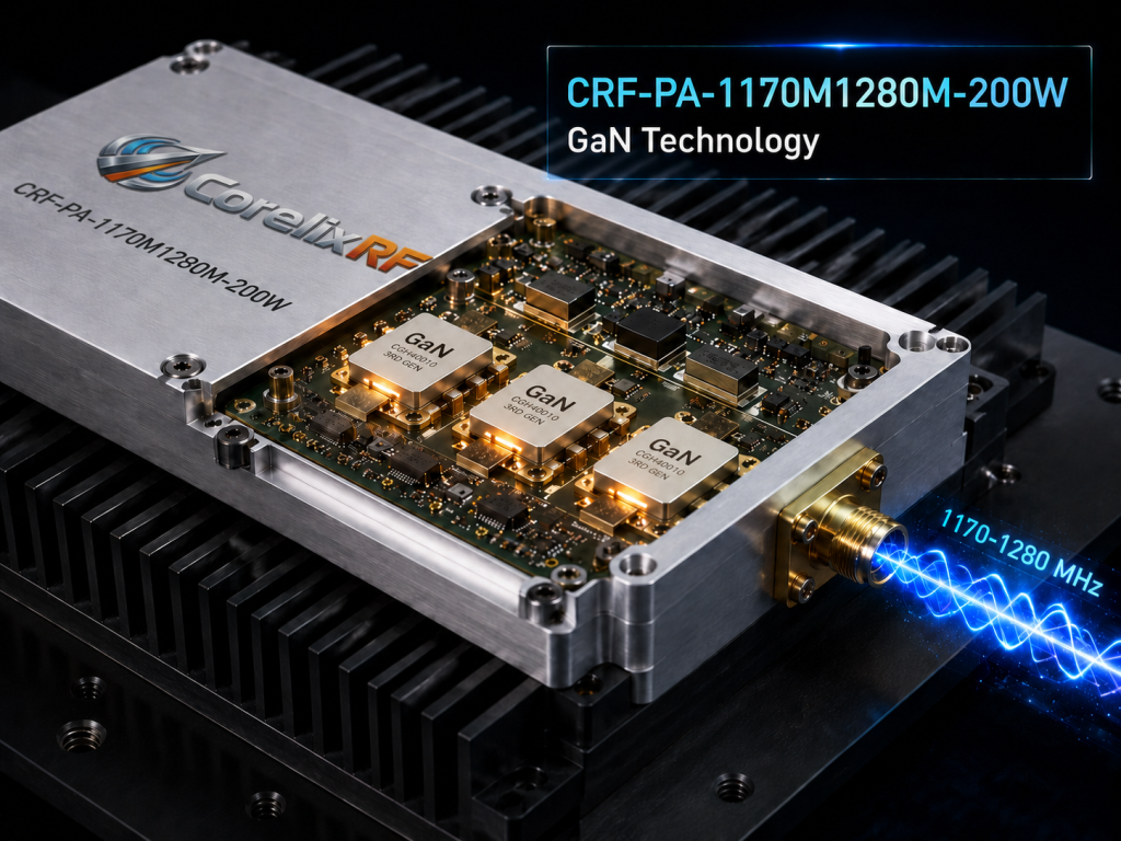
CorelixRF CRF-PA-1170M1280M-200W is specified for 1170 MHz to 1280 MHz operation with 200 W rated CW output power, third-generation GaN transistors, 49 dB minimum gain, 51 dB typical gain, and 53 dB maximum gain. The source data lists M and V versions, where the V version includes an internal VCO source with 10 Hz stepping. The product direction belongs in CorelixRF’s narrowband amplifier selection path.
Why Use a Narrowband RF Amplifier Instead of a Broadband Model
Broadband amplifiers are useful when the required band is not fixed or when one test bench must cover many programs. A narrowband amplifier makes more sense when the project is centered on a defined frequency window and needs a compact, application-specific hardware path. The 1170-1280 MHz span is narrow enough that gain control, mechanical package, VCO option, and protection logic can be reviewed around the actual use case.
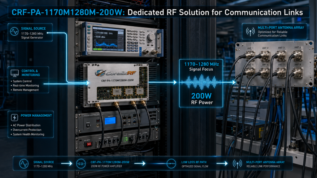
For communication systems, RF test platforms, and project-specific RF source integration, that focus can reduce ambiguity. The engineer can review the amplifier around a known link budget, source level, heat sink, connector layout, and enable/disable timing instead of treating it as a general-purpose lab amplifier.
Key Parameters for CRF-PA-1170M1280M-200W
The source specification lists 1170-1280 MHz frequency coverage and 200 W rated CW output power. Output power is shown as 160 W minimum and 200 W typical under the stated conditions. Gain is listed as 49 dB minimum, 51 dB typical, and 53 dB maximum. Gain adjustment range is 20 dB, with 0.5 dB steps.
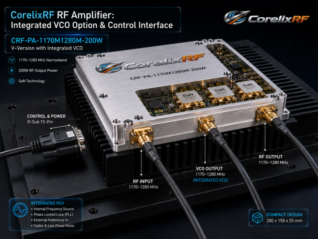
The amplifier operates from +24 V to +32 V, with +28 V nominal supply. Typical current is 30 A and maximum current is 36 A. PA enable/disable time is listed as 100 microseconds maximum. RF connectors are SMA-KFD46, while control and power references include a D-Sub 15-pin female connector and pull-core capacitance power input. Mechanical size is 200 x 158 x 25 mm, with 1.4 kg weight and external heat sink cooling.
M Version and V Version Considerations
The source material describes an M version without internal VCO and a V version with internal VCO source and scan function. The V version lists 10 Hz frequency stepping and a frequency/bandwidth adjustment range reference of 920/50 to 1300/380 MHz. The correct version depends on whether the system already has a signal source or needs an integrated source path.
If the project already has an SDR, synthesizer, or signal generator, the M version may be the simpler amplifier module path. If the project needs the amplifier and source function integrated in a tighter subsystem, the V version should be discussed. For projects involving signal-chain design, CorelixRF’s broader RF amplifier and SDR-related pages can provide a better starting context.
Protection and Control Features
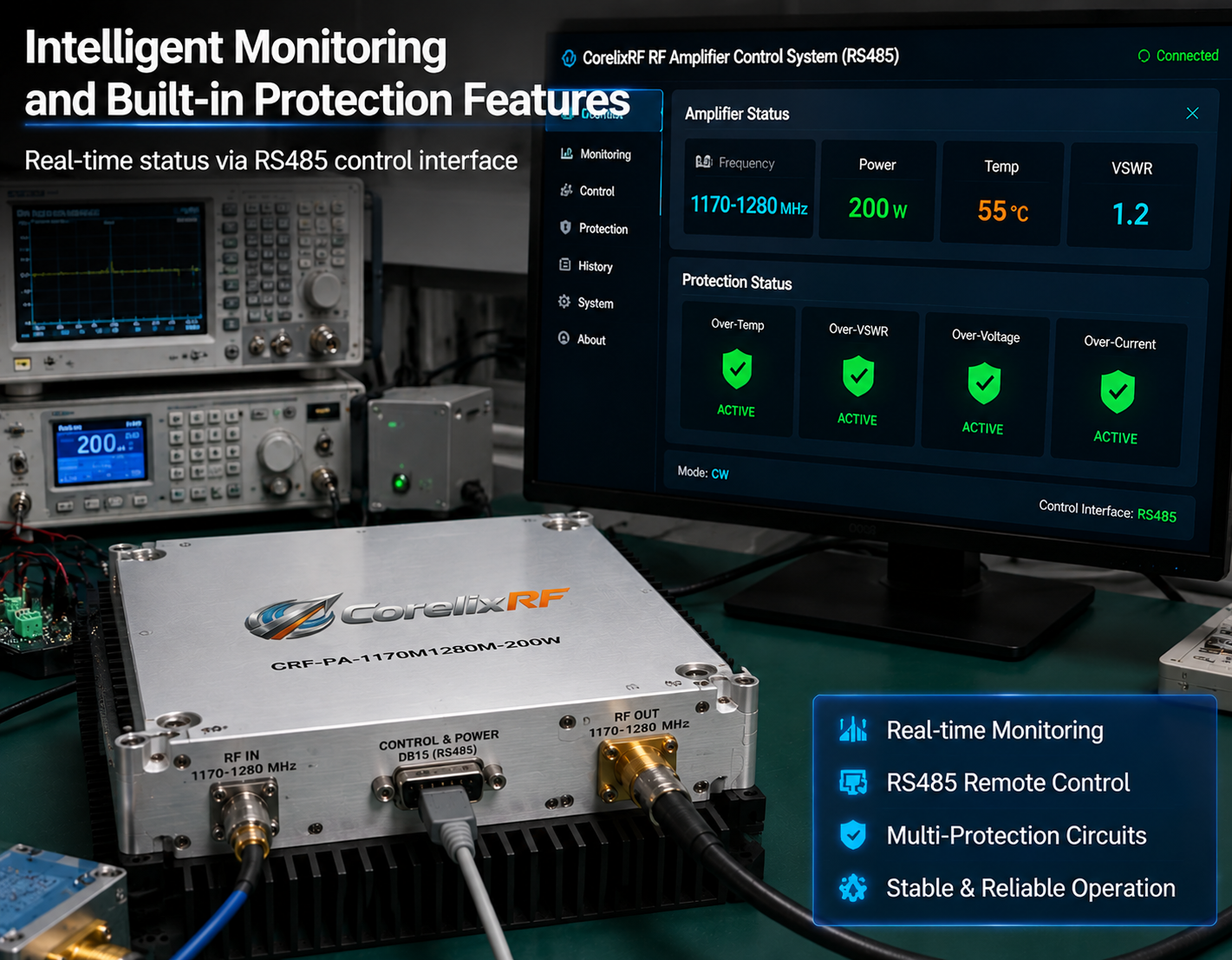
The source specification lists optional RS485 monitoring/control, Pf/Pr power indicators from 0-3 V, temperature analog output, PA enable/disable control, alarm reset support, and gain/power adjustment where applicable. Built-in protection includes over-temperature shutdown/recovery, over-VSWR locked shutdown, over-voltage lock above 32 V, and over-current lock above 38 A.
These details matter because narrowband modules are often embedded in systems where the heat sink, airflow, control wiring, and fault response are defined by the larger assembly. A custom RF amplifier review should therefore include the mechanical drawing, thermal interface, connector orientation, and control logic rather than only frequency and output power.
Application Fit and RFQ Guidance
This platform fits narrowband RF amplification, communication systems, RF test and measurement, and system-level RF source integration. It may be appropriate where a 1170-1280 MHz high-power stage must fit a compact mechanical envelope with external heat sinking and defined control I/O.
For an RFQ, provide the exact center frequency or channel plan, required output power, waveform, duty cycle, source level, M or V version preference, heat-sink conditions, supply range, control interface, alarm handling, connector requirements, and environmental constraints. Use the Contact CorelixRF page when the version choice or thermal design needs engineering review.
FAQ
What frequency range does CRF-PA-1170M1280M-200W cover?
The source specification lists 1170 MHz to 1280 MHz.
What output power is listed?
The datasheet states 200 W rated CW output power, with 160 W minimum and 200 W typical under stated conditions.
What is the difference between M and V versions?
The M version is an amplifier module path, while the V version includes an internal VCO source and scan-related function.
What cooling method is required?
The source material lists external heat sink cooling, so thermal interface design must be reviewed during integration.
CTA: Contact CorelixRF