
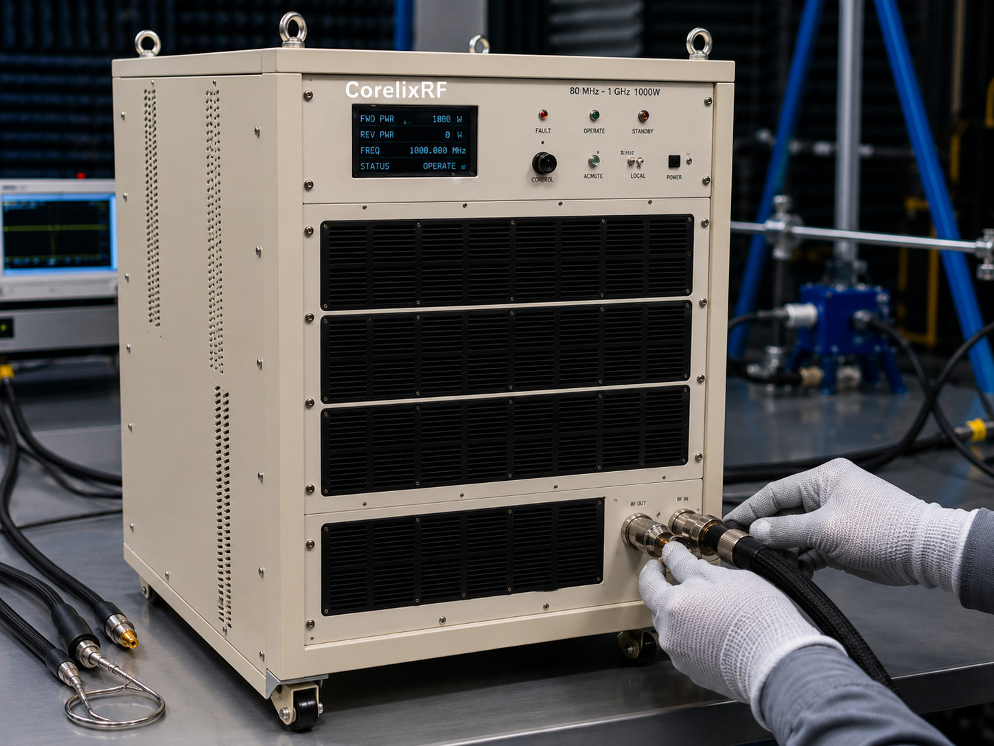
An 80 MHz-1 GHz 1000W EMC RF amplifier is chosen when a lab or system integrator needs high RF output power across VHF/UHF and low microwave-adjacent ranges without switching between many narrow amplifiers. This coverage can support immunity-oriented laboratory work, communication-system evaluation, interference path studies, and other high-power RF validation tasks where the load path and protection strategy need careful review.
CorelixRF CRF-PA-80M1000M-1000W is specified as an LDMOS solid-state RF power amplifier covering 80 MHz to 1 GHz with 1000 W minimum RF output power and 60 dB minimum small-signal gain. It lists N-female input, 7/16-female rear-panel output, RS485/LAN control, AC 380 V power, air cooling, and optional forward/reverse power monitoring. For general platform orientation, CorelixRF’s RF power amplifier page identifies EMC, pulsed, high-power, and custom amplifier paths as project-based categories.
Why 80 MHz-1 GHz Coverage Matters in EMC and RF Labs
The 80 MHz to 1 GHz range overlaps many practical VHF and UHF test scenarios. A single UHF power amplifier path can reduce reconfiguration when a lab needs broad coverage, especially when the same test room, antenna, coupler, or load infrastructure must support multiple frequency points.
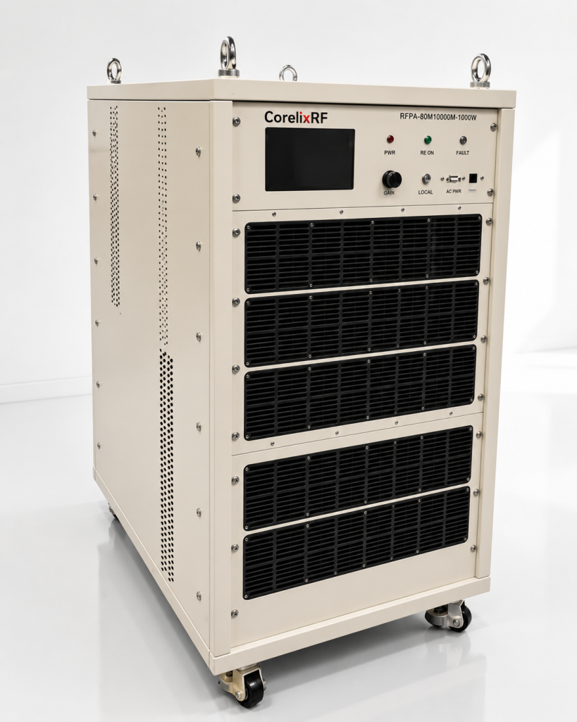
At 1000 W, the amplifier must be matched to the test setup, not selected only by frequency and output power. Cable losses, antenna gain, field uniformity goals, coupler ratings, attenuator ratings, room constraints, and load mismatch must be reviewed. For EMC-style work, the final power required at the amplifier output depends on the test distance, antenna factor, modulation, standard or internal procedure, and margin strategy.
Source Specifications for CRF-PA-80M1000M-1000W
The source datasheet lists 80 MHz to 1 GHz frequency coverage, 1000 W minimum output power, and 60 dB minimum small-signal gain. Gain flatness is specified as -5 to +5 dB, with up to 20 dB gain control range. Maximum input power is listed as 0 dBm, input impedance is 50 ohms, and VSWR is listed as 1.5:1 typical.
The RF input connector is N-female on the rear panel, while the RF output connector is 7/16-female on the rear panel. The listed control interfaces are RS485 and LAN. The power supply is AC 380 V +/-10%, 50/60 Hz. Mechanical size is marked TBD in the source material, so buyers should request the final outline drawing before committing rack space, floor space, or transport planning.
Protection Features for High-Power Low-Band RF
The source specification lists real-time temperature monitoring, real-time current monitoring, optional forward/reverse power monitoring, optional LAN remote monitoring, alarm and fault protection, over-temperature protection, over-voltage protection, and VSWR protection/alarm functions. These features are useful when the amplifier is connected to changing antenna, load, or chamber configurations.
A 1000 W EMC RF amplifier should be reviewed with the full load path. Protection features help, but they do not replace proper coupler selection, antenna rating, load rating, cable inspection, and operating procedures. Reflected power and overheating risks are most easily controlled when the amplifier, antenna, room layout, and duty profile are reviewed together.
When to Choose This Platform
This amplifier is relevant when the project needs high RF power across 80 MHz-1 GHz, especially where LDMOS technology is appropriate for lower-frequency high-power operation. Typical stated application areas include test and measurement instrumentation, communication systems, RF interference or EW system-level testing, and aerospace control systems.
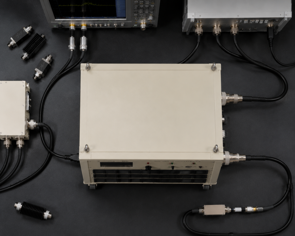
If the project is below 512 MHz or has a narrower VHF/UHF requirement, CorelixRF’s UHF / specialized amplifier path may provide a better initial comparison. If the project must combine amplifier, antenna, control interface, enclosure, or documentation requirements, the Contact CorelixRF page is the correct internal CTA for review.
RFQ Checklist for an 80 MHz-1 GHz 1000W Amplifier
Include the exact operating band, required field or output power target, test distance if applicable, antenna type, load VSWR, modulation, duty cycle, input drive, control interface, AC power availability, cooling environment, and any test-data documentation needs. If mechanical data is required for approval, request final drawings because the source specification lists the mechanical form factor as TBD.
Also define whether the amplifier will be used for continuous operation, stepped frequency testing, sweep testing, or short-duration system evaluation. These use cases can create very different thermal and control requirements even when the headline frequency and output power are identical.
FAQ
What is the frequency range of CRF-PA-80M1000M-1000W?
The source specification lists 80 MHz to 1 GHz.
Is this amplifier GaN or LDMOS?
The source material describes it as an LDMOS SSPA platform.
What RF output connector is listed?
The listed RF output connector is 7/16-female on the rear panel.
Why is final mechanical review necessary?
The source specification marks mechanical size as TBD, so final drawings should be requested before installation planning.