
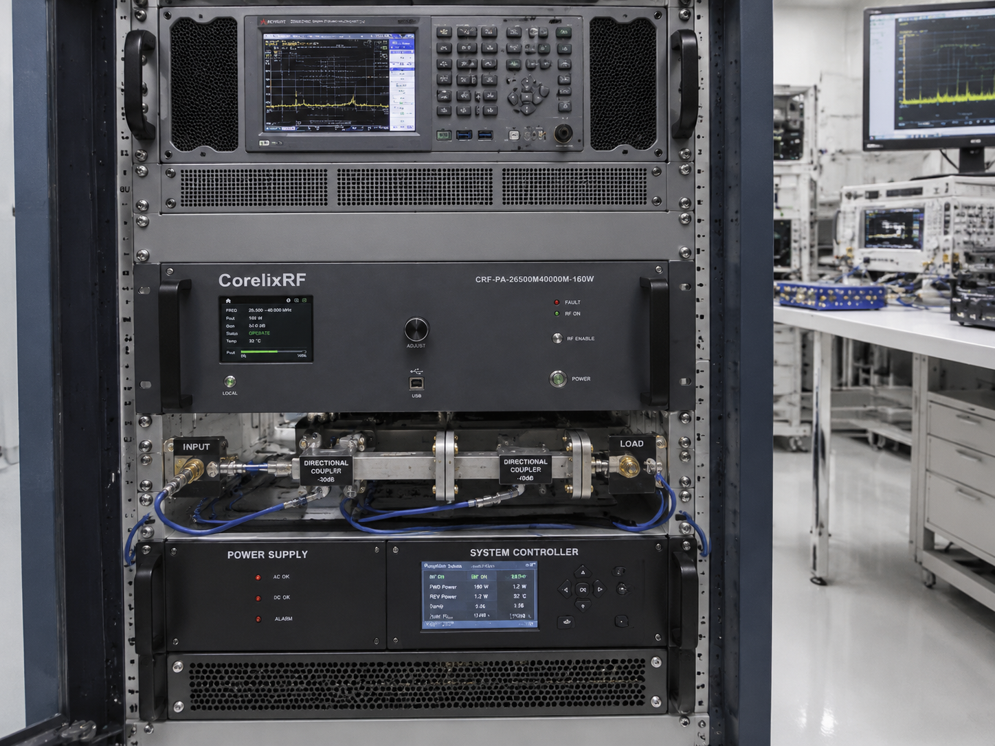
A 26.5-40 GHz 160W RF amplifier is a Ka-band power platform for laboratories and system teams that need meaningful output power at microwave frequencies where connector path, cooling, gain flatness, and control telemetry are difficult to treat as afterthoughts. The higher the frequency and power level, the more the amplifier becomes an integration project rather than a simple component purchase.
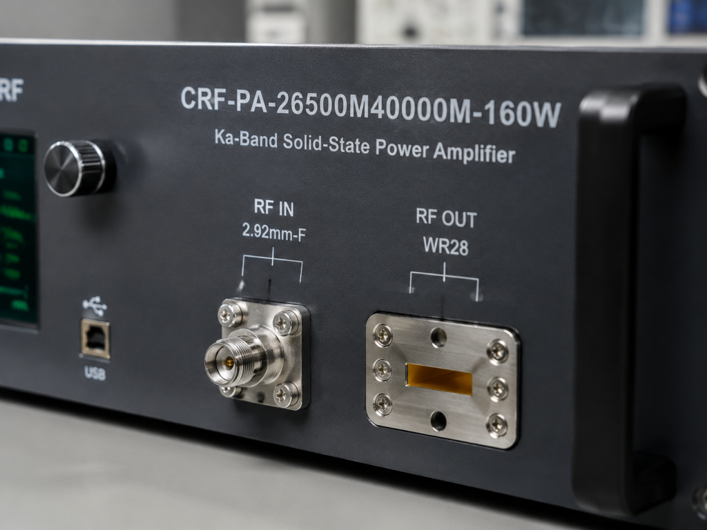
CorelixRF CRF-PA-26500M40000M-160W is specified for 26.5 GHz to 40 GHz operation with 160 W rated solid-state output power. The datasheet lists 52 dB minimum small-signal gain, 2.92 mm female RF input, WR28 RF output, RS485/LAN control, AC 380 V power, forced-air cooling, and a 19-inch 8U rack-mount mechanical format. It belongs naturally in the 18-40 GHz amplifier selection path because that page is CorelixRF’s online entry point for Ka-band review.
Why Ka-Band RF Amplifier Selection Needs Early Interface Review
At 26.5-40 GHz, a small mechanical decision can affect the RF result. Connector launch, waveguide transition, cable length, adapter quality, bend radius, and output load condition all matter. This is why the CRF-PA-26500M40000M-160W uses a 2.92 mm female input and WR28 output. The input side matches the microwave signal source path, while the output side supports waveguide delivery at the power level and frequency range.
The amplifier’s 19-inch 8U rack-mount format also changes installation planning. Teams should reserve rack space, airflow clearance, AC power, cable routing, waveguide routing, and safe access to the output path. The source specification lists typical weight of 70 kg, so handling and cabinet support should be reviewed before procurement.
Key Parameters for CRF-PA-26500M40000M-160W
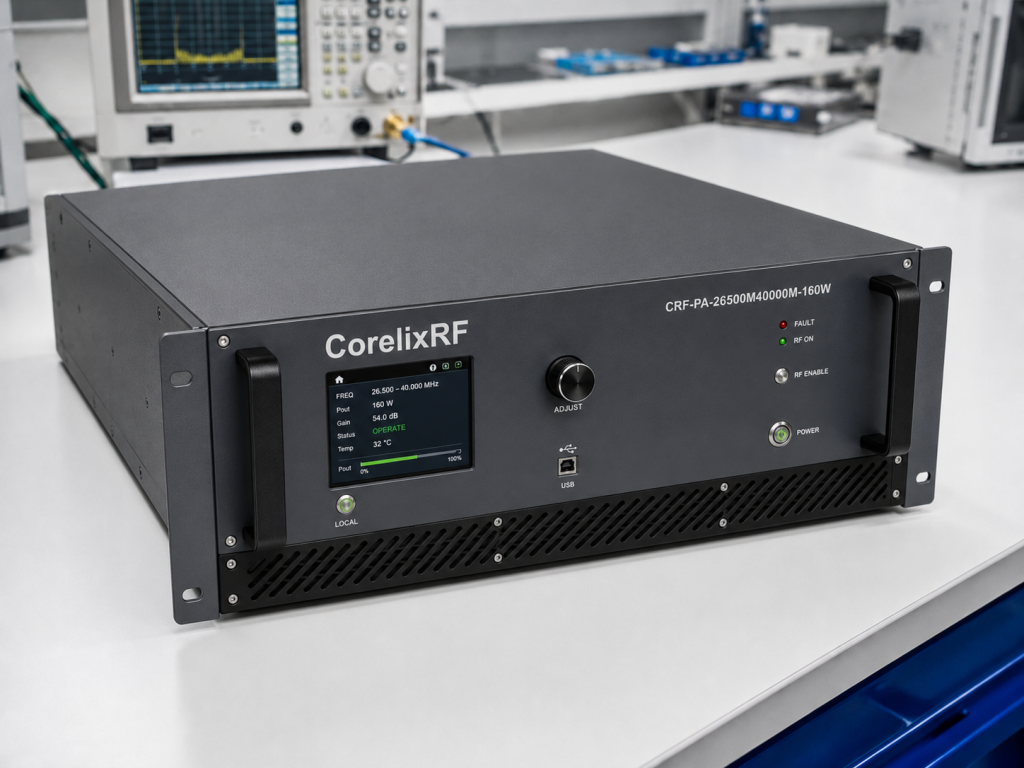
The model covers 26.5-40 GHz and provides 160 W rated RF output power. Minimum gain is 52 dB, with gain flatness of -8 to +8 dB and up to 15 dB gain control range. Maximum input power is listed as 3 dBm. Spurious performance is listed at -60 dBc maximum, while harmonics are listed at -10 dBc maximum.
Power consumption is 3600 W typical, with AC 380 V +/-10%, 50/60 Hz. Cooling is forced air, and the listed operating temperature range is 0 to +50 degrees C. These details should appear in the purchasing and installation checklist; they are not minor notes once the amplifier is installed in a test rack.
Protection and Monitoring in a 26.5-40 GHz Amplifier
The source data lists real-time temperature monitoring, real-time current monitoring, optional forward/reverse power monitoring, optional LAN remote monitoring, alarm/fault protection, over-temperature protection, over-drive protection, over-voltage protection, and VSWR protection/alarm functions. For a microwave amplifier in this power class, these monitoring points help engineers diagnose load-path problems before they become repeated test failures.
Reflected power is especially important in waveguide systems. Adapters, fixtures, antennas, or device-under-test ports may not present a stable load across the whole Ka-band range. The amplifier should therefore be reviewed with the intended waveguide components, directional couplers, isolators where applicable, and measurement plan.
Application Fit
This platform is relevant for test and measurement instrumentation, communication systems, RF interference or EW system-level testing, and aerospace-control related RF projects. It may also support high-frequency module testing and front-end evaluation where the required power level exceeds driver amplifiers.
The CorelixRF high-frequency amplifier path is useful when project teams need to compare Ka-band requirements against broader 6-40 GHz platform choices. If the exact band, output power, connector path, or control logic is not settled, the safer route is to provide a complete requirement package through Contact CorelixRF and request engineering feedback.
What to Include in a Ka-Band RFQ
A good RFQ should include frequency range, required output power at the load, waveform and duty profile, input drive available, waveguide or coaxial output preference, expected load VSWR, operating temperature, rack space, cooling airflow, remote-control method, and whether forward/reverse power monitoring is required.
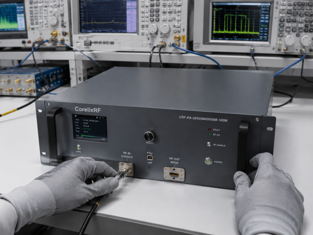
Also provide the system diagram if available. A simple block diagram showing signal source, pre-driver, amplifier, waveguide path, switches, couplers, load, antenna, or device under test can shorten the review cycle. CorelixRF’s RF testing and validation content path is relevant when documentation and measured data are part of the buyer’s approval process.
FAQ
What frequency range does this Ka-band RF amplifier cover?
CRF-PA-26500M40000M-160W is specified for 26.5 GHz to 40 GHz.
What output connector is listed?
The source specification lists WR28 RF output and 2.92 mm female RF input.
Is this a rack-mount amplifier?
Yes. The listed mechanical form factor is 19-inch 8U rack-mount.
Why is gain flatness important at 26.5-40 GHz?
Gain flatness affects how much drive-level compensation may be needed across the sweep range.