
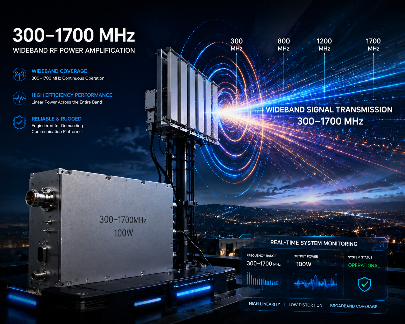
The CRF-PA-300M1700M-100W RF amplifier is a useful starting point for teams that need a 300-1700 MHz broadband RF power stage without immediately moving into a larger rack-level system. It sits in a frequency range that can support wideband RF transmit chains, RF test systems, communication platforms, C-UAS chain evaluation, antenna testing, and OEM integration where 300 MHz to 1700 MHz coverage is more appropriate than a wider 300-2700 MHz platform.
CorelixRF lists the 300-1700 MHz RF power amplifier family as a factory-direct 30 W to 200 W broadband module series. The public model table identifies CRF-PA-300M1700M-100W as a 300-1700 MHz, 100 W model with 50 dB typical gain, input VSWR of 1.8:1 or better, 28 VDC supply, and a 200 x 158 x 25 mm size. The page also references SMA-F input, N-F output, air cooling, model-specific datasheets, test curves, mechanical drawings, and unit-level validation data after engineering review.
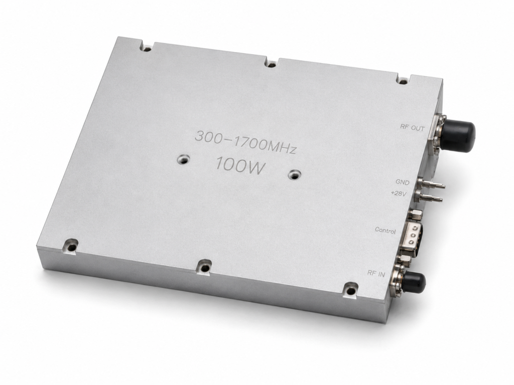
Why the 100W model is a practical midpoint
The 100 W output class is often a useful midpoint between compact lab modules and higher-power transmit-chain amplifiers. A 30 W or 50 W model may fit a driver-stage or evaluation bench, while a 150 W or 200 W model may be selected for demanding output paths. The CRF-PA-300M1700M-100W gives engineers a standard power class for OEM systems where output power, size, and thermal review must stay balanced.
For procurement, the key question is not simply whether the label says 100 W. The buyer should define where power is needed: at the amplifier output, after a cable, through a switch matrix, at an antenna feed, or at a device under test. Cable loss, filter loss, couplers, adapters, and mismatch can change the real delivered power.
Match 300-1700 MHz coverage to the system band
A 300-1700 MHz RF power amplifier can fit many projects, but not all of them need full-band operation. Some systems need only a lower UHF or L-band subset. Others require continuous coverage for evaluation, signal generation, or multi-band testing.
During RFQ review, specify whether full 300-1700 MHz coverage is required or whether a narrower sub-band can be optimized. CorelixRF notes that custom frequency subsets can be reviewed for flatter gain or improved efficiency within the target band. This is important for OEM buyers because the best technical route may be a standard model, a sub-band review, or a modified mechanical/interface configuration.
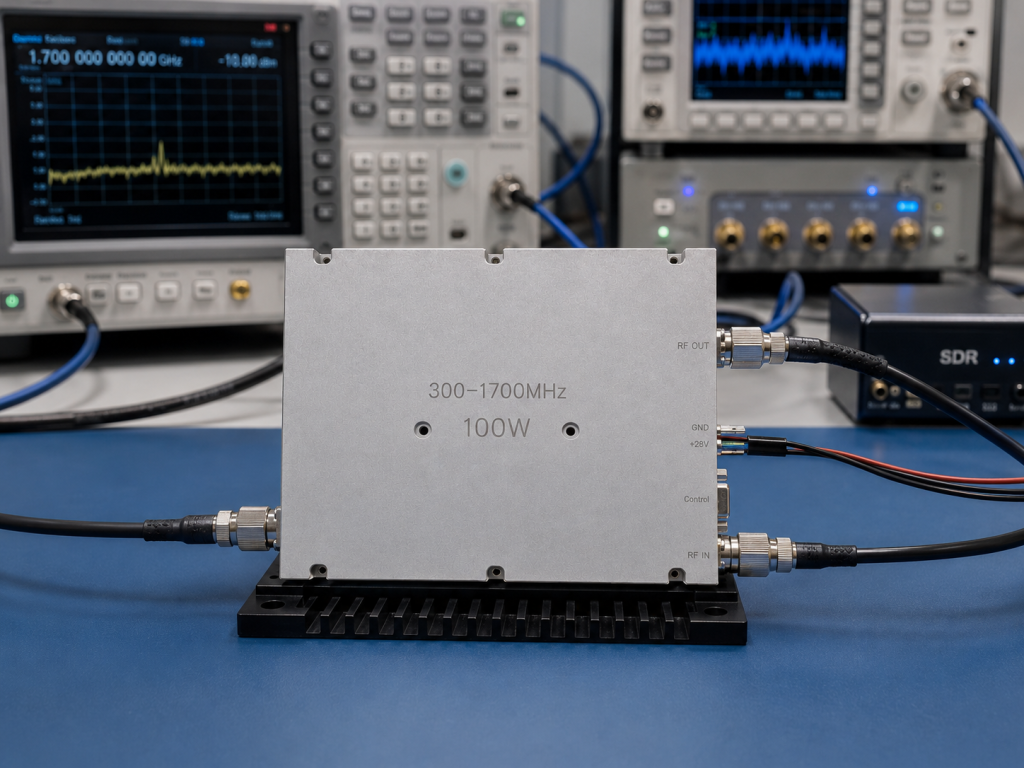
Confirm drive level, gain, and source behavior
The CRF-PA-300M1700M-100W is listed with 50 dB typical gain. That gives the system designer a starting point for drive-level calculations, but it does not replace a full RF chain review. Signal generator output, SDR source output, driver stages, filters, and attenuators must be included in the gain plan.
For SDR amplifier integration, define waveform type, occupied bandwidth, duty cycle, crest factor, sweep behavior, and source output power. For communication test platforms, define channels, modulation, output target, and load condition. For RF testing and validation, define the calibration plane and measurement points.
Cooling and mechanical fit should be reviewed early
CorelixRF lists air cooling and a 200 x 158 x 25 mm size for the 100 W model. These details matter in OEM systems where airflow, mounting surface, cable routing, and enclosure temperature can decide whether the module will operate reliably.
Air cooling should be reviewed with the actual duty cycle, ambient temperature, enclosure space, and airflow path. If the amplifier is placed inside a compact enclosure, the integrator should confirm inlet temperature, outlet restriction, fan behavior, mounting orientation, and service access. A module that is suitable on an open bench may need additional thermal planning inside a sealed or dense system.
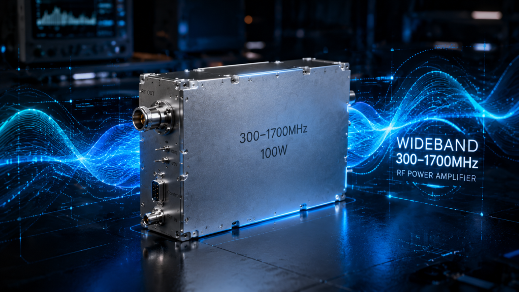
Interfaces and documentation
The standard interface reference for the 300-1700 MHz family includes SMA-F input and N-F output. These connectors should be checked against system cable types, output path power handling, panel placement, and bend radius. If a different connector or mounting arrangement is needed, request custom RF development review before locking the mechanical design.
Documentation should also be defined in the RFQ. CorelixRF states that model-specific datasheets, gain/frequency curves, mechanical drawings, and unit test reports can be available after engineering intake. Ask for the data that directly supports your receiving inspection and integration workflow.
FAQ
What is the CRF-PA-300M1700M-100W used for?
It is a 300-1700 MHz, 100 W broadband RF amplifier model for OEM integration, RF testing, communication platforms, wideband transmit chains, and C-UAS RF chain evaluation.
What gain is listed for the CRF-PA-300M1700M-100W?
CorelixRF lists 50 dB typical gain for the 100 W model in the 300-1700 MHz family.
What supply and cooling method are listed?
The public page lists 28 VDC supply and air cooling for the 300-1700 MHz standard family.
Can this model be customized?
CorelixRF states that custom frequency subsets, connector configurations, mechanical details, and OEM review can be discussed by project requirement.
What should I send for quotation?
Send frequency range, output power target, operating mode, input drive level, cooling condition, load or antenna path, connector preference, documentation needs, quantity, and project stage.
Conclusion
The CRF-PA-300M1700M-100W RF amplifier is best specified as part of a complete RF chain. Confirm frequency coverage, drive level, delivered power, cooling, connector path, documentation, and validation data before selection. For OEM projects, the 100 W class can be a practical baseline when the system needs useful broadband output without immediately moving to the highest standard power class.