
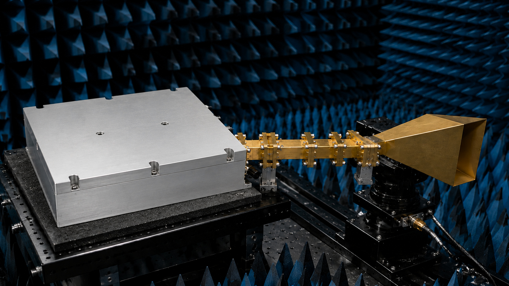
A 10.7 to 12.7 GHz 100 W RF amplifier is usually selected for a narrower and more interface-sensitive part of the microwave system than a general multi-octave amplifier. The CorelixRF CRF-PA-10700M12700M-100W local datasheet provides a new, unused model direction for X/Ku-band test and integration content: 10.7 to 12.7 GHz coverage, 100 W typical rated output power, GaN SSPA technology, 50 dB minimum gain, 20 dB gain control in 1 dB steps, SMA-F input and WR75 output.
This article should not present the unit as a universal satellite, radar or compliance solution. The safer and more useful angle is to explain how engineers and buyers can review the amplifier against an actual RF path. At 10.7-12.7 GHz, the interface plan, gain-control requirement, source drive level, thermal environment and output measurement method matter as much as the headline output-power value.
What the Local Datasheet Confirms
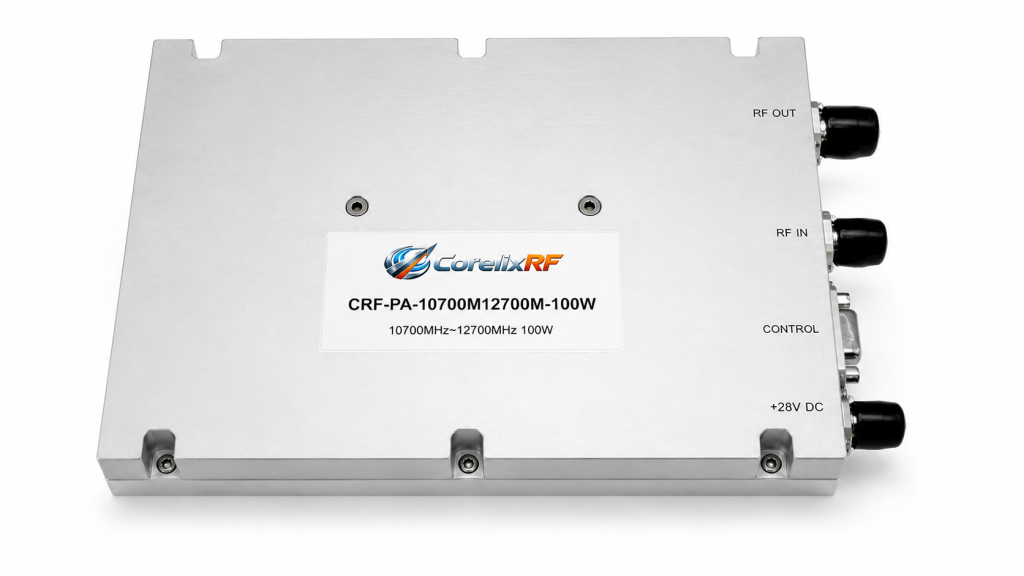
The CRF-PA-10700M12700M-100W is described as a solid-state RF power amplifier for test and measurement instrumentation, communication systems, RF interference system-level testing and aerospace control. It uses advanced GaN technology and integrates temperature and current monitoring, alarm protection and project-ready control interfaces.
Why WR75 Output Changes the Integration Plan
A WR75 output interface is not just a connector note. It defines the output hardware path and the measurement approach. If the existing test bench expects coaxial output hardware, the transition plan must be reviewed before procurement. Waveguide bends, transitions, couplers, loads and antennas can each add loss or mismatch, so the delivered power at the load should be calculated, not assumed from the amplifier rating.
This is also why a custom RF amplifier review should include drawings or a simple block diagram. If the amplifier will drive a waveguide component, chamber path or subsystem input, CorelixRF can review whether the requested interface, mechanical fit and monitoring functions align with the final setup.
Gain Control and Source-Level Planning
The local datasheet lists 50 dB minimum gain and 20 dB gain control in 1 dB steps. This is useful for test systems where the engineer needs repeatable output-level control while keeping the signal source in a clean range. It also means the source maximum output must be limited carefully. A small drive-level mistake can create a much larger output-level error when the amplifier has high gain.
For automated benches, RS485 control should be included in the test script design. The controller should track frequency, requested gain state, input level, alarm status and temperature/current state. That workflow is consistent with CorelixRF RF power amplifier technical insights content, where test evidence and integration context support better amplifier selection.
Cooling and Protection Review
The datasheet states that system-level forced-air cooling is required. That is a direct reminder that the amplifier is not selected independently from its enclosure. Airflow, heat path, operating temperature and service access need to be reviewed before final installation. If the unit is placed in a restricted rack, the thermal behavior may differ from a lab bench validation setup.
Protection features include over-temperature protection, over-drive protection, over-voltage protection, VSWR protection and alarm functions. These should be treated as part of the operating procedure. The safest commissioning path starts with verified load and interface hardware, low drive level, alarm-state check, then controlled increase to the required operating point.
Validation Data to Request
For this frequency range, request configuration-specific gain response, output-power data, interface notes and thermal guidance rather than relying only on nominal model information. If the amplifier will be used in a repeatable production or qualification bench, ask how alarm states and gain settings should be recorded through the RS485 interface.
Where This New Model Fits in Content Strategy
This topic avoids the already-used 2-6 GHz, 2-8 GHz, 6-18 GHz, 18-40 GHz and mmWave model themes. It targets a narrower long-tail keyword with clear engineering intent: X/Ku-band 100 W amplifier selection. It can naturally link readers to CorelixRF’s broader RF power amplifier portfolio without repeating older article subjects.
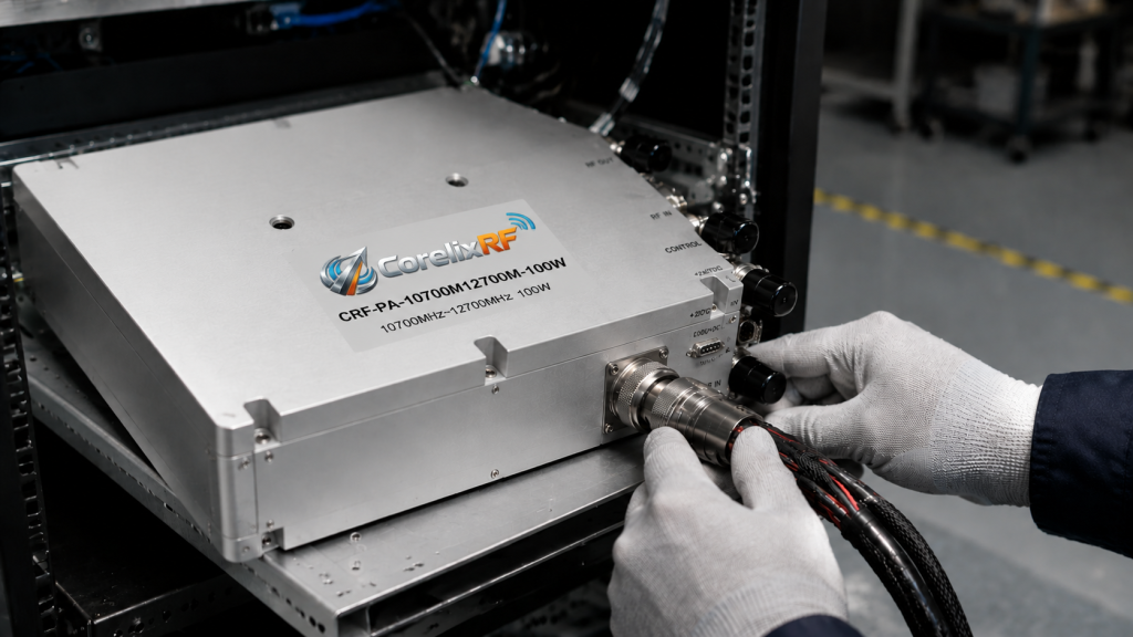
Procurement teams should send the exact frequency window, required output at the WR75 interface, source level, waveform, CW or pulsed operation, duty cycle, control requirement, DC power constraints, cooling environment and validation data needs. That gives engineering enough context to confirm whether the CRF-PA-10700M12700M-100W is a fit or whether a different configuration should be reviewed.
FAQ
What frequency range does the CRF-PA-10700M12700M-100W cover?
The local datasheet lists 10.7 to 12.7 GHz coverage.
What output interface is listed for this model?
The datasheet lists SMA-F input and WR75 output, so waveguide interface planning should be included in the RFQ.
Why is gain control important for this amplifier?
The model lists 20 dB gain control in 1 dB steps, which helps controlled test systems set repeatable output levels.
What should be sent for engineering review?
Send frequency range, required output, source level, waveform, duty cycle, interface path, cooling limits, control needs and validation requirements.