
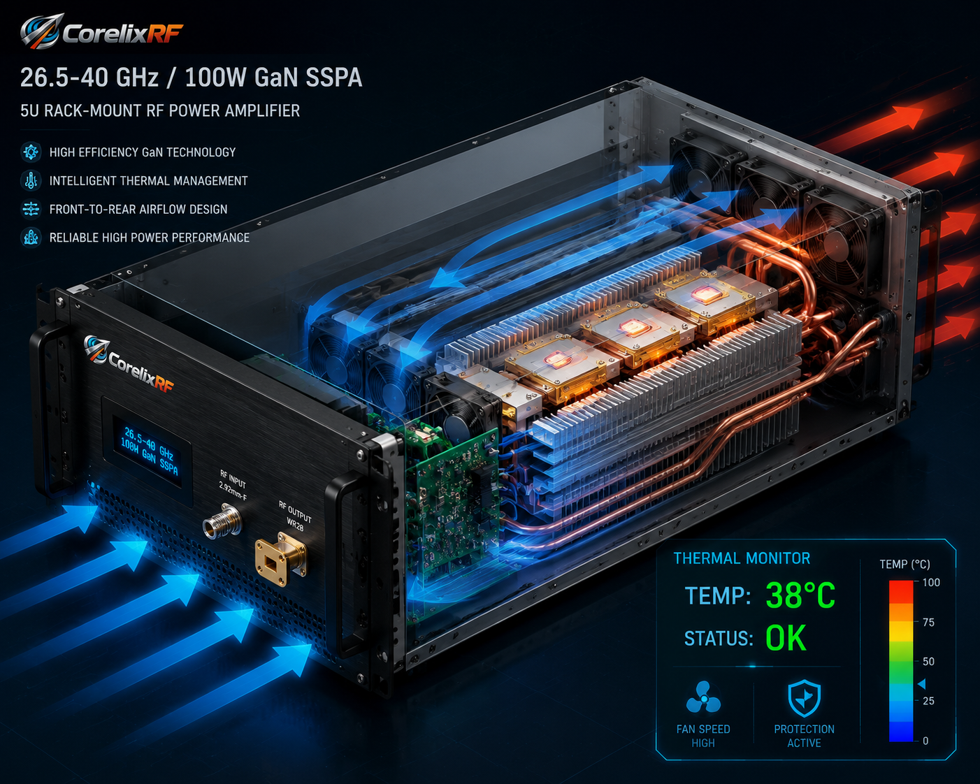
A 26.5 to 40 GHz Ka-band RF amplifier should be selected with more care than a lower-frequency bench amplifier. At Ka-band, connector choice, waveguide transitions, output power measurement, thermal margin and mechanical alignment can change the result as much as the amplifier specification itself. The CorelixRF CRF-PA-26500M40000M-100W local datasheet gives a practical starting point for this review.
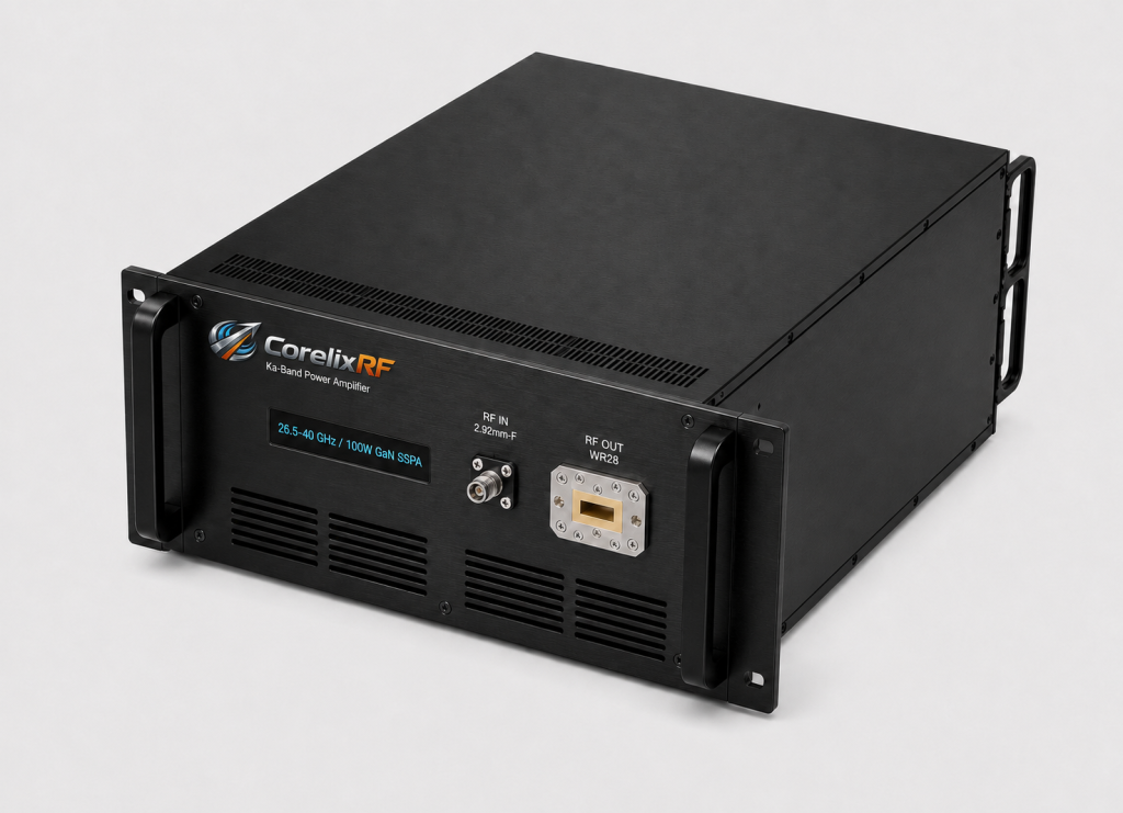
The datasheet lists 26.5 to 40 GHz coverage, 100 W rated output power, GaN SSPA technology, 53 dB minimum small-signal gain and a 19-inch 5U rack-mount form factor. The RF interface is listed as 2.92 mm-F / WR28, control is RS485 / LAN, and cooling is forced air. These details point to an amplifier that belongs in a planned microwave system, not a casual plug-in bench setup.
Why Ka-Band Selection Is Different
At 26.5-40 GHz, a high frequency RF amplifier is part of a precision RF path. Small mechanical differences in adapters, waveguide transitions and cable routing can affect loss, repeatability and power handling. Engineers should define the interface chain before finalizing the amplifier because the output path may involve waveguide hardware, couplers, loads, antennas or test ports that are not interchangeable.
CorelixRF’s public high-frequency capability page emphasizes that 2-40 GHz projects should review power, gain, interface, cooling, validation and integration conditions before datasheet matching. The local datasheet supplies model-level values for one 26.5-40 GHz platform, but the final recommendation still depends on the project.
Interface Planning: 2.92 mm and WR28
The local datasheet lists 2.92 mm-F / WR28, which signals that interface selection is part of the project discussion. Coaxial connections can be convenient for instruments, while WR28 waveguide may be appropriate for the output path depending on power level and system geometry. A custom RF amplifier request should include the preferred interface and any existing fixture drawings.
Cooling, Control and Protection
The amplifier is specified as forced-air cooled in a 5U rack format. Airflow, rack spacing and exhaust path should be confirmed before long sweeps or thermal validation. The datasheet also lists temperature and current monitoring, alarm protection, and project-ready control interfaces. In a Ka-band system, these monitoring points help separate RF path problems from amplifier operating conditions.
Use Cases That Fit This Class
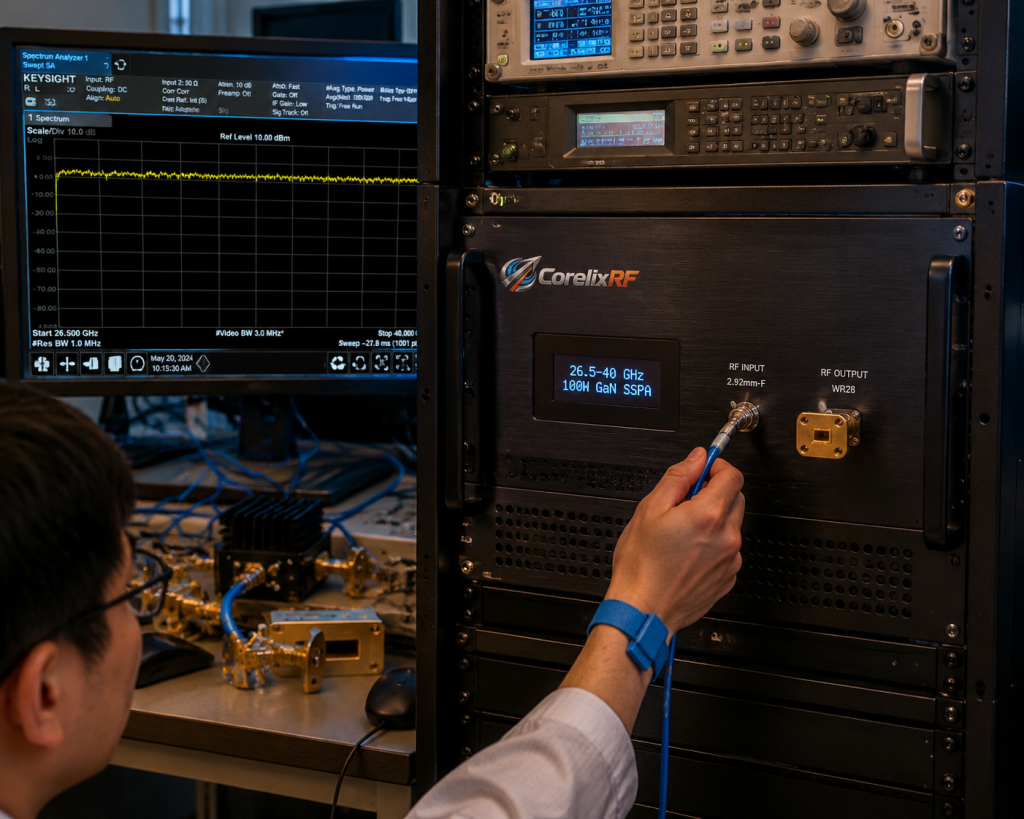
A 26.5-40 GHz 100 W amplifier may fit Ka-band RF test benches, radar front-end evaluation, communication link testing, signal-environment simulation and high-frequency subsystem integration when requirements match the datasheet. It can also support RF testing and validation workflows where measured output power, gain, spectrum, VSWR behavior and thermal records are needed before acceptance.
Purchasing teams should avoid treating this as a simple catalog item; CorelixRF’s RF power amplifier technical insights can also help teams prepare better review questions before formal RFQ. The inquiry should include frequency window, required output at the load, interface preference, operating mode, cooling constraints, rack space, measurement method and documentation needs. If the requirement is still broad, start from CorelixRF’s RF amplifier product overview and narrow the band during engineering review.
Validation Data to Request
For a Ka-band amplifier, ask for validation data that matches the operating window rather than a broad generic statement. Useful data may include output power across the requested band, small-signal gain response, harmonic or spurious information, thermal behavior during representative operation, and interface or outline details. If the project requires a waveguide output path, include the target waveguide hardware and measurement method so the review does not assume the wrong transition.
The CRF-PA-26500M40000M-100W datasheet describes a GaN RF amplifier platform with monitoring and alarm functions. In practice, those functions are most valuable when they are connected to the test procedure. A system controller should log alarm states, temperature state and RF level decisions together, especially during long sweeps or automated validation.
RFQ Details That Reduce Back-and-Forth
Send the exact frequency range, minimum delivered power, source type, input drive limit, waveform, duty cycle, RF interface preference, cooling environment, rack constraints and required documentation. If the amplifier will drive an antenna or chamber path, include antenna gain, cable loss, coupler loss and expected mismatch. For broader high-frequency projects, CorelixRF can review adjacent microwave amplifier platforms or a custom RF amplifier configuration rather than forcing the requirement into a single published model family.
How Procurement and Engineering Can Work Together
Procurement can speed the project by separating commercial questions from engineering fit questions. Commercial teams can ask about quotation, delivery path and documentation format, while engineers provide the operating envelope and acceptance criteria. For a Ka-band solid state power amplifier , the technical package should be reviewed before price-only comparison because the wrong interface or cooling assumption can add redesign work later.
It is also useful to identify whether the amplifier will be used as a lab instrument, a subsystem prototype or part of an OEM-style integration. A lab instrument may need front-panel usability and flexible control. A subsystem prototype may prioritize mechanical envelope, remote monitoring and repeatable startup behavior. OEM integration may require a deeper custom RF development review around control protocol, drawings and validation records.
FAQ
What frequency range is covered by this CorelixRF Ka-band model?
The local datasheet for CRF-PA-26500M40000M-100W lists 26.5 to 40 GHz coverage.
What RF interface is listed?
The datasheet lists 2.92 mm-F / WR28, so coaxial and waveguide interface planning should be reviewed.
Why is measured data important at Ka-band?
Loss, mismatch and interface transitions can strongly affect delivered power and repeatability at these frequencies.
Is this a custom-only product?
The local datasheet provides a reference model, but final configuration and datasheet matching should be reviewed against the actual project.