
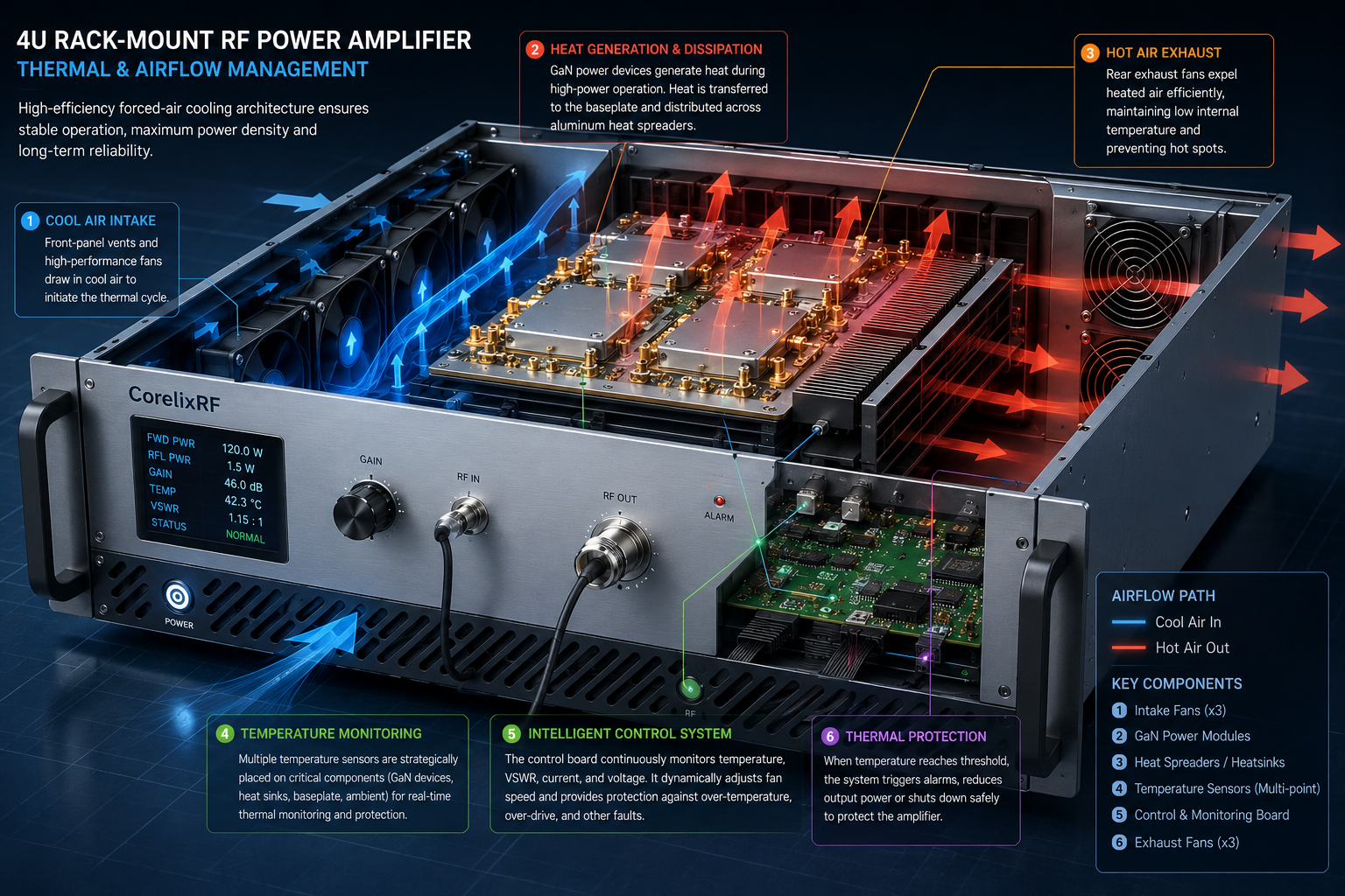
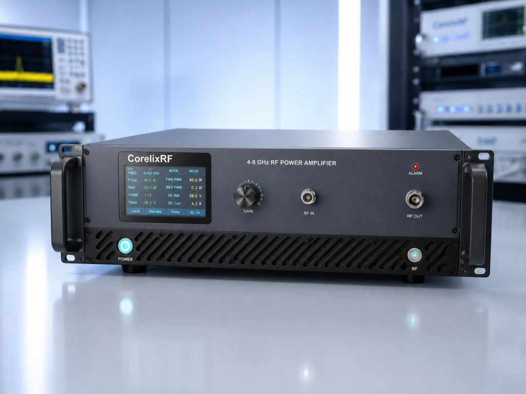
CorelixRF CRF-PA-4000M8000M-120W is a 4-8 GHz C-band RF power amplifier selected for a different article direction than the earlier repeated 2-18 GHz, 18-26.5 GHz, 18-40 GHz, and 2.7-3.1 GHz topics. The supplied specification identifies this amplifier as a GaN solid-state RF power amplifier covering 4 GHz to 8 GHz with 120 W rated output power. It is intended for test and measurement instrumentation, communication systems, RF interference or EW system-level testing, aerospace control, and RF system integration. For engineers and technical buyers, the goal is to match the amplifier to a real operating profile rather than only choosing a model by maximum output power.
Why This Frequency Range Matters
The 4 GHz to 8 GHz range is a focused C-band topic for radar-related test paths, communication subsystem validation, broadband fixture drive, and RF interference system-level testing. A well-matched amplifier can reduce fixture changes, simplify test planning, and provide enough output power without forcing an oversized rack or cooling system. The selection still needs engineering review because waveform type, duty cycle, input drive, output load, mismatch exposure, ambient temperature, and measurement location all influence final performance. CorelixRF CRF-PA-4000M8000M-120W gives buyers a documented starting point for this review, with specifications that can be checked against the customer’s RF path and acceptance criteria.
Core Specification Basis
The datasheet lists 4 GHz to 8 GHz frequency coverage, 120 W rated output power, and 51 dB minimum small-signal gain. The source data also lists gain flatness, harmonic and spurious limits, input impedance, input power limits, operating temperature, and protection functions. RF interfaces are N-F input and N-F output. The control interface is RS485 / LAN, and the power supply is AC 220 V +/-10%, 50/60 Hz. Mechanical form factor is 19-inch 4U rack-mount. Cooling is forced-air cooling. These are the values that should guide early comparison, while final procurement should still reference the exact quoted configuration and production test data.
Integration Planning
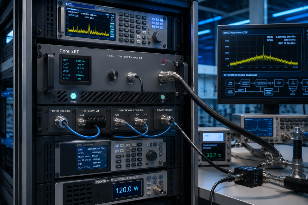
RF amplifier integration should start with the complete signal path. The source, attenuator, cable, switch, coupler, sensor, load, antenna, or chamber must all be rated for the operating band and expected power. At 4 GHz to 8 GHz, connector repeatability, cable loss, load match, and thermal behavior can create measurement differences that look like amplifier variation if the test setup is not controlled. Engineers should define whether output power is required at the amplifier connector, after cable loss, or at the device under test. That decision affects both amplifier sizing and acceptance testing.
Thermal and Mechanical Review
This 4U forced-air amplifier should be planned with rack airflow, connector clearance, and front or rear cable routing in mind. The mechanical drawing, airflow path, mounting method, power input, RF connector clearance, and service access should be reviewed before installation. If the amplifier will run repeated automated cycles, thermal recovery and ambient conditions should be included in the review. If it will be installed inside another enclosure, the cooling approach may need more margin than an open-bench setup. For liquid-cooled or high-power units, the cooling infrastructure should be treated as part of the RF system, not as an accessory added later.
Control, Monitoring, and Protection
The product family information includes temperature monitoring, current monitoring, alarm protection, over-temperature protection, over-drive protection, over-voltage protection, and VSWR or load-mismatch protection behavior where applicable. Depending on configuration, forward and reverse power monitoring, input power detection, LAN remote monitoring, GPIB, or project-specific control interfaces may also be reviewed. These functions are important for automated benches and system-level testing because the amplifier often has to coordinate with signal sources, switching equipment, sensors, interlocks, and data acquisition software.
Application Fit
CRF-PA-4000M8000M-120W is relevant for C-band RF power amplifier buyers who need a focused 120 W platform instead of another multi-octave mmWave article. The model is useful when buyers need a different product angle from commonly repeated broadband microwave topics. It can support RF test benches, EMC-related testing, communication subsystem evaluation, SDR or OFDM-type signal chains, EW or RF interference development, aerospace validation, and custom system integration. If the project requires unusual duty cycle, special control logic, environmental qualification, a different connector set, or dedicated test data, CorelixRF should review the requirement as a custom RF amplifier project.
RFQ Checklist
A clear RFQ should include exact frequency range, output power at the required measurement point, waveform type, CW or pulse mode, duty cycle, input drive level, gain-control needs, load VSWR, connector preference, cooling environment, control interface, protection expectations, and factory test-data requirements. If the amplifier will drive an antenna, chamber, or fixture, include expected losses and mismatch conditions. If it will be part of a rack or automated system, include remote-control and fault-reset expectations. That information helps confirm whether CRF-PA-4000M8000M-120W is suitable or whether another CorelixRF configuration is a better fit.
Frequently Asked Questions
Q1: What frequency range does CRF-PA-4000M8000M-120W cover?
It is specified for 4 GHz to 8 GHz operation.
Q2: What output power is listed?
The supplied product data lists 120 W rated output power.
Q3: What gain is specified?
The datasheet lists 51 dB minimum small-signal gain.
Q4: What interfaces should engineers plan around?
The RF interfaces are N-F input and N-F output, and the control interface is RS485 / LAN.
Q5: What should be sent to CorelixRF for review?
Send frequency range, output power, waveform, duty cycle, input drive, load condition, cooling plan, connector requirements, control needs, and test-data expectations.
CTA: Contact CorelixRF to review your 4-8 GHz C-band RF power amplifier requirement.