
Why a 2-6 GHz 1000W amplifier changes the whole test-system plan
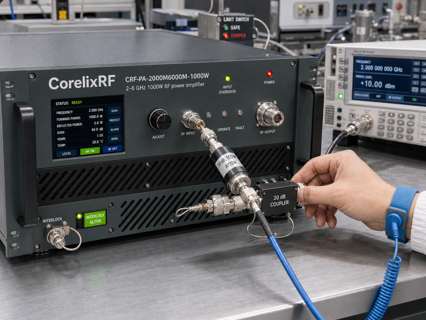
A 2-6 GHz 1000W RF power amplifier is a system-level power source for demanding broadband S-band and C-band work. The CorelixRF CRF-PA-2000M6000M-1000W is a GaN solid state power amplifier covering 2,000-6,000 MHz with 1000 W rated output power, 63 dB minimum small-signal gain, N-Female input, 7/16 output, RS485/LAN control, AC 380 V supply, and water cooling.
This class of amplifier is selected when a test system needs real power margin across a multi-octave range. It can support test and measurement instrumentation, communication system verification, RF interference or EW system-level testing, and aerospace control-related RF projects. At this level, the amplifier is not just another rack item. It shapes the facility power, coolant loop, output path, safety process, monitoring strategy, and acceptance test method.
Core specifications to review first
The CRF-PA-2000M6000M-1000W operates from 2 GHz to 6 GHz. Rated output power is 1000 W, and minimum small-signal gain is 63 dB. Gain flatness is listed from -4 dB to +4 dB. Input impedance is 50 ohms, input VSWR is listed at 2:1, and maximum input power is 0 dBm.
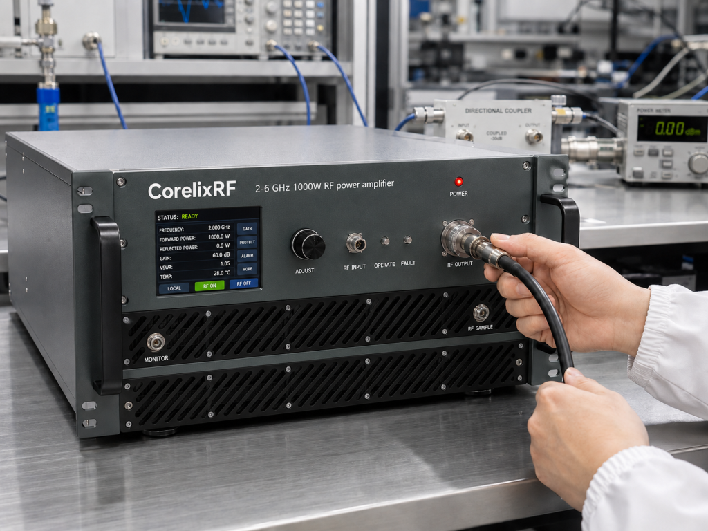
The N-Female input and 7/16 output connector pairing is important. The input side remains compatible with common RF rack cabling, while the output side is better suited to high-power coaxial paths. Still, every downstream item must be reviewed: cable assemblies, directional couplers, loads, attenuators, switch paths, adapters, feedthroughs, and antennas.
Control is through RS485/LAN. The source data lists real-time temperature monitoring, real-time current monitoring, optional forward/reverse power monitoring, and optional LAN remote monitoring. These functions are exactly the kind of visibility high-power RF teams should request.
Water cooling and facility planning
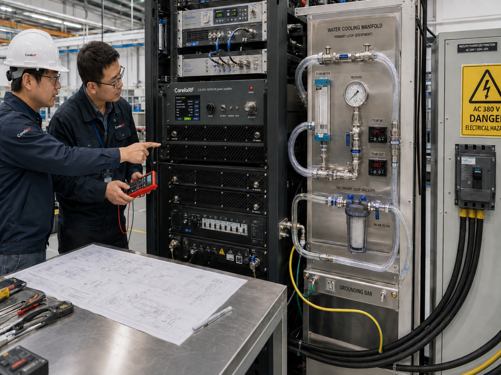
The extracted specification lists water cooling and AC 380 V +/-10% supply. Those two details move the model into coordinated project territory. RF, mechanical, electrical, and facility teams should review the installation together. Coolant flow, fittings, leak management, service access, grounding, cabinet clearances, and safe operating procedures should be defined before final procurement.
Water cooling can help manage a high-power amplifier more effectively than air cooling, but it adds design responsibility. The coolant path must be stable, maintainable, and compatible with the installation environment. If the system will run long sweeps or repeated tests, coolant performance should be considered part of the RF system reliability plan.
Power-level and drive-chain discipline
With 63 dB minimum gain and a 0 dBm maximum input-power limit, the drive chain deserves careful protection. A signal generator, SDR source, upconverter, or driver amplifier should not be allowed to overdrive the input during startup, frequency changes, or software errors. Use fixed attenuation, drive limits, enable sequencing, and interlocks where appropriate.
The output level should also be defined at the correct reference plane. A kilowatt at the amplifier output is not the same as delivered power at an antenna, chamber feed, fixture, or device under test. Cable loss, coupler loss, switch loss, and mismatch can change the real delivered level. Engineers should build a calibration table around the complete RF path.
Applications and best fit
This model fits high-power broadband RF testing where one amplifier must cover 2-6 GHz without swapping bands. It can help communication teams test RF front ends, support system-level EW or interference evaluation, and provide power margin for conducted or radiated setups. The right positioning is not a generic claim of universal compliance. The accurate positioning is a configurable GaN SSPA platform that should be reviewed against each project’s waveform, duty cycle, load, cooling, and control requirements.
RFQ checklist
A useful RFQ should include target frequencies, required output power at the load, waveform type, CW or pulse operation, duty cycle, modulation, input drive range, expected load VSWR, control interface, facility power, coolant requirements, mechanical constraints, monitoring needs, and documentation expectations. Ask for mechanical drawings, test data, control protocol details, and cooling recommendations.
Verification planning before delivery
For a 1000 W broadband amplifier, acceptance planning should start before the purchase order is complete. The buyer should decide which frequency points need output-power confirmation, what load will be used, how long each test condition must run, and whether the test should verify only saturated power or also gain, harmonics, spurious response, and monitoring behavior.
It is also useful to separate amplifier verification from system verification. The amplifier may pass its own test data, but the integrated rack can still lose power through switches, cables, filters, or couplers. A clean project plan defines both reference planes: the amplifier output and the final point where power must be delivered.
Buyer and integrator responsibilities
Procurement teams often focus on the model number and power level, but integrators need more detail. Ask who supplies the coolant loop, who validates the output cable path, who maps RS485/LAN commands into the system controller, and who defines fault recovery. These questions make ownership clear.
The 2-6 GHz 1000 W class can be very effective when treated as a complete RF power subsystem. It becomes risky only when the amplifier is purchased first and the facility, cooling, load, and software details are solved later.
FAQ
What frequency range does the CRF-PA-2000M6000M-1000W cover?
It covers 2,000-6,000 MHz, or 2-6 GHz.
What output power is listed?
The rated output power is 1000 W.
What gain is specified?
The minimum small-signal gain is 63 dB, with gain flatness from -4 dB to +4 dB.
What cooling method is listed?
The source data lists water cooling.
Why should buyers request project review?
The high output power, AC 380 V supply, water cooling, and high-power RF output path must be matched to the exact system environment.
CTA
Discuss Your 2-6 GHz 1000W RF Amplifier Project with CorelixRF.