
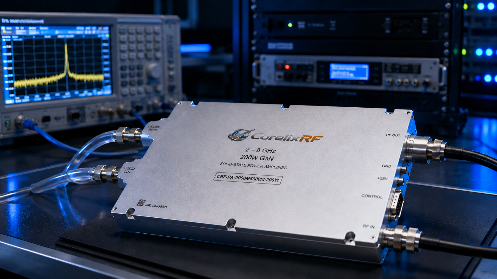
A 2-8 GHz 200W amplifier for wideband test coverage
A 2-8 GHz 200W RF power amplifier is useful when a microwave test system needs more headroom than a compact module but does not require a kilowatt-class source. The CorelixRF CRF-PA-2000M8000M-200W-Liquid is represented in the source file as a 2-8 GHz, 200 W GaN SSPA with 53 dB minimum small-signal gain, N-Female input and output connectors, RS485/LAN control, AC 220 V supply, and water cooling.
The 2-8 GHz range can support S-band and C-band test work, communication system verification, RF front-end evaluation, RF interference or EW system-level testing, and aerospace control-related RF projects. The water-cooled configuration makes this model especially relevant where duty cycle, thermal stability, or enclosure constraints make ordinary forced-air planning less attractive.
Key specifications
The amplifier covers 2,000-8,000 MHz with 200 W rated output power. Minimum small-signal gain is 53 dB, gain flatness is listed from -4 dB to +4 dB, and gain control range is listed up to 20 dB. Input impedance is 50 ohms, input VSWR is listed at 2:1, and maximum input power is 0 dBm.
The RF connectors are N-Female at input and output. That makes cabling familiar for rack integration, but power handling still needs review. Engineers should confirm connector condition, cable rating, switch path losses, coupler ratings, adapter quality, and load capacity across the complete 2-8 GHz span.
The control interface is RS485/LAN. The source data lists real-time temperature monitoring, real-time current monitoring, optional forward/reverse power monitoring, and optional input power detection.
Why water cooling matters
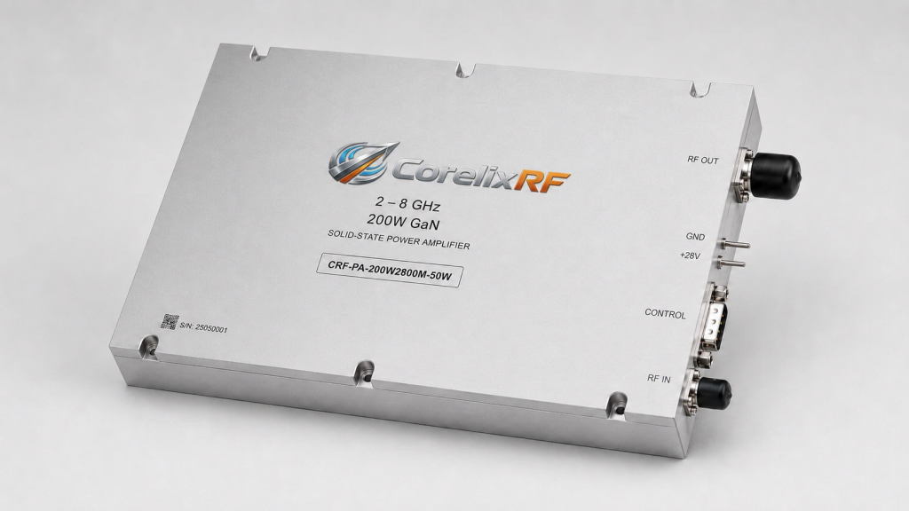
Water cooling is not only about removing heat. It can also help make the thermal environment more predictable when the amplifier is embedded in a dense rack, cabinet, or test platform. That matters for repeated testing, long-duration operation, and systems where airflow paths are difficult to control.
The project team should define coolant flow, fitting style, maintenance access, leak detection expectations, and allowable coolant temperature. If the amplifier will be installed near sensitive electronics, mechanical planning should include routing and service procedures. A good cooling plan makes the RF amplifier easier to own, not just easier to run once.
Integration and output-level planning
The 20 dB gain-control range gives engineers flexibility, but it should be used within a defined leveling strategy. Some test benches control output by changing source power. Others use amplifier gain commands or a closed loop with couplers and meters. The correct method depends on accuracy needs, sweep speed, waveform, and how much automation the rack uses.
At 200 W, mismatch and path loss still matter. If the amplifier drives antennas, fixtures, or variable test loads, optional forward/reverse power monitoring may be worth including. If upstream drive sources change frequently, optional input-power detection can help protect the amplifier from accidental overdrive.
Good applications
This model fits broadband microwave test benches, communication system validation, RF front-end stress testing, and system-level evaluation where 2-8 GHz coverage is useful. It can also support teams that want a stable rack-integrated amplifier for repeated procedures rather than a temporary benchtop setup.
The best use case is a project with clearly defined power, waveform, duty, load, and control requirements. The amplifier provides the power stage, but the system design determines whether that power is delivered safely and repeatably.
RFQ checklist
Include frequency range, output power target, waveform, duty cycle, modulation, input drive level, gain-control expectations, cooling requirements, control interface, RF connector plan, load VSWR, monitoring options, and mechanical limits. Ask for mechanical drawings, coolant recommendations, test data, and control protocol information.
How to decide whether this power class is enough
A 200 W 2-8 GHz amplifier is often selected when the test team needs useful broadband power but wants to avoid the cost and complexity of a much larger amplifier. To decide whether it is enough, calculate the required power at the actual load, then subtract cable loss, switch loss, coupler loss, fixture loss, and any safety margin. The result is more useful than comparing amplifier ratings alone.
Engineers should also review how often the amplifier must operate near its rated output. A short engineering check, a swept validation process, and a repeated production test have different thermal expectations. The water-cooled configuration can help, but the duty cycle and coolant plan still need to match the real use case.
Documentation that helps future users
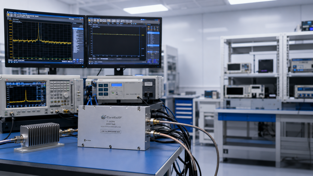
Shared labs benefit from clear documentation. Keep the amplifier model, frequency range, gain-control notes, coolant requirements, control interface, and approved RF paths in the local test procedure. Include startup and shutdown steps, especially if multiple operators use the rack. This turns the amplifier from a powerful component into a repeatable test asset.
For procurement, request configuration-specific drawings and test data. For engineering, request control protocol details early enough that software can be written before final installation.
That preparation also helps purchasing compare options fairly, because the decision becomes based on delivered power, cooling fit, controls, and documentation rather than headline wattage alone.
FAQ
What frequency range does this model cover?
It covers 2,000-8,000 MHz, or 2-8 GHz.
What output power is listed?
The rated output power is 200 W.
What gain is specified?
The minimum small-signal gain is 53 dB, with gain flatness from -4 dB to +4 dB.
What control interface is listed?
The source data lists RS485/LAN control.
What cooling method is used?
The source data lists water cooling.
CTA
Request a 2-8 GHz Water-Cooled RF Amplifier Review from CorelixRF.