
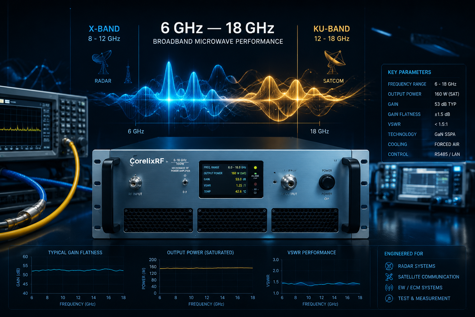
A stronger 6-18 GHz rack amplifier for microwave test systems
A 6-18 GHz 160W microwave RF power amplifier is useful when X-band and Ku-band test setups need more margin than a 100 W class amplifier can provide. The CorelixRF CRF-PA-6000M18000M-160W is a GaN solid state power amplifier covering 6,000-18,000 MHz with 160 W rated output power, 50 dB minimum small-signal gain, N-Female input and output connectors, RS485/LAN control, AC 220 V supply, air cooling, and a 4U rack-mount form factor.
This model belongs in system-level planning for test and measurement instrumentation, communication system verification, RF interference or EW testing, and aerospace control-related RF platforms. The value is not only the output-power rating. It is the combination of broadband microwave coverage, rack integration, remote control, and protection functions.
Key specifications
The CRF-PA-6000M18000M-160W covers 6 GHz to 18 GHz. Rated output power is 160 W, and minimum small-signal gain is 50 dB. Gain flatness is listed from -5 dB to +5 dB, and the gain control range is listed up to 20 dB. Maximum input power is 0 dBm, so the upstream drive chain must be controlled carefully.
The input and output connectors are N-Female. Harmonics are listed from -15 dBc typical to -8 dBc maximum, noise floor is listed at -30 dBm/MHz maximum, and spurious performance is listed at -60 dBc maximum. These values should be checked against the intended test objective because a receiver stress test, communications verification setup, and EW evaluation bench may care about different RF details.
Why 160W can be the practical choice
In 6-18 GHz systems, output power disappears quickly through cables, switches, couplers, adapters, and fixtures. A 160 W amplifier provides useful headroom while staying in a 4U air-cooled rack format. It can support conducted test paths, antenna-feed work, subsystem evaluation, and broadband microwave experiments where the test team wants one amplifier to cover multiple frequency plans.
The 20 dB gain-control capability helps when output level must change across bands or test steps. Engineers should still decide how power leveling will be handled: through amplifier gain control, upstream source correction, external attenuators, or software feedback from a power meter or detector.
Protection and monitoring
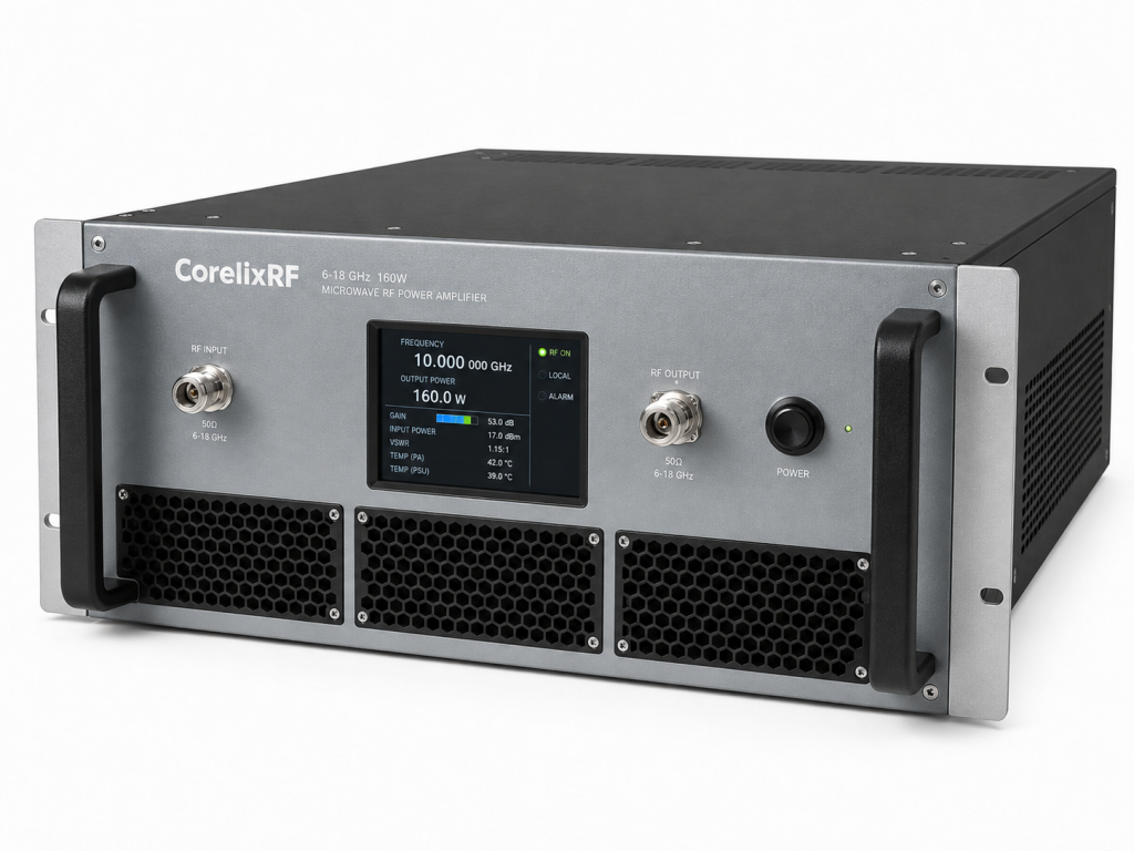
The source data lists real-time temperature monitoring, current monitoring, optional forward/reverse power monitoring, and optional LAN remote monitoring. Built-in protection includes alarm and fault functions, over-temperature protection, over-drive protection, over-voltage protection, VSWR protection, and alarm functions.
VSWR protection is particularly relevant in microwave systems. The amplifier may drive antennas, long cable paths, waveguide transitions, switches, or devices under test with changing impedance. Reflected-power events can be hard to spot without monitoring, so forward/reverse power options deserve attention when the system will be automated or operated by multiple users.
Integration planning
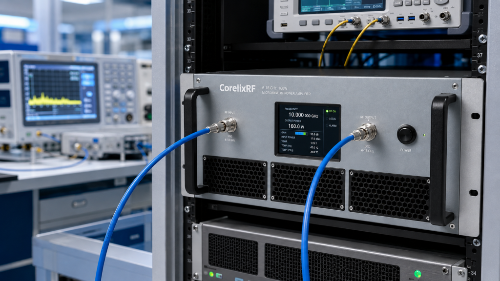
The 4U rack-mount format makes this amplifier straightforward to place in a microwave test rack, but the details still matter. Allow clear airflow, confirm AC power availability, plan rear-panel access, and define cable routing for both RF and control lines. Avoid sharp cable bends, poorly rated adapters, and output paths that have not been reviewed for power handling.
The maximum input power of 0 dBm should be treated seriously. If the source chain includes a signal generator, upconverter, driver amplifier, or SDR, add drive limits and startup procedures so the amplifier is not overdriven during configuration changes.
RFQ checklist
A complete RFQ should include frequency points, output power target, waveform, duty cycle, modulation, drive level, gain-control expectations, load VSWR, connector preferences, control interface, monitoring options, rack limits, airflow constraints, and required documentation. Ask for mechanical drawings, test data, and control protocol information before final system integration.
Choosing 160W instead of a lower or higher power class
The 160 W level is useful when the system needs extra link margin but does not justify a much larger amplifier. Compared with lower-power modules, it gives more room for cable loss, switch loss, coupler loss, and antenna-path uncertainty. Compared with very high-power rack systems, it can keep the facility and cooling plan more manageable.
That balance is especially helpful during engineering development. Early test setups often change frequency points, fixtures, and signal formats. A 6-18 GHz 160 W amplifier can stay in the rack while the rest of the setup evolves. Later, when the system moves toward production or formal validation, the same amplifier can remain part of a documented test path if its output leveling, monitoring, and protection behavior have been captured properly.
The main mistake is to specify only frequency and power. Engineers should also review spectral requirements, acceptable gain variation, expected mismatch, software control, and what happens after a fault. A clear recovery process is part of the usable amplifier system.
For procurement teams, this also creates a cleaner comparison. Instead of asking only whether two amplifiers both say 6-18 GHz, compare output power margin, rack height, cooling method, control interface, monitoring options, and how much project-specific documentation the supplier can provide.
FAQ
What frequency range does the CRF-PA-6000M18000M-160W cover?
It covers 6,000-18,000 MHz, or 6-18 GHz.
What output power is listed?
The rated output power is 160 W.
What gain is specified?
The minimum small-signal gain is 50 dB, with gain flatness from -5 dB to +5 dB.
What protection features are listed?
The source data lists over-temperature, over-drive, over-voltage, VSWR protection, alarm functions, and fault protection.
What form factor is used?
The model is listed as a 4U rack-mount amplifier with air cooling.
CTA
Get a 6-18 GHz Microwave Amplifier Recommendation from CorelixRF.