
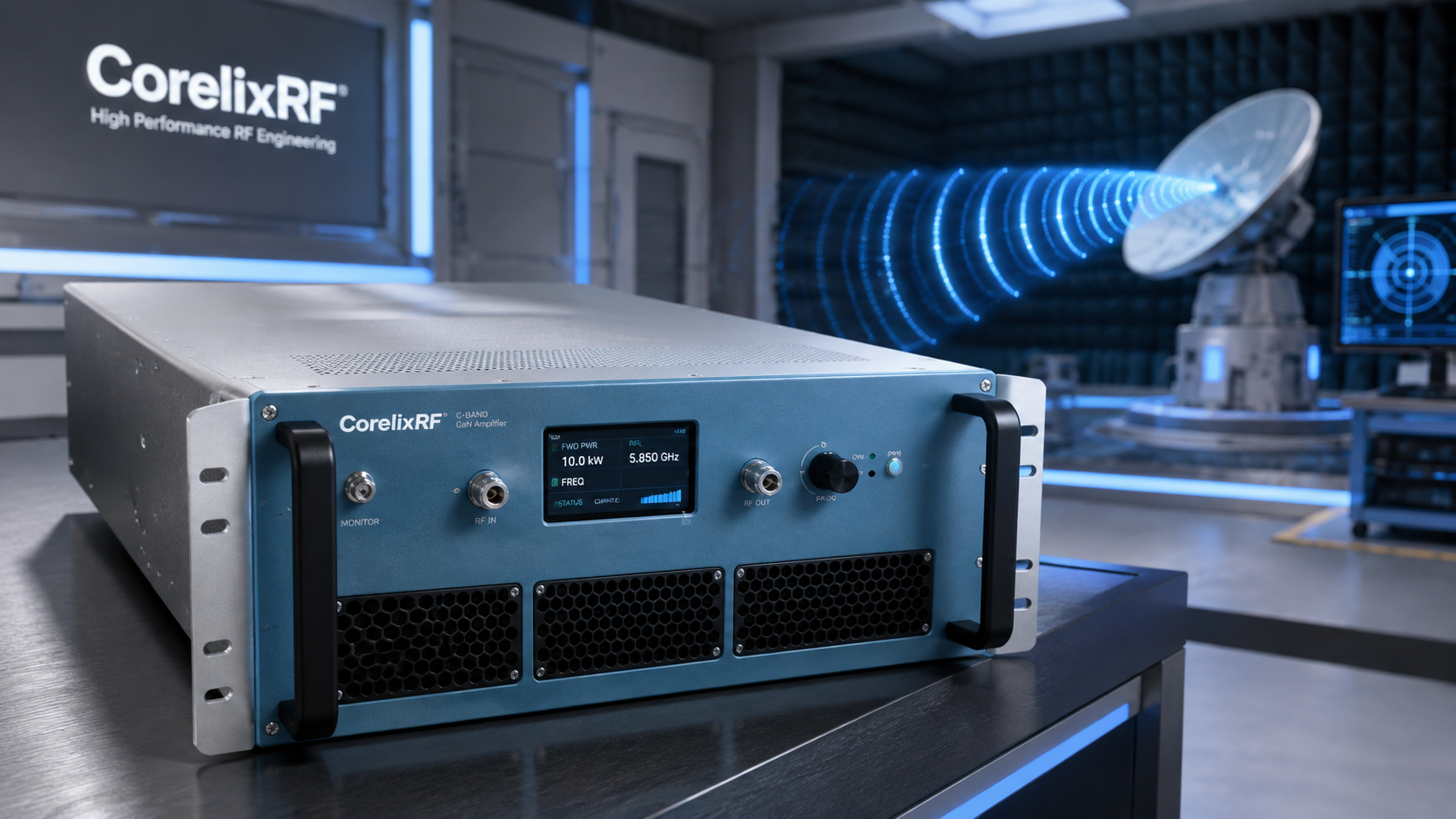
A C-band amplifier for serious but manageable power levels
A 4-8 GHz 200W RF power amplifier is a practical C-band choice when a test rack needs meaningful microwave output without moving to a larger 400 W or kilowatt-class configuration. The CorelixRF CRF-PA-4000M8000M-200W is a GaN solid state power amplifier covering 4,000-8,000 MHz with 200 W rated output power, 55 dB minimum small-signal gain, N-Female input and output connectors, RS485/LAN control, AC 220 V supply, forced-air cooling, and a 4U rack-mount format.
This model suits test and measurement instrumentation, communication systems, RF interference or EW system-level testing, and aerospace control-related RF setups. It gives engineers a wide C-band power stage that can be integrated into automated racks with monitoring, control, and protection planning.
Specifications that define the integration boundary
The CRF-PA-4000M8000M-200W operates from 4 GHz to 8 GHz. Rated output power is 200 W, and minimum small-signal gain is 55 dB. Gain flatness is listed from -4 dB to +4 dB. The input impedance is 50 ohms, input VSWR is listed at 2:1 maximum, and maximum input power is 0 dBm.
The amplifier uses N-Female connectors at both input and output. This keeps the RF path familiar for many C-band racks, but output-power handling must still be confirmed across cables, couplers, switch paths, adapters, and loads. Harmonics are listed at -15 dBc maximum, and spurious performance is listed at -60 dBc maximum.
Control is through RS485/LAN, and the unit uses AC 220 V +/-10%, 50/60 Hz. The 4U rack-mount format with forced-air cooling is convenient for systems where service access and repeatable wiring matter.
Application fit
The 4-8 GHz band is common in radar-adjacent testing, communication system evaluation, C-band RF front-end work, and microwave subsystem validation. A 200 W amplifier can support receiver stress testing, path-loss compensation, controlled radiated testing, and conducted system-level work.
The amplifier can also be useful when a team wants to simplify a multi-frequency test plan. Instead of swapping several narrower-band amplifiers, the CRF-PA-4000M8000M-200W can provide one broadband C-band power block around which the test path, calibration approach, and control logic are built.
Protection and diagnostic value
The source data lists real-time temperature monitoring, real-time current monitoring, optional forward/reverse power monitoring, and optional LAN remote monitoring. Built-in protection includes alarm and fault functions, temperature and current alarms, over-drive protection, and optional forward/reverse power monitoring.
Over-drive protection is important because a 55 dB gain amplifier can reach high output power with modest input drive. Test automation should include input limits and known startup states. If multiple operators use the same rack, clear procedures and software limits help avoid accidental overdrive.
Forward/reverse power monitoring should be considered when the load path changes, when antennas are used, or when mismatch events are possible. A C-band rack can include many components, and the amplifier is only as stable as the system around it.
Thermal and rack planning
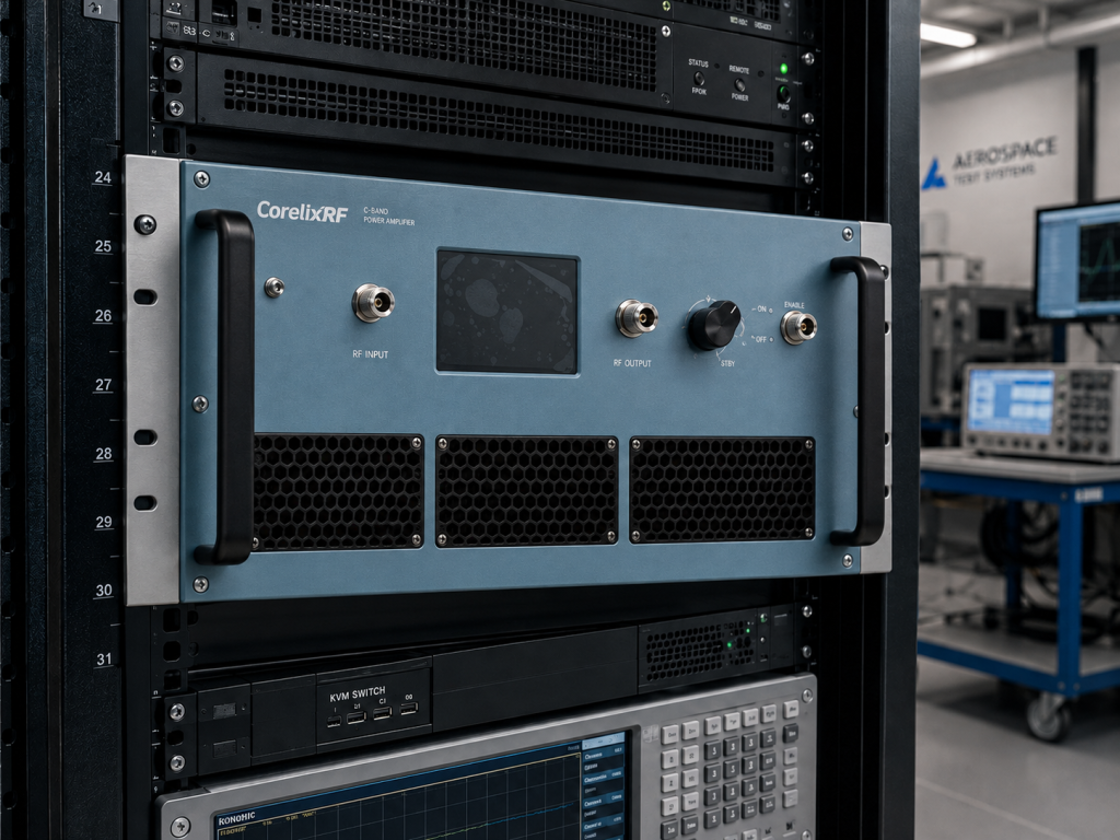
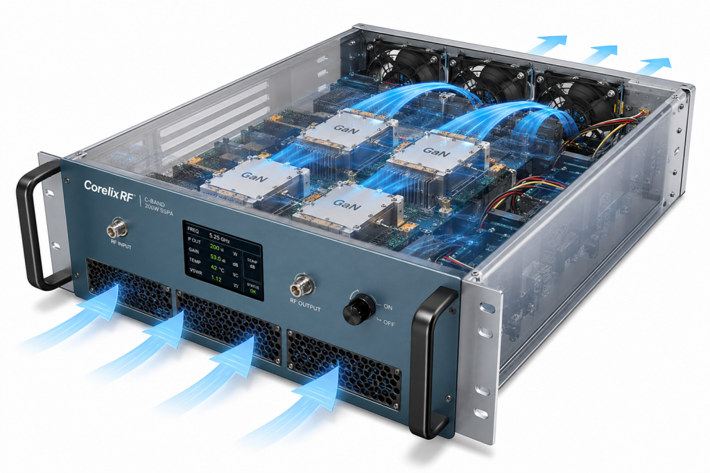
Forced-air cooling means the rack must support clear intake and exhaust flow. Engineers should avoid blocking airflow with cable bundles or placing the amplifier directly against other hot equipment. Ambient temperature, duty cycle, waveform, and output-power duration should be reviewed together.
The 4U form factor gives useful mechanical space for power handling and cooling, but it also needs proper rack depth, rear connector access, and service clearance. Include these details in the mechanical review before procurement.
RFQ checklist
Provide frequency range, required output power, waveform, duty cycle, modulation, drive source, gain-control needs, control interface, load VSWR, connector plan, rack constraints, airflow details, and monitoring requirements. Ask for mechanical drawings, control protocol details, and test data for the final configuration.
Practical calibration and output-level planning
For a 4-8 GHz 200 W amplifier, calibration should be planned around the complete RF path, not only the amplifier output. Cable loss, coupler directivity, switch insertion loss, adapter quality, and fixture mismatch can all change the delivered power. A simple frequency table can save a lot of confusion during test execution.
If the amplifier is used in swept-frequency work, decide whether output power must be constant at the amplifier output, at the device under test, or at an antenna reference plane. Those are different control problems. A directional coupler near the amplifier is useful for amplifier protection, while a calibrated measurement closer to the load may be better for test accuracy.
It is also worth defining acceptable operating margins. Running a 200 W amplifier continuously at the edge of the required output level leaves little room for temperature, path loss, or production variation. If the project needs repeatable output over long test runs, include that requirement in the review rather than discovering it during acceptance testing.
For purchasing teams, the practical question is whether the amplifier fits the whole test workflow. Ask how it will be installed, who will operate it, what status signals must be logged, and which accessories must be rated with the same care as the amplifier itself.
FAQ
What frequency range does the CRF-PA-4000M8000M-200W cover?
It covers 4,000-8,000 MHz, or 4-8 GHz.
What is the rated output power?
The rated output power is 200 W.
What gain is specified?
The minimum small-signal gain is 55 dB.
What cooling method is listed?
The source data lists forced-air cooling.
What control interface does it use?
The amplifier supports RS485/LAN control.
CTA
Discuss Your 4-8 GHz C-Band RF Amplifier Project with CorelixRF.