
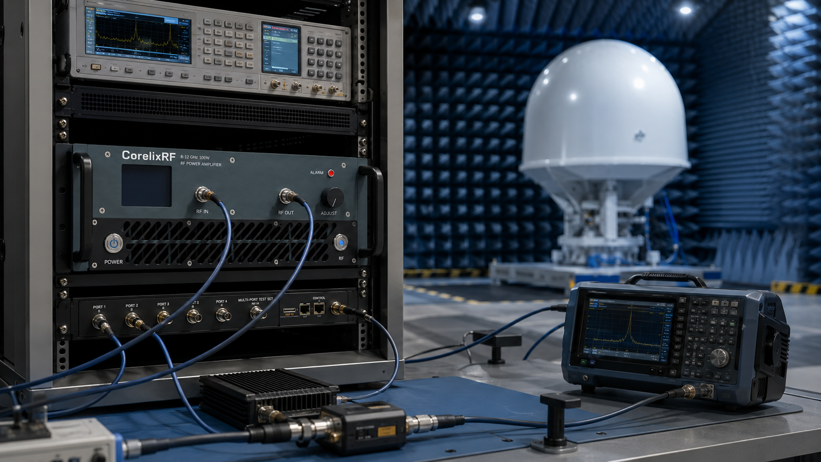
Why an 8-12 GHz 100W amplifier is useful in X-band testing
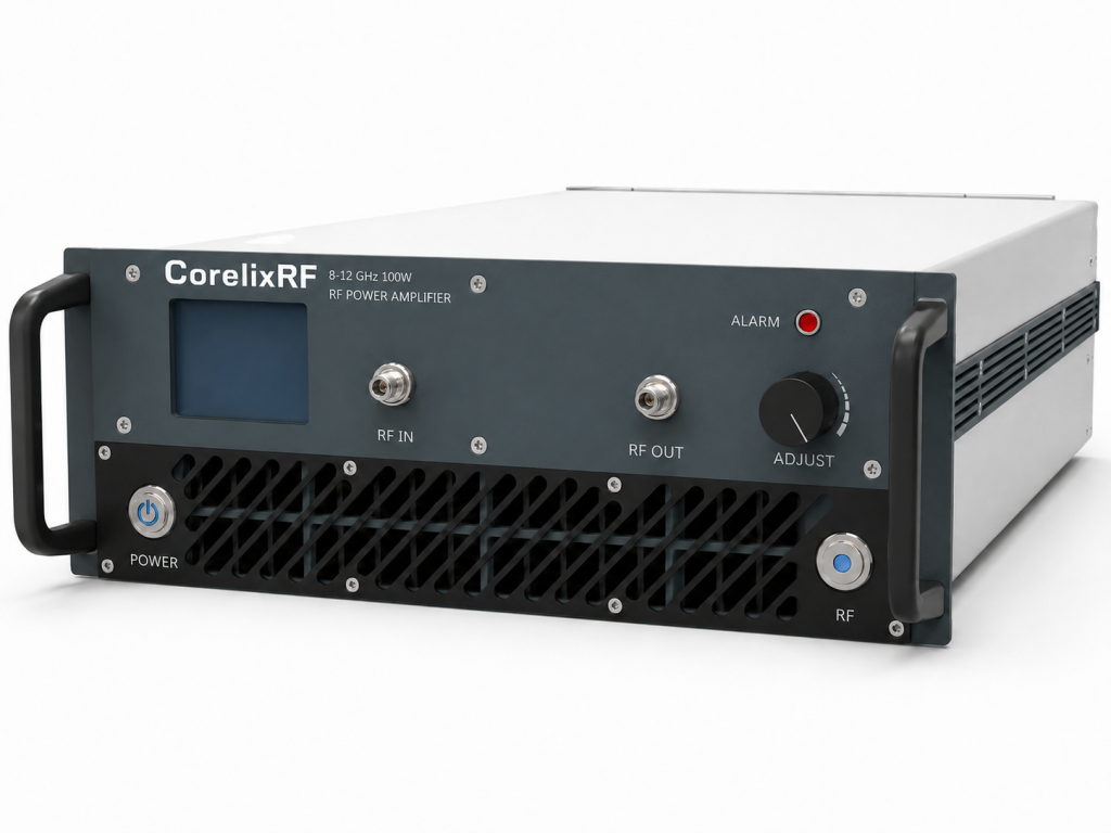
An 8-12 GHz 100W RF power amplifier gives X-band test teams a focused microwave power stage without requiring the broader 6-18 GHz span for every project. The CorelixRF CRF-PA-8000M12000M-100W is a GaN solid state power amplifier specified for 8,000-12,000 MHz operation, 100 W rated output power, 52 dB minimum small-signal gain, N-Female input and output connectors, RS485/LAN control, AC 220 V supply, air cooling, and a 19-inch 3U rack-mount form factor.
This model is relevant for test and measurement instrumentation, communication system evaluation, RF interference or EW system-level testing, and aerospace control-related RF work. Its narrower 8-12 GHz focus can be attractive when the system mainly operates in X-band and does not need a wider multi-octave amplifier.
Key specifications
The CRF-PA-8000M12000M-100W covers 8 GHz to 12 GHz. Rated output power is 100 W, and minimum small-signal gain is 52 dB. Gain flatness is listed from -3.5 dB to +3.5 dB. The gain control range is listed up to 20 dB, and maximum input power is 0 dBm.
Input VSWR is listed at 2:1 maximum. Harmonics are listed at -30 dBc maximum, noise floor at -40 dBm/MHz maximum, and spurious performance at -60 dBc maximum. RF input and output are both N-Female, which helps simplify rack cabling when the downstream path is also coaxial and rated for the intended power.
The amplifier uses RS485/LAN control and AC 220 V +/-10%, 50/60 Hz supply. The 19-inch 3U rack-mount format makes it practical for integration into standard test racks.
Application fit
For X-band communication and radar-adjacent testing, a focused 8-12 GHz amplifier can reduce unnecessary system breadth. Engineers can build the test chain around the band they actually need, with enough output power for receiver stress testing, subsystem evaluation, antenna-path drive, and controlled RF exposure setups.
The 100 W level is useful where a small module lacks margin but higher-power cabinets are not justified. It can support repeatable lab and system-level testing while keeping rack size, cooling, and facility power manageable.
Monitoring and protection
The source data lists real-time temperature monitoring, real-time current monitoring, optional forward/reverse power monitoring, optional input power detection, and alarm and fault protection functions. Temperature and current alarms are listed, along with optional over-input power protection and optional forward/reverse power monitoring.
These features are valuable in X-band racks because small changes in cables, adapters, fixtures, and antennas can affect power delivery. Input-power detection can help protect the amplifier when upstream drive conditions change. Forward/reverse power monitoring can help diagnose load mismatch or path errors.
Integration planning
The gain and maximum input-power limit should shape the drive chain. With 52 dB minimum gain and 0 dBm maximum input power, the upstream signal source must be controlled. Automated software should include level limits and startup conditions that avoid overdrive.
Air cooling requires a clear airflow path. The 3U form factor is compact, but the system still needs rack spacing, cable management, and service access. If the amplifier will run long tests or high duty cycles, ambient temperature and airflow should be reviewed.
RFQ checklist
A clear RFQ should include frequency points, output power target, waveform type, duty cycle, modulation, input drive level, gain-control requirements, RF path losses, load VSWR, control interface, monitoring needs, rack constraints, airflow conditions, and documentation needs. Ask for the mechanical drawing, control protocol, and test data for the selected configuration.
Why a focused X-band amplifier can be better than a wider unit
A wider amplifier is not always the better engineering choice. If the project is centered on 8-12 GHz, a focused X-band rack amplifier can simplify power budgeting, calibration, and procurement review. The team can concentrate on the band that matters instead of carrying extra frequency coverage that may never be used.
This can also help with test repeatability. A narrower planned operating range makes it easier to document output correction tables, cable loss, fixture behavior, and acceptance checks. The CRF-PA-8000M12000M-100W still needs careful drive control and load review, but its band focus can make the surrounding system easier to explain and maintain.
For shared labs, label the intended operating range clearly and keep the amplifier paired with suitable cables, adapters, and loads. X-band equipment is unforgiving when someone grabs the wrong adapter or assumes a cable is power-rated just because it physically fits. Good lab discipline turns the amplifier from a risky high-power source into a repeatable engineering tool.
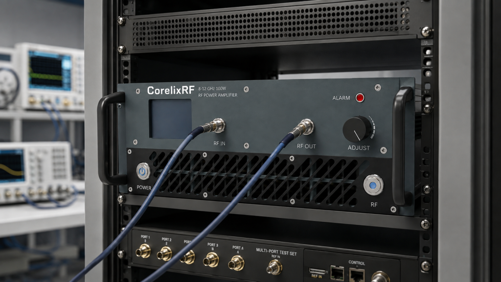
This is also a good reason to request configuration-specific documentation. Mechanical drawings, control commands, output test data, and recommended operating limits help the amplifier move from an engineering sample mindset into a stable test asset that other teams can use consistently.
That shared clarity reduces setup errors when the rack is reused across different X-band programs.
FAQ
What frequency range does the CRF-PA-8000M12000M-100W cover?
It covers 8,000-12,000 MHz, or 8-12 GHz.
What output power is listed?
The rated output power is 100 W.
What gain flatness is specified?
Gain flatness is listed from -3.5 dB to +3.5 dB.
What form factor is used?
The model is listed as a 19-inch 3U rack-mount amplifier.
What monitoring options should be considered?
Forward/reverse power monitoring, input-power detection, and LAN remote control should be reviewed for automated or shared test systems.
CTA
Contact CorelixRF to Review Your 8-12 GHz X-Band Amplifier Requirement.