
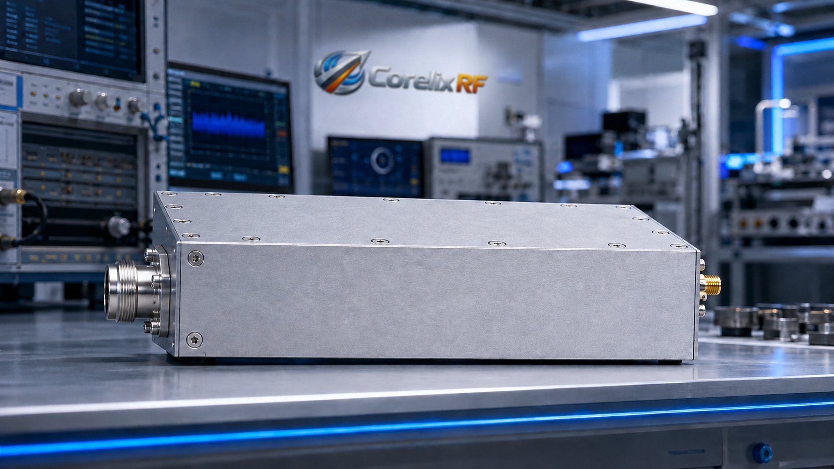
CorelixRF CRF-PA-500M2000M-25W is a 500 MHz to 2,000 MHz GaN solid-state RF power amplifier rated at 25 W output power. It is designed for test teams that need controlled broadband RF power in a rack format, but do not need a high-power amplifier that drives major changes to cooling, facility power, or RF safety planning.
The model includes 44 dB minimum gain, up to 20 dB gain control, SMA-Female RF input, N-Female RF output, RS485 and LAN control, AC 220 V supply, 200 W typical power consumption, and a 19-inch 3U air-cooled rack-mount configuration. This makes it useful for communication test benches, RF component validation, EMC-oriented development work, and controlled RF interference system-level testing.
Why specify a 25W broadband amplifier?
Lower-power broadband amplifiers often sit in an overlooked but important part of the RF system. They can drive fixtures, cables, couplers, antennas, loads, and devices under test without the facility requirements of higher-power racks. They are also easier to fit into benches where the primary need is repeatable RF power rather than maximum stress.
The 500 MHz to 2 GHz range can cover many practical validation scenarios. It is wide enough for broadband sweeps, receiver checks, communication equipment testing, and upper-UHF to L-band subsystem work. If the same bench runs multiple test cases, a 25 W amplifier can reduce equipment swapping and help keep the calibration path stable.
For purchasing teams, this model may be attractive when the application needs rack integration and remote control but not excessive RF output. For engineers, the important review points are gain, drive level, connector plan, delivered power after path loss, and load behavior.
CRF-PA-500M2000M-25W specifications
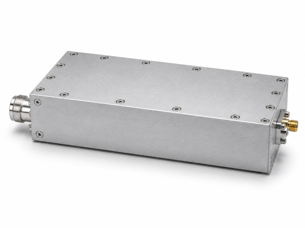
The datasheet lists a frequency range of 500 MHz to 2,000 MHz and 25 W rated output power. Gain is specified at 44 dB minimum, and gain flatness is listed from -3 dB to +3 dB. Gain control range is listed up to 20 dB. Input impedance is 50 ohms with 1.5:1 typical VSWR, and maximum input power is 5 dBm.
The RF input is SMA-Female on the front panel, and the RF output is N-Female on the front panel. Harmonics are listed at -10 dBc typical, and spurious performance is listed at -60 dBc maximum. The control interface is RS485 and LAN. The supply is AC 220 V plus or minus 10 percent at 50/60 Hz, and typical power consumption is 200 W.
Mechanically, the amplifier is listed as a 19-inch 3U rack-mount unit with 16 kg weight and air cooling. The operating temperature range is 0 to +50 C.
How to use it in a test chain
A common setup places a signal generator or vector signal source at the input, followed by attenuation or leveling control, then the amplifier, directional coupler, load path, and device under test. Even at 25 W, the downstream path must be rated for the intended frequency, average power, duty cycle, and mismatch conditions.
The 44 dB gain helps when source output is modest, but the 5 dBm input power limit should be respected. If automated software controls the source and amplifier together, the default state should be low drive, amplifier disabled, or otherwise configured to avoid accidental overdrive during startup.
The 20 dB gain control range allows the amplifier to support multiple test levels without changing hardware. However, gain control should be treated as part of a calibrated power plan. The final delivered power should be measured at the relevant reference plane, not inferred from the amplifier setting alone.
Monitoring and protection features
The CRF-PA-500M2000M-25W includes real-time temperature monitoring, real-time current monitoring, alarm and fault protection, over-temperature protection, over-drive protection, load mismatch protection and alarm functions, and over-voltage protection. Optional input power detection and forward or reverse power monitoring can be reviewed.
These features are helpful for long-running test benches where operators may not be watching every sweep. They also provide status information that can be connected to test software, interlock behavior, or maintenance checks. Before integration, teams should request control protocol details and alarm behavior so software can react consistently.
What to include in the RFQ
For a technical review, provide frequency range, target power at the load, waveform type, CW or pulsed use, duty cycle, source output range, required gain control, load VSWR, connector needs, rack layout, airflow, control interface, and any monitoring options. If the amplifier will be used with antennas or chambers, include path loss and mismatch expectations.
If the project has strict mechanical or documentation requirements, state them early. The datasheet notes that mechanical drawings can be supplied for installation reference, and those drawings are best reviewed before rack design is finalized.
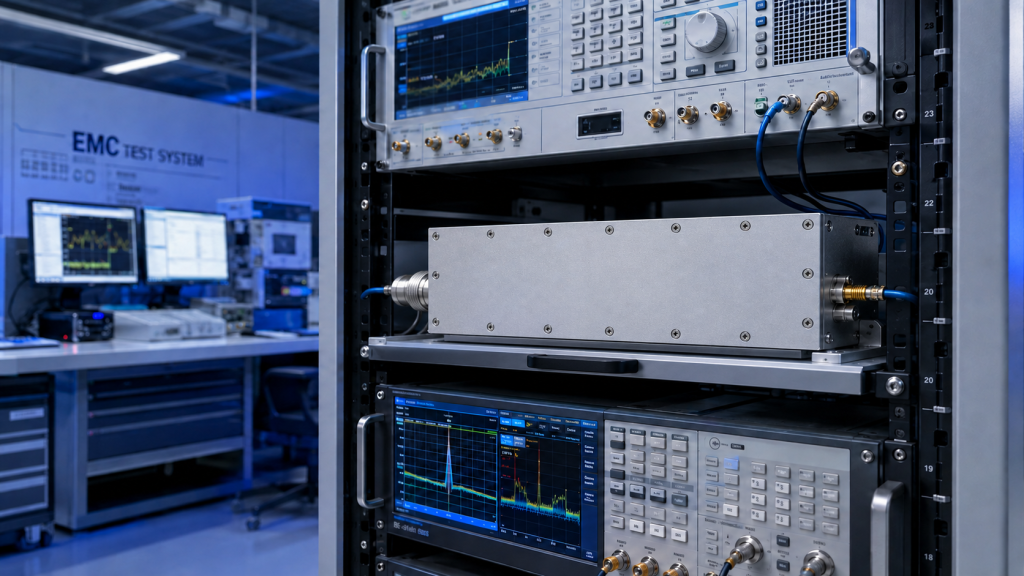
When the amplifier is selected for repeatable bench work, engineers should also document the normal operating envelope: source setting, gain-control value, expected output level, load type, cable assembly, and permitted duty cycle. This small amount of bench documentation prevents accidental changes from being mistaken for amplifier drift.
The 25 W level is also useful for staged development. A team can validate the RF path, software control, and fixture behavior at moderate power before scaling to larger amplifiers. That approach is often cleaner than beginning a new test architecture at the highest available power level.
Frequently Asked Questions
What frequency range does CRF-PA-500M2000M-25W cover?
It covers 500 MHz to 2,000 MHz.
What is the output power?
The amplifier is rated at 25 W RF output power.
What gain does the amplifier provide?
It provides 44 dB minimum gain with up to 20 dB gain control.
What connectors are used?
The RF input is SMA-Female, and the RF output is N-Female.
What is the typical power consumption?
The datasheet lists 200 W typical power consumption.
CTA: Contact CorelixRF to request a compact-power broadband RF amplifier review for 500-2000 MHz testing.