
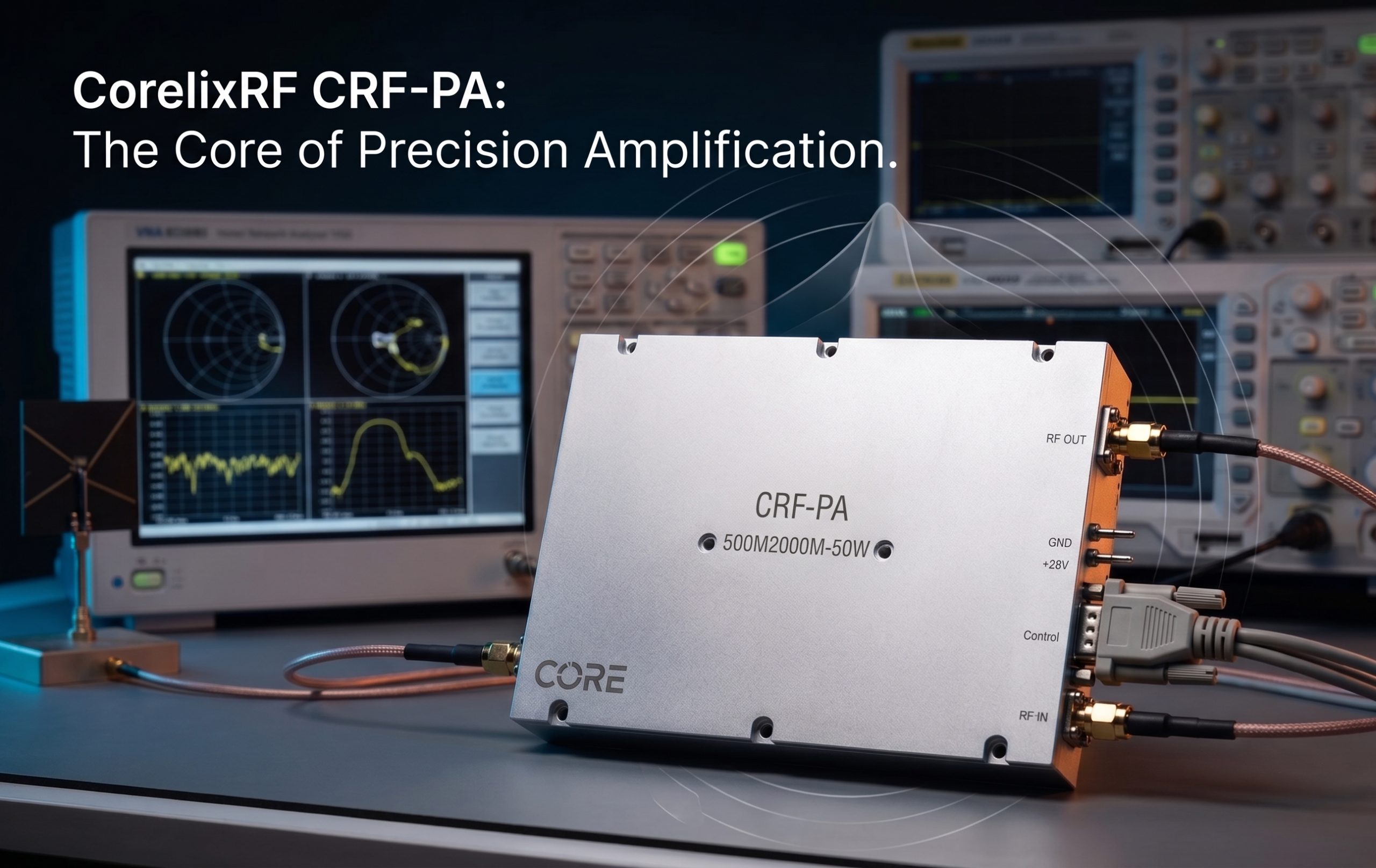
CorelixRF CRF-PA-500M2000M-50W is a 500 MHz to 2,000 MHz GaN solid-state RF power amplifier rated at 50 W output power. It is a practical option when a test bench needs more power than a driver amplifier, but does not require a 100 W, 125 W, or higher-power system. The model includes 47 dB minimum gain, up to 20 dB gain control, SMA-Female RF input, N-Female RF output, RS485 and LAN control, AC 220 V supply, and a 19-inch 3U air-cooled rack format.
This article focuses on where a 50 W broadband RF amplifier fits, what integration details matter, and how engineers can specify the amplifier without making unsupported assumptions about certification, inventory, or application history.
Why a 50W amplifier can be the right size
Not every broadband RF test system needs the largest available amplifier. A 50 W output level can be a better fit when the device under test, antenna path, fixture, or chamber input has moderate power requirements. It can also reduce unnecessary heat, facility load, and safety complexity compared with a much larger amplifier.
The 500 MHz to 2 GHz range is useful for communication-system testing, RF subsystem validation, broadband receiver work, EMC-oriented test benches, and controlled RF interference studies. This range often involves a mix of coaxial fixtures, antennas, couplers, filters, and loads, so a predictable rack amplifier with remote control can simplify repeatable testing.
For many engineers, the main buying intent is not only 500-2000 MHz RF power amplifier. They are also checking whether the amplifier has enough gain for their source, whether the connector format fits their existing bench, and whether control and protection features can be integrated into automated test software.
CRF-PA-500M2000M-50W specifications
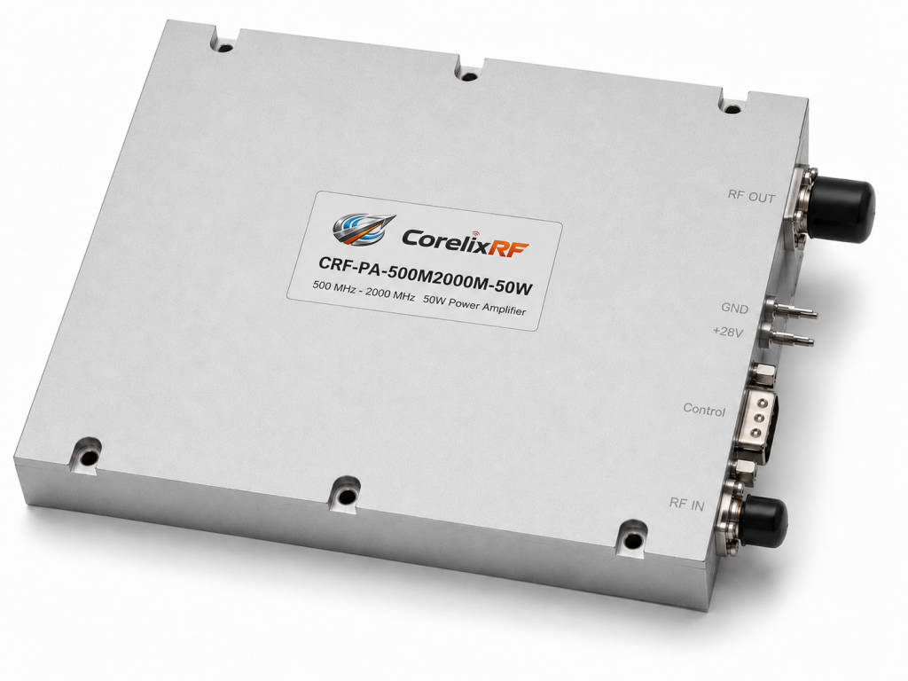
The datasheet lists a frequency range from 500 MHz to 2,000 MHz and 50 W rated output power. Gain is 47 dB minimum, and gain flatness is specified from -3 dB to +3 dB. Gain control range is listed up to 20 dB. Input impedance is 50 ohms with 1.5:1 typical VSWR, and maximum input power is 5 dBm.
The RF input connector is SMA-Female on the front panel, and the RF output connector is N-Female on the front panel. Harmonics are listed at -10 dBc typical, and spurious performance is listed at -60 dBc maximum. The amplifier supports RS485 and LAN control. It operates from AC 220 V plus or minus 10 percent at 50/60 Hz, with typical power consumption of 300 W.
The mechanical format is a 19-inch 3U rack-mount unit with 16 kg listed weight and air cooling. The operating temperature range is 0 to +50 C.
Monitoring and protection for controlled testing
The CRF-PA-500M2000M-50W includes real-time temperature monitoring, real-time current monitoring, alarm and fault protection, over-temperature protection, over-drive protection, over-voltage protection, and load mismatch protection with alarm functions. Optional input power detection and forward or reverse power monitoring can be discussed during project review.
These functions help when the amplifier is used in an automated rack, but they do not replace good system design. The test setup still needs input-level planning, load verification, safe software defaults, RF path confirmation, and appropriate interlocks. Protection is most effective when it works with the system control plan instead of being treated as the only safeguard.
The 20 dB gain control range can help adapt the amplifier to different test levels. Engineers should still calibrate delivered power at the correct reference plane, especially if the output path includes long cables, antennas, chambers, switching matrices, or fixtures.
Connector and rack integration notes
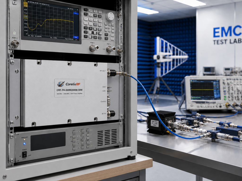
The SMA-Female input is convenient for signal-generator or lower-power RF cabling, while the N-Female output is better suited to the amplifier’s 50 W output level. Integrators should check connector torque, adapter quality, and cable power rating across the full 500 MHz to 2 GHz range.
Because the amplifier is a 3U air-cooled rack unit, airflow and rack spacing should be reviewed before installation. A crowded rack can raise inlet temperature and reduce thermal margin. If the amplifier will run long duty cycles, steady-state rack temperature should be measured rather than assumed.
RS485 and LAN control should be reviewed before software integration. Ask for command documentation, status behavior, alarm handling, enable and disable logic, and any recommended initialization sequence. This avoids improvising control behavior late in the project.
RFQ checklist for this model
An RFQ should include frequency range, output power target, waveform type, CW or pulsed operation, duty cycle, source power, required gain control, load VSWR, connector preferences, rack constraints, control interface, and monitoring requirements. For EMC-style projects, include chamber, antenna, coupler, and field-strength goals if available.
If a standard CRF-PA-500M2000M-50W configuration is close but not exact, state what needs to be reviewed. Connector placement, monitoring options, control details, documentation package, and mechanical drawings can be addressed more efficiently when they are described early.
For teams comparing the 25 W, 50 W, and 125 W versions in the same frequency family, the 50 W model is often the compromise point. It gives more margin than a low-power bench amplifier, but it can still be integrated without treating every test as a high-power facility project. That makes it a sensible candidate when the test requirement is still evolving.
Frequently Asked Questions
What frequency range does CRF-PA-500M2000M-50W cover?
It covers 500 MHz to 2,000 MHz.
What output power does this model provide?
The datasheet lists 50 W rated RF output power.
What is the minimum gain?
The amplifier provides 47 dB minimum gain.
What control interfaces are available?
RS485 and LAN control are listed.
What is the mechanical format?
It is a 19-inch 3U rack-mount amplifier with air cooling.
CTA: Contact CorelixRF to discuss a 500-2000 MHz 50W RF power amplifier for your test bench.