
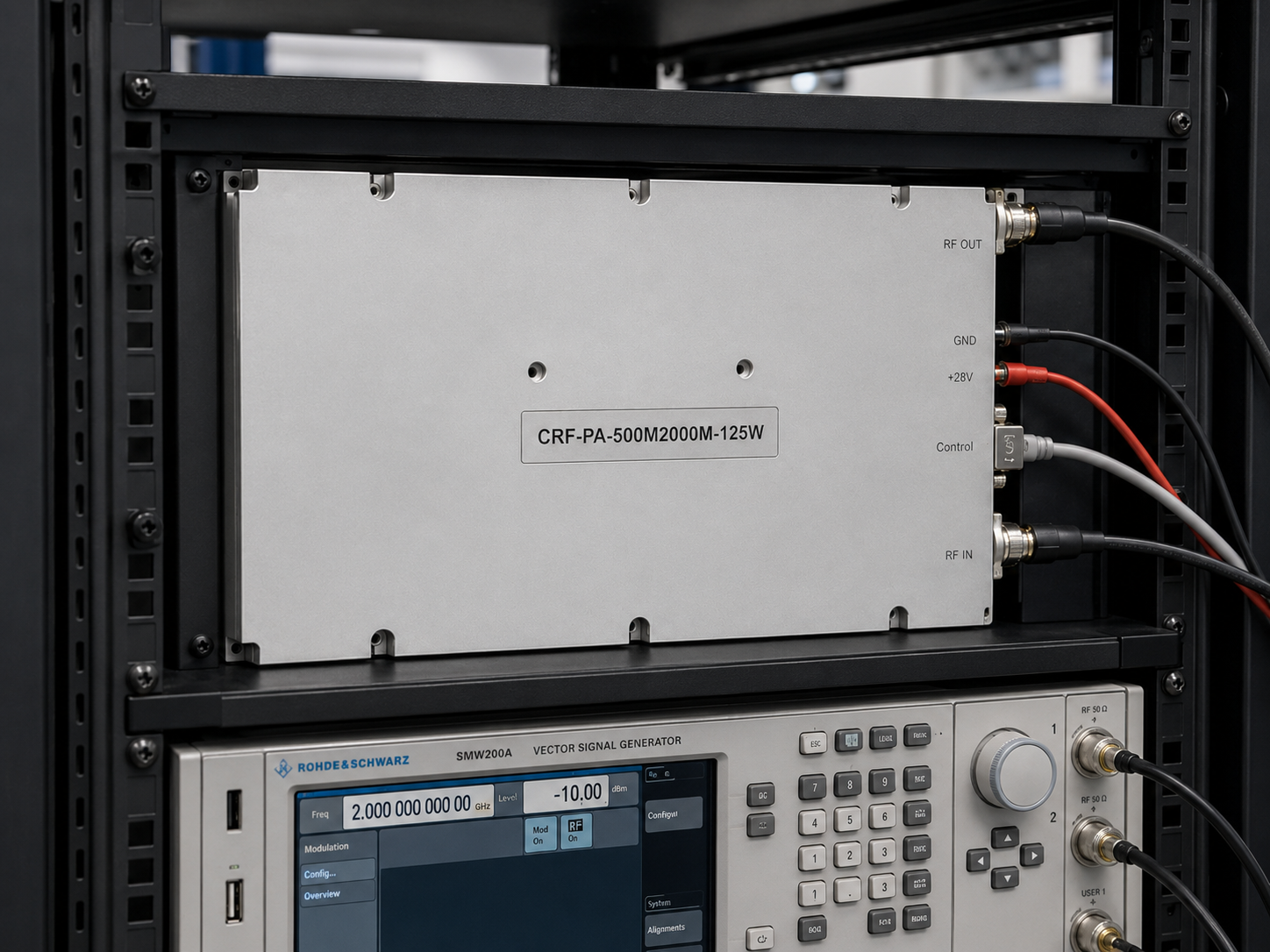
CorelixRF CRF-PA-500M2000M-125W is a 500 MHz to 2,000 MHz GaN solid-state RF power amplifier rated at 125 W output power. It is built for engineering teams that need a controlled broadband RF power stage across the upper UHF and L-band region, with enough output power for EMC-style test benches, communication-system validation, RF interference system-level testing, and aerospace-control related RF paths.
The useful question is not only whether the amplifier can make 125 W. Engineers also need to know whether the gain, connectors, control interface, cooling method, and protection behavior fit the test environment. This model combines 50 dB minimum gain, up to 20 dB gain control, SMA-Female RF input, N-Female RF output, RS485 and LAN control, AC 220 V operation, and a 19-inch 3U air-cooled rack format.
Why 500-2000 MHz coverage is useful
The 500 MHz to 2 GHz range sits in a busy part of the RF spectrum. It overlaps many practical laboratory needs, including communication equipment evaluation, broadband receiver testing, RF immunity work, subsystem stress testing, antenna-path checks, and general RF test and measurement. A single amplifier covering this range can reduce the need to swap narrowband amplifiers when a test plan crosses multiple bands.
For EMC and immunity-oriented systems, the amplifier must be predictable over frequency. Fixture loss, cable loss, antenna efficiency, coupler response, and chamber behavior can all change across this range. A broadband amplifier with 125 W output power gives the test engineer usable margin, but the final delivered power still depends on the complete RF path.
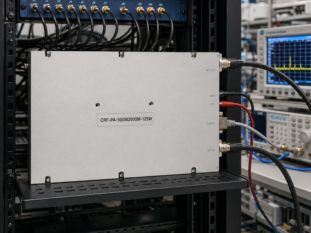
CRF-PA-500M2000M-125W key specifications
The datasheet lists a frequency range of 500 MHz to 2,000 MHz and 125 W rated output power. Gain is specified at 50 dB minimum, with gain flatness from -3 dB to +3 dB. Gain control range is listed up to 20 dB. Input impedance is 50 ohms with 1.5:1 typical VSWR, and maximum input power is 5 dBm.
The amplifier uses an SMA-Female input connector on the front panel and an N-Female output connector on the front panel. Control is available through RS485 and LAN. The supply is AC 220 V plus or minus 10 percent at 50/60 Hz, with typical power consumption of 600 W. The mechanical format is a 19-inch 3U rack-mount unit with 16 kg typical weight and air cooling.
The platform includes real-time temperature monitoring, real-time current monitoring, alarm and fault protection, over-temperature protection, over-drive protection, over-voltage protection, and load mismatch protection with alarm functions. Optional input power detection and forward or reverse power monitoring can be reviewed for project needs.
Integration notes for RF test benches
The 50 dB gain figure makes the amplifier convenient when source power is limited, but it also makes input-level discipline important. Automated benches should include source limits, attenuation planning, safe default states, and interlock logic so the amplifier is not overdriven. The 5 dBm maximum input power should be treated as a hard integration constraint.
The output path should be reviewed for power handling and mismatch tolerance. At 125 W, adapters, switches, couplers, cables, feedthroughs, attenuators, and loads need to be chosen for the operating frequency range and expected duty cycle. If an antenna or chamber is used, reflected-power behavior should be part of the test plan.
Rack installation is straightforward in concept but still deserves attention. The amplifier uses air cooling, so airflow must not be blocked by neighboring equipment. Rack planners should allow service access, front-panel cable clearance, and a clean control path for RS485 or LAN commands.
What engineers should verify before first power-on
Before applying RF drive, engineers should verify the source output limit, attenuation state, load connection, output cable rating, and control status. The amplifier should be brought up with a known load and a conservative drive level before it is connected to a more complex fixture, antenna, or chamber path. This first-power-on discipline is especially useful when several people share the same RF bench.
A second useful check is the delivered-power reference plane. The amplifier output power is only one part of the test budget. If the measurement point is after a coupler, long cable, switch matrix, antenna feed, or chamber input, frequency-dependent loss can change the delivered level. Recording that loss table early makes later test data easier to defend.
How to prepare a useful RFQ
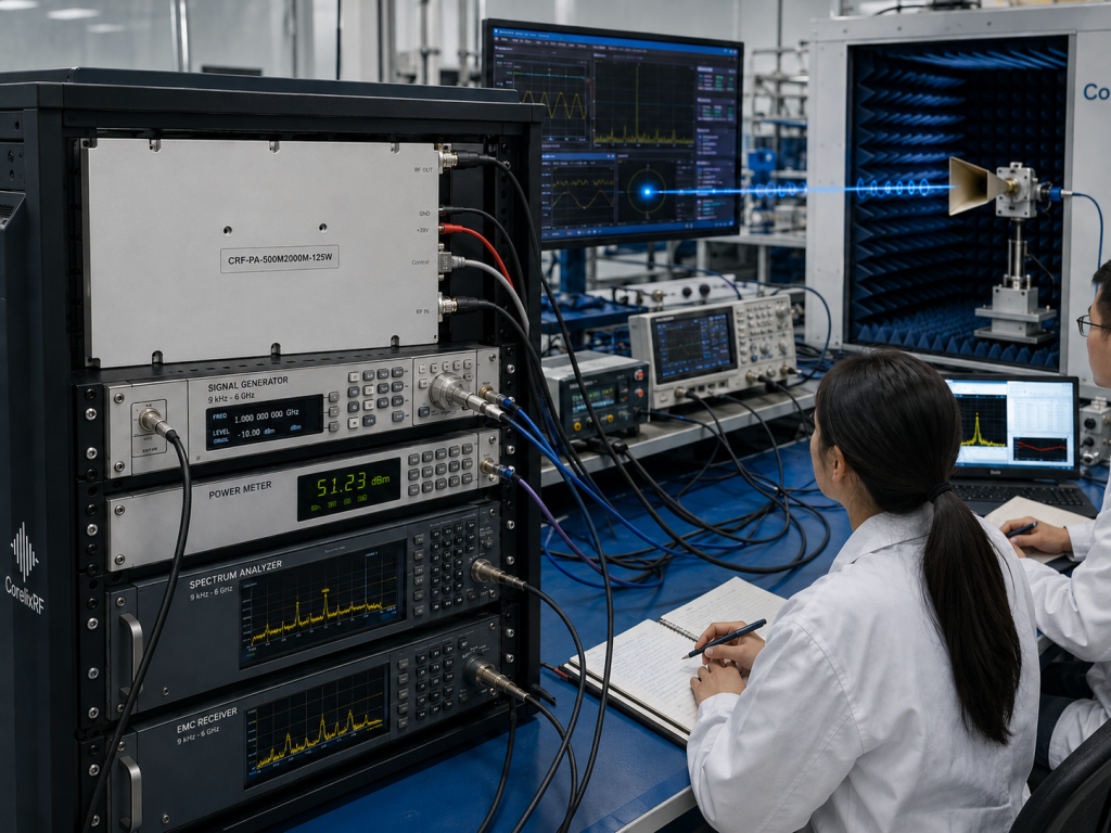
A strong RFQ should include the required frequency range, target output power at the load, waveform type, duty cycle, input drive level, control interface, cooling environment, rack limitations, expected load VSWR, and monitoring requirements. If the amplifier will be used in EMC-style testing, include antenna, chamber, fixture, and coupler information where available.
For CorelixRF review, also state whether the 3U rack format is acceptable, whether LAN control is required, and whether input power detection or forward and reverse power monitoring should be included. These details help the technical team review the amplifier as part of a complete RF path rather than as an isolated wattage number.
Frequently Asked Questions
What frequency range does CRF-PA-500M2000M-125W cover?
It covers 500 MHz to 2,000 MHz.
What output power is rated for this amplifier?
The datasheet lists 125 W RF output power.
What gain is specified?
The amplifier provides 50 dB minimum gain with up to 20 dB gain control.
What RF connectors are used?
The RF input is SMA-Female, and the RF output is N-Female.
What protection features are included?
The platform includes temperature, current, over-drive, over-voltage, and load mismatch protection or alarm functions.
CTA: Contact CorelixRF to request a 500-2000 MHz RF amplifier review for your EMC or broadband test project.