
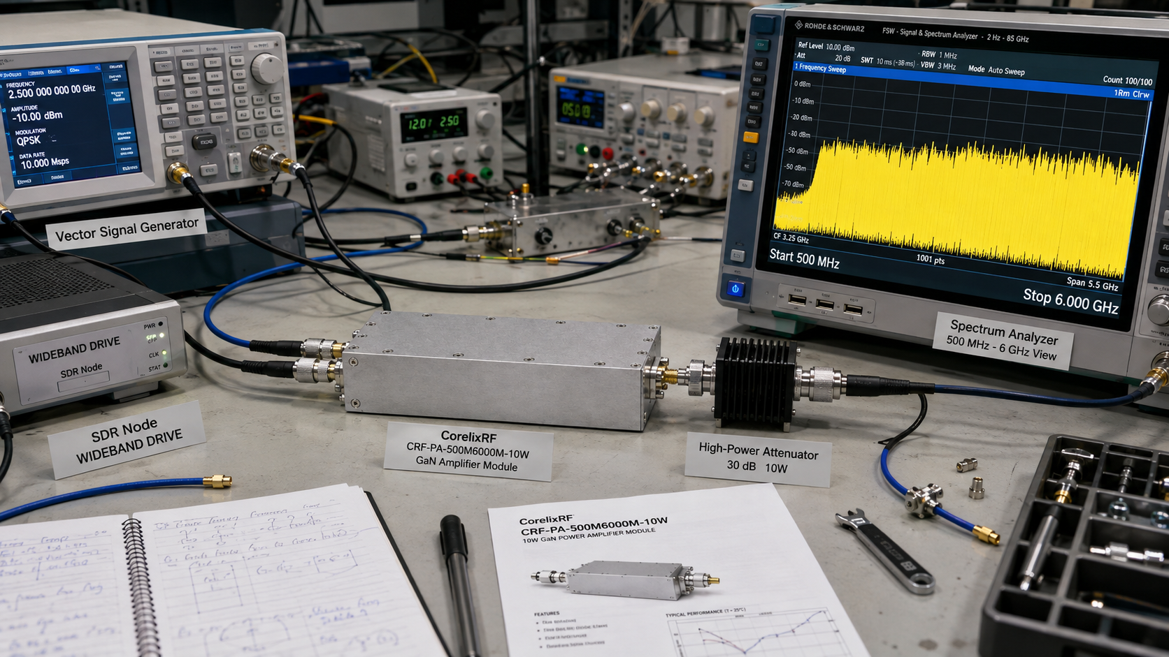
CorelixRF CRF-PA-500M6000M-10W is a compact broadband GaN RF amplifier module operating from 0.5 GHz to 6 GHz with 10 W rated output power. It is built for projects where engineers need wide frequency coverage, moderate RF output, DC-powered module integration, and control access without committing to a rack-mounted amplifier.
The datasheet lists 40 dB minimum gain, SMA-Female input and output connectors, CAN control, DC 28 V supply, 130 x 85 x 25 mm mechanical size, and conduction or system-level cooling according to the installation. The platform also includes real-time temperature and current monitoring, alarm protection, over-temperature protection, over-drive protection, over-voltage protection, and VSWR protection or alarm functions.
Why 0.5-6 GHz coverage is valuable
A 0.5 GHz to 6 GHz amplifier covers a wide portion of common RF development work. It bridges upper UHF, L-band, S-band, and C-band related test needs in one module. That makes it useful for broadband receiver testing, SDR-related RF chains, communication subsystem validation, compact RF interference test setups, and general laboratory power boosting.
The 10 W output level is useful when the amplifier is acting as a moderate-power stage rather than the final high-power source. It can help overcome fixture loss, cable loss, switch loss, or antenna path loss while keeping power, heat, and mechanical size manageable. This is especially important in embedded systems, portable test equipment, and custom RF subsystems.
Module-level integration gives engineers flexibility, but it also pushes thermal and mechanical responsibility into the final system. The CRF-PA-500M6000M-10W should therefore be specified with the enclosure, heat path, RF cabling, DC supply, grounding, control interface, and operating environment in mind.
CRF-PA-500M6000M-10W specifications
The amplifier operates from 0.5 GHz to 6 GHz and is rated for 10 W output power. Minimum gain is 40 dB, with gain flatness from -4 dB to +4 dB. Maximum input power is 0 dBm. Input impedance is 50 ohms, and input VSWR is listed as 2:1 maximum.
RF input and output connectors are SMA-Female. Harmonics are listed at -10 dBc maximum, and spurious performance is listed at -60 dBc maximum. The control interface is CAN. The power supply is DC 28 V. The mechanical size is 130 x 85 x 25 mm, and the operating temperature range is 0 to +50 C.
The datasheet describes cooling as conduction or system-level cooling per installation. That wording is important: the module needs a suitable thermal path designed into the host system, not a generic assumption that open-air operation will be enough under all duty cycles.
Design considerations for compact systems
The first integration topic is thermal design. A 10 W RF output module still dissipates meaningful heat, especially over broadband operation. The mounting surface, enclosure material, airflow, duty cycle, ambient temperature, and nearby heat sources should be reviewed before the mechanical design is frozen.
The second topic is DC power. The 28 V supply should be stable, adequately rated, and protected. If the module is part of a larger system with other RF electronics, power sequencing and grounding should be checked to avoid control errors, noise coupling, or accidental RF drive during startup.
The third topic is RF drive control. With 40 dB minimum gain and 0 dBm maximum input power, engineers should include attenuation, source limits, and safe software defaults. If the amplifier is driven by an SDR, upconverter, or signal generator, the source output range should be verified across all operating modes.
Where the module fits best
The CRF-PA-500M6000M-10W is a good candidate for compact broadband RF test sets, custom instrumentation, embedded RF subsystems, low-to-moderate power communication test chains, and pre-compliance style experimentation where broad coverage is more important than very high output power.
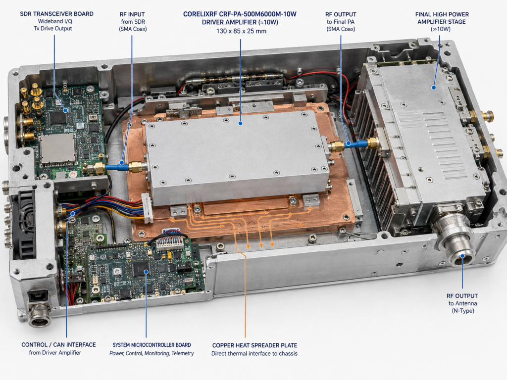
It can also act as a driver stage for systems that later feed a higher-power amplifier, provided the downstream amplifier input requirement is compatible. In that case, the key parameters are output level, flatness, noise behavior, and protection coordination between stages.
What to provide for a CorelixRF review
Engineers should provide the target frequency range, desired output power at the load, waveform type, duty cycle, input drive level, DC supply details, enclosure constraints, thermal path, control-interface needs, and monitoring requirements. If the module will be installed in a portable or embedded system, include shock, vibration, airflow, connector orientation, and service constraints if they matter.
If forward or reverse power monitoring, input power detection, or a programmable control interface is required, state that in the initial RFQ. These options are easier to evaluate before the host mechanical and control design is locked.
A practical module review should also include the maintenance plan. If the amplifier is buried deep inside a custom enclosure, service access, connector replacement, thermal-interface inspection, and firmware or control troubleshooting become harder. Leaving a little mechanical intelligence around the module can save time later.
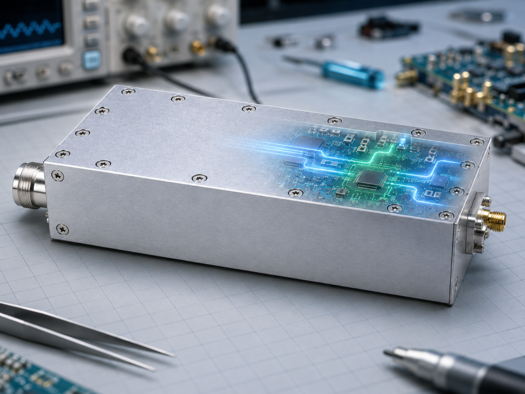
Engineers should also decide whether the module is a final output stage or a driver stage. As a final stage, the downstream load and delivered power are the priority. As a driver, gain stability, output range, and compatibility with the next amplifier input become more important. The same hardware can be sensible in either role, but the review questions are different.
Frequently Asked Questions
What frequency range does CRF-PA-500M6000M-10W cover?
It covers 0.5 GHz to 6 GHz.
What output power is rated?
The amplifier is rated at 10 W RF output power.
What is the gain?
The datasheet lists 40 dB minimum gain.
What control interface does it use?
The listed control interface is CAN.
What is the module size?
The datasheet lists 130 x 85 x 25 mm.
CTA: Contact CorelixRF to review a compact 500 MHz-6 GHz RF amplifier module for your system.