
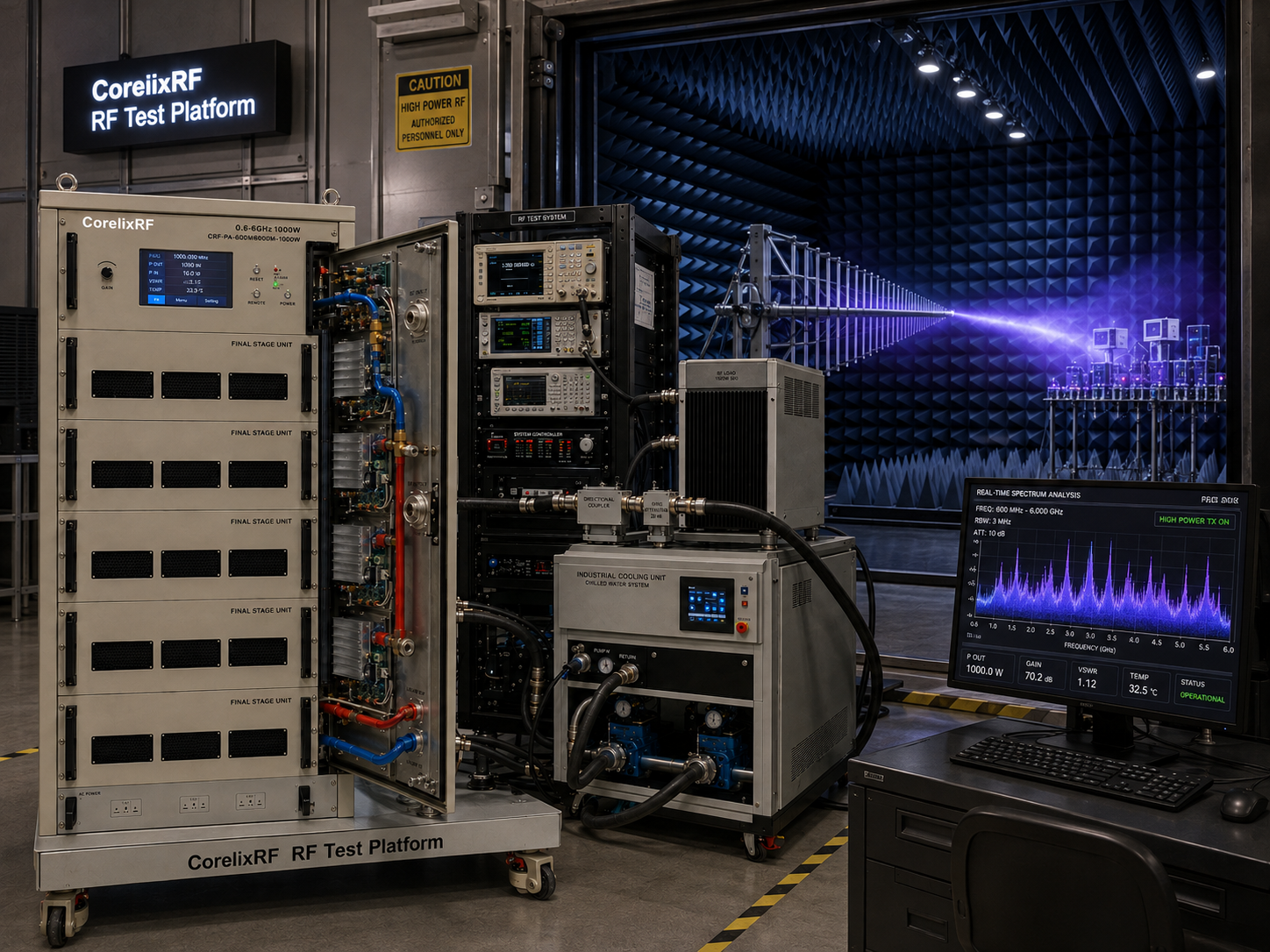
CorelixRF CRF-PA-600M6000M-1000W is a 600 MHz to 6,000 MHz GaN solid-state RF power amplifier rated at 1000 W output power. It is a high-power broadband platform for demanding RF test systems, communication-system validation, RF interference or EW system-level testing, and aerospace-control related RF paths where wide coverage and substantial RF power are required.
This is a system-level amplifier. At 1000 W across 600 MHz to 6 GHz, the amplifier cannot be specified by frequency and wattage alone. Engineers must review the RF path, facility power, liquid cooling, reflected-power behavior, control interface, protection logic, interlocks, and test safety before integration. The datasheet lists 63 dB minimum small-signal gain, N-Female input, 7/16 output, RS485 and LAN control, AC 380 V supply, project-specific mechanical configuration, and liquid cooling.
Why 600 MHz-6 GHz at 1000W is demanding
The 600 MHz to 6 GHz range spans a large part of practical RF testing. It reaches from upper-UHF and L-band related work through S-band and C-band related microwave tests. A single broadband amplifier in this range can support multi-band validation without changing amplifier hardware between bands.
The 1000 W output level adds serious system responsibility. Every output-side component must be reviewed for power handling, frequency range, average power, connector rating, mismatch behavior, and thermal dissipation. Cables, adapters, directional couplers, switches, attenuators, loads, antennas, and chamber interfaces all become critical parts of the amplifier system.
Liquid cooling helps manage heat, but it also introduces facility and maintenance considerations. Coolant type, flow, pressure, inlet temperature, fittings, leak management, and shutdown behavior should be reviewed before the amplifier is installed.
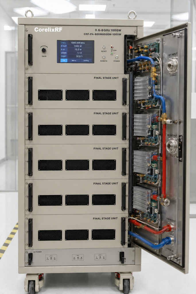
CRF-PA-600M6000M-1000W specifications
The datasheet lists a frequency range of 600 MHz to 6,000 MHz and 1000 W output power. Small-signal gain is 63 dB minimum, with gain flatness from -5 dB to +5 dB. Maximum input power is 0 dBm. Input impedance is 50 ohms, with 2:1 maximum VSWR listed.
The RF input connector is N-Female, and the RF output connector is 7/16. Harmonics are listed at -10 dBc maximum, and spurious performance is listed at -60 dBc maximum. The control interface is RS485 and LAN. The power supply is AC 380 V plus or minus 10 percent.
The mechanical form factor is project-specific, and the cooling method is liquid cooling. The operating temperature range is 0 to +50 C. Monitoring includes real-time temperature monitoring and real-time current monitoring. Optional forward or reverse power monitoring and LAN remote monitoring can be reviewed. Protection functions include alarm and fault protection, over-temperature protection, over-drive protection, over-voltage protection, and VSWR protection or alarm functions.
Integration planning for high-power broadband systems
A 1000 W broadband RF amplifier should be integrated with a formal signal-chain plan. The input path must prevent overdrive, especially because 63 dB gain can produce high output from modest source levels. Fixed attenuation, programmable attenuation, source limits, safe startup defaults, and software interlocks should all be considered.
The output path should be designed around worst-case frequency, duty cycle, and mismatch. The 7/16 output connector supports high-power RF handling, but the rest of the system must be matched to the same standard. Engineers should also consider how reflected power will be detected, reported, and handled by the test sequence.
Liquid cooling should be treated as a subsystem. The amplifier should not be enabled unless cooling readiness is confirmed. If the facility cooling loop has alarms, those alarms should be tied into the system control plan. A high-power amplifier is happiest when the entire installation behaves predictably.
Calibration and delivered power
The output rating identifies amplifier capability, but the test requirement is usually delivered power at a device, antenna, chamber input, or field point. Delivered power depends on cable loss, coupler loss, adapter loss, switch loss, fixture loss, frequency response, and mismatch.
For broadband sweeps, engineers should create a calibration table or leveling strategy across frequency. The amplifier gain flatness is only one part of the total path response. Without system-level calibration, a test may appear to use constant source settings while actually delivering very different power at different frequencies.
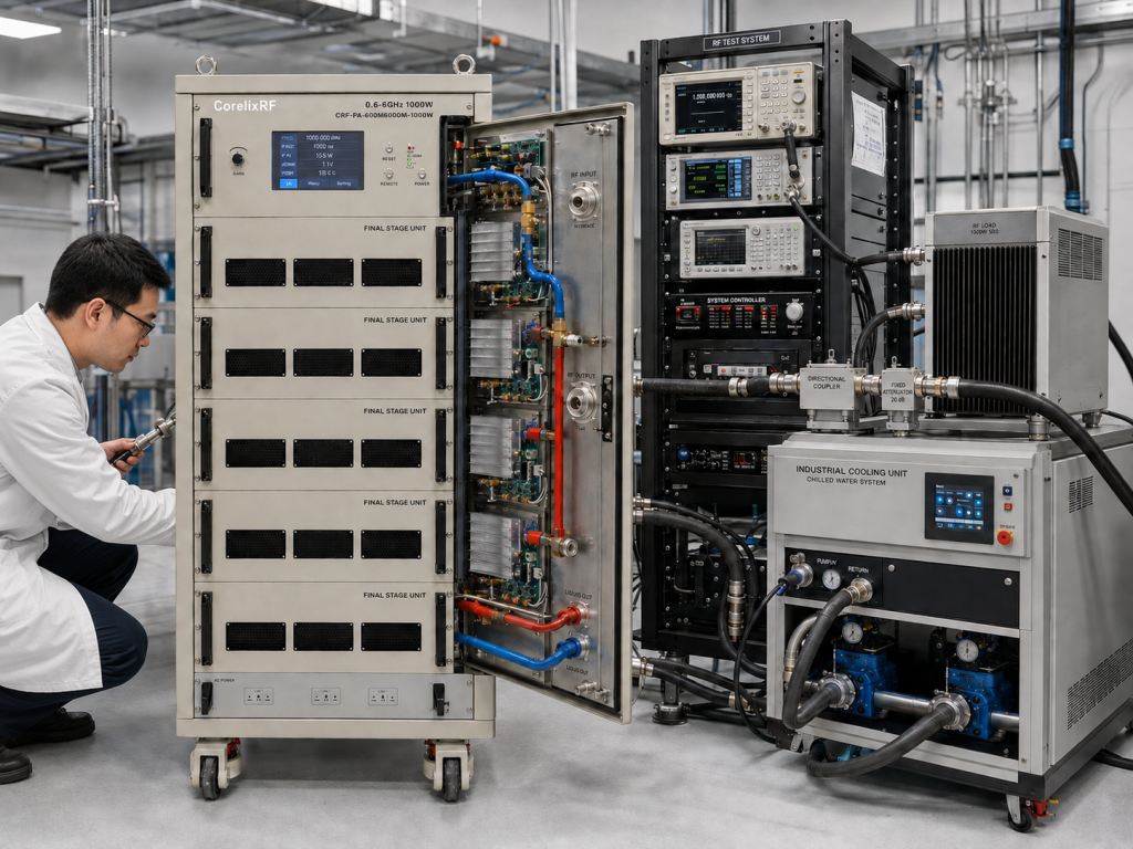
RFQ checklist for this amplifier
A CorelixRF RFQ should include target frequency range, required output power at the load, waveform type, CW or pulsed operation, duty cycle, expected load VSWR, source drive level, control interface, monitoring requirements, AC power availability, liquid-cooling facility details, mechanical constraints, rack or cabinet plan, and documentation needs.
If the system will use antennas, chambers, field probes, or long cable runs, include those details. If forward and reverse power monitoring or LAN remote monitoring is required, state that early. For a 1000 W broadband amplifier, early clarity saves painful redesign later.
Operational procedures should also be part of the purchase discussion. A high-power liquid-cooled amplifier benefits from written startup, shutdown, fault recovery, and cooling-readiness steps. If multiple operators use the system, those procedures reduce variation and make it easier to separate amplifier behavior from test setup changes.
Spare adapters and verified loads are worth planning as well. At this power level, a questionable adapter or underrated load is not a small nuisance; it can become the weak point in the test chain. Treating the RF accessories as part of the amplifier system is the boring choice, and in high-power RF, boring is often exactly what good engineering looks like.
Frequently Asked Questions
What frequency range does CRF-PA-600M6000M-1000W cover?
It covers 600 MHz to 6,000 MHz.
What output power is rated?
The datasheet lists 1000 W RF output power.
What gain is specified?
The amplifier provides 63 dB minimum small-signal gain.
What RF connectors are used?
The RF input is N-Female, and the RF output is 7/16.
What cooling method is listed?
The amplifier uses liquid cooling with project-specific mechanical configuration.
CTA: Contact CorelixRF to discuss a 600 MHz-6 GHz 1000W liquid-cooled GaN SSPA for high-power RF testing.