
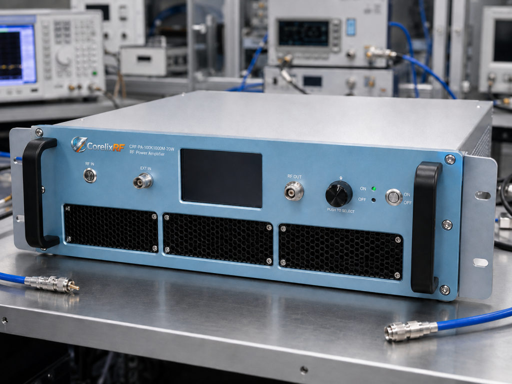
The CRF-PA-100K1000M-20W is a 100 kHz to 1 GHz RF power amplifier designed for engineers who need moderate solid-state RF output power across a very wide low-frequency to UHF span. Based on the supplied CorelixRF datasheet, it is a 20 W LDMOS SSPA in a forced-air 19-inch 3U rack-mount configuration with N-Female RF input and output connectors.
For buyers comparing a broadband RF power amplifier for EMC, RF interference, communications, and instrumentation benches, this model fills the gap between small driver amplifiers and high-power rack systems. It supports project-ready RS485 / LAN control options, real-time temperature and current monitoring, and built-in alarm protection functions that help simplify integration into a controlled RF rack.
Why choose a 100 kHz to 1 GHz RF power amplifier?
A 100 kHz to 1 GHz RF power amplifier is useful when one test platform must cover low-frequency RF, VHF, and UHF work without changing amplifier chains. EMC pre-compliance, RF susceptibility evaluation, communication equipment testing, aerospace control-system support, and wideband signal simulation can all benefit from a single amplifier that covers this span.
The CRF-PA-100K1000M-20W is specified for 20 W minimum output power and 45 dB minimum small-signal gain. That combination gives test engineers enough gain to drive many lab signal sources into usable RF power levels while keeping the output level manageable for bench and chamber setups. The listed gain flatness is -3 to +3 dB, with up to 20 dB gain control range.
This model is especially relevant when a project needs a custom RF amplifier rather than a one-size-fits-all catalog unit. Frequency coverage, control protocol, forward/reverse power monitoring, and GPIB or LAN-related functions can be reviewed at the project level where applicable.
Core specifications for CRF-PA-100K1000M-20W
The datasheet identifies the amplifier as an LDMOS SSPA with 50 ohm system impedance. Its frequency range is 100 kHz to 1,000 MHz, rated output power is 20 W, and small-signal gain is 45 dB minimum. Input power is listed at 0 dBm maximum, harmonics at -10 dBc maximum, and spurious response at -60 dBc maximum.
RF input and output use N-Female connectors. The supply is AC 220 V +/-10%, 50/60 Hz, with typical power consumption of 400 W. The unit is built as a 19-inch 3U rack-mount amplifier with forced-air cooling and an operating temperature range from 0 to +50 C. Typical weight is listed as 20 kg.
These details matter for engineers designing a rack-mount RF amplifier into a test system because the amplifier is not only an RF block. It also needs rack space, AC power planning, airflow clearance, cabling access, monitoring integration, and a defined safety response when the RF path is mismatched or overdriven.
Protection and monitoring for EMC and RF interference benches
EMC and RF interference testing can expose an amplifier to changing loads, operator adjustments, and aggressive test schedules. The CRF-PA-100K1000M-20W includes real-time temperature monitoring, real-time current monitoring, alarm and fault protection, over-temperature protection, over-drive protection, over-voltage protection, and VSWR protection with alarm functions.
Forward and reverse power monitoring are identified as optional, and LAN remote monitoring can also be reviewed as an option. These functions are valuable in test automation because they give the system integrator signals that can be used for interlocks, test sequencing, and fault handling. A controlled EMC RF amplifier should not depend only on the operator watching the front panel.
Where this amplifier fits in an RF test architecture
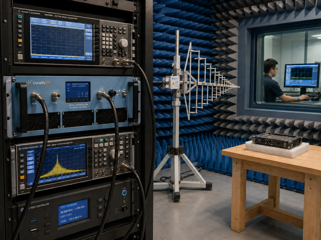
The 20 W rating makes the CRF-PA-100K1000M-20W a practical choice for moderate-power broadband RF work. It can support test and measurement instrumentation, communication systems, RF interference / EW system-level testing, and aerospace control systems, according to the datasheet.
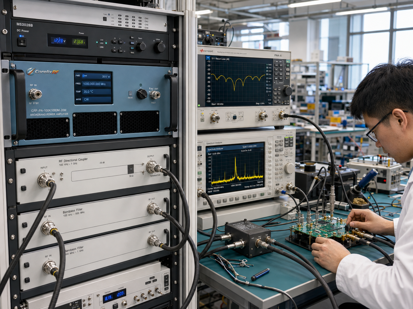
In a typical setup, a signal generator or SDR source feeds the amplifier input through appropriate attenuation and filtering. The amplifier output then feeds a load, antenna, coupler, test chamber, or fixture. Engineers should confirm input drive, duty cycle, waveform type, expected mismatch conditions, cable loss, and whether the final application requires CW, pulsed, modulated, or swept-frequency operation.
When the test span reaches from 100 kHz to 1 GHz, fixture behavior can change dramatically across the range. Cable selection, coupler bandwidth, antenna efficiency, and measurement receiver dynamic range all deserve review before the amplifier is specified. CorelixRF can help evaluate whether the CRF-PA-100K1000M-20W or another RF power amplifier configuration is the better match.
Questions to resolve before quotation
Before requesting a quotation, prepare the target frequency range, required output power at the load, waveform type, CW or pulse operation, duty cycle, control interface, mechanical constraints, and environmental requirements. If the amplifier will be used in an automated EMC or RF interference bench, include the desired remote control method and fault reporting expectations.
The datasheet notes that final mechanical drawing, test data, and control protocol can be supplied for project review where applicable. That makes the model suitable for technical procurement teams that need more than a price quote; they need a documented path to system integration.
FAQ
What is the frequency range of the CRF-PA-100K1000M-20W?
The specified frequency range is 100 kHz to 1,000 MHz, covering low-frequency RF through VHF and UHF bands.
How much RF output power does this amplifier provide?
The datasheet lists 20 W rated solid-state RF output power.
What RF connectors are used?
The amplifier uses N-Female RF input and N-Female RF output connectors.
Is remote monitoring available?
The datasheet lists RS485 / LAN control interface support, with optional LAN remote monitoring and optional forward/reverse power monitoring where applicable.
What should I provide for a technical review?
Provide frequency range, output power, waveform type, duty cycle, control requirements, mechanical limits, cooling constraints, and environmental conditions.