
The CRF-PA-20M1000M-100W is a 20 MHz to 1 GHz GaN RF amplifier module for projects that need 100 W solid-state RF output power in a compact mechanical format. The supplied CorelixRF datasheet identifies it as a broadband SSPA using GaN technology, with N-Female RF input and output connectors, RS485 control, and a 250 x 120 x 30 mm module configuration.
For engineers comparing a GaN RF amplifier for SDR, communication, RF interference, or test instrumentation work, this model offers a practical blend of bandwidth, power, and integration flexibility. It is not a rack amplifier by default; it is a module intended to be mounted with an external heatsink and forced-air cooling.
What makes a 20 MHz to 1 GHz GaN RF amplifier useful?
A 20 MHz to 1 GHz GaN RF amplifier covers many low-VHF, VHF, UHF, and wideband communication test requirements. The CRF-PA-20M1000M-100W is specified for 100 W rated output power and 50 dB minimum small-signal gain. That gain level helps lift common lab signal-generator or transceiver-level signals into a power range suitable for system testing, fixture driving, and controlled RF evaluation.
Its 20 dB typical gain adjustment range is useful when the same amplifier must support multiple test cases. Engineers can reduce gain for sensitive DUTs, increase gain for higher power paths, or integrate gain control into automated test routines. For a broadband RF power amplifier used across many waveforms, adjustable gain often matters as much as headline output power.
Key specifications of CRF-PA-20M1000M-100W
The amplifier covers 20 MHz to 1 GHz and is rated for 100 W output power. Small-signal gain is 50 dB minimum, gain flatness is listed as -4 to +4 dB, and typical gain adjustment range is 20 dB. The datasheet lists maximum input power as 0 dBm, harmonic performance at -10 dBc maximum, spurious at -60 dBc maximum, and input impedance / VSWR as 50 ohm / 1.6:1 maximum.
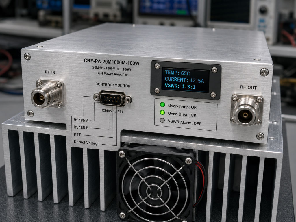
RF input and output connectors are N-Female. The supply is DC 36 V, with the interface table listing +28 to +40 V DC and nominal +36 V through a 4-pin aviation connector. Control is provided through RS485, and the DB9 interface includes PTT, attenuation control voltage, input detection voltage, forward detection voltage, reverse detection voltage, temperature detection voltage, and ground pins.
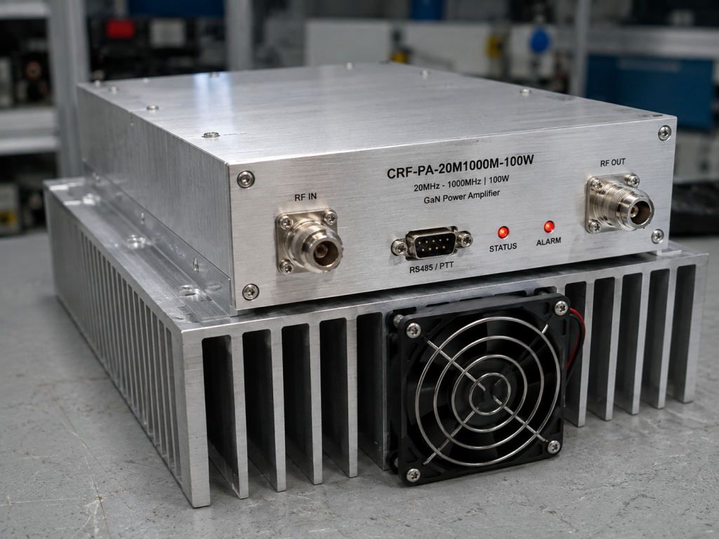
The mechanical size is 250 x 120 x 30 mm. Cooling is external heatsink forced-air cooling. That makes thermal design a shared responsibility between the amplifier module and the system enclosure. If the final system has limited airflow, confirm heatsink mass, fan performance, ambient temperature, duty cycle, and mounting method before finalizing the custom RF amplifier configuration.
Integration advantages for SDR and communication systems
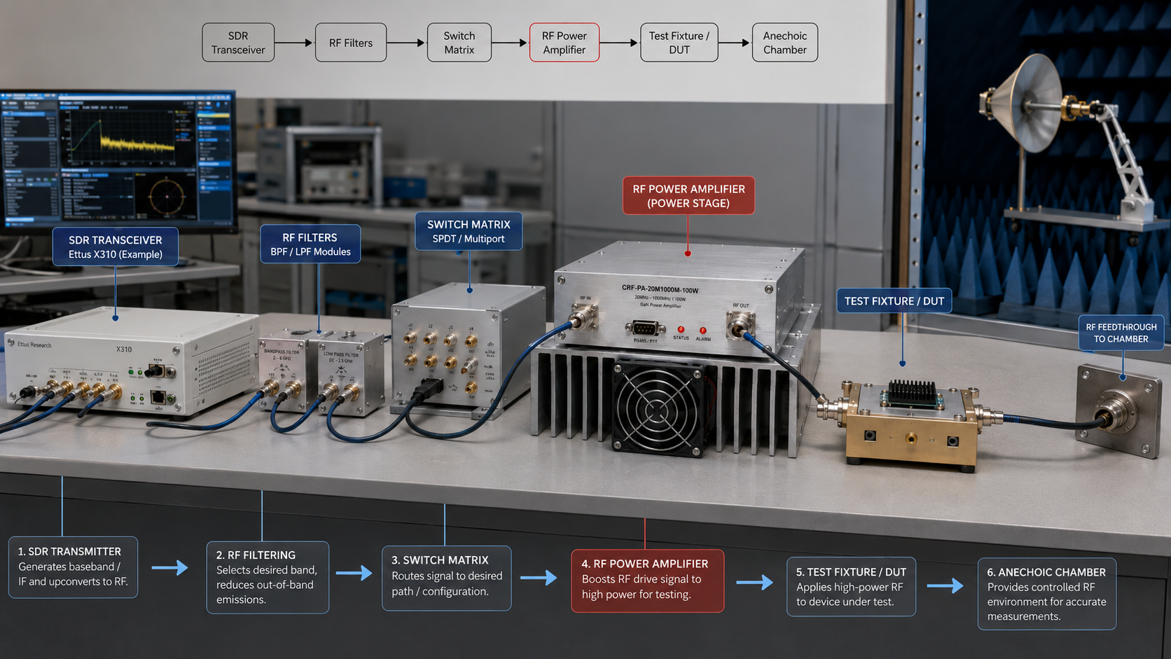
The CRF-PA-20M1000M-100W is relevant to SDR and communication testing because it can cover a broad frequency range while keeping a compact module footprint. In an SDR chain, it may be used after a driver stage, attenuator, filter bank, or switch matrix. In communication equipment testing, it can support banded or swept evaluations across a wide RF span.
The datasheet lists primary applications including test and measurement instrumentation, communication systems, RF interference system-level testing, and aerospace control systems. Those applications benefit from the amplifier’s combination of GaN power density, RS485 control, gain adjustment, and monitoring signals. A module-level SDR RF amplifier must be easy to enable, disable, monitor, and reset without physically accessing the RF enclosure.
Protection and diagnostic signals
Protection functions include alarm and fault protection, over-temperature protection, over-drive protection, over-voltage protection, and VSWR protection with alarm functions. The amplifier also supports real-time temperature monitoring and real-time current monitoring. Optional RF input, forward, and reverse detection interfaces are listed for project configurations.
These features help system designers build safer RF equipment. A high-gain 100 W amplifier can be damaged or can damage downstream components if the RF path is mismatched, overdriven, or overheated. When selecting any RF power amplifier, the monitoring and control strategy should be reviewed together with RF performance.
Procurement and design review notes
Before requesting a quotation, define the operating band, required output power at the system load, modulation type, CW or pulsed operation, duty cycle, available DC supply, cooling envelope, control interface, and whether forward/reverse detection outputs are required. Because the module uses external heatsink forced-air cooling, mechanical and thermal information should be included early.
CorelixRF can review built-in coupler options, RF detector outputs, gain adjustment, control interface, and mechanical details according to project requirements. This is useful when the amplifier is going into a finished product, transportable system, or lab fixture where connector position and heat flow matter.
FAQ
What is the rated output power of CRF-PA-20M1000M-100W?
The datasheet lists 100 W rated solid-state RF output power.
What frequency range does this amplifier cover?
It covers 20 MHz to 1 GHz.
Is this a rack-mount amplifier?
No. The datasheet lists a compact 250 x 120 x 30 mm module configuration requiring external heatsink forced-air cooling.
What control interface is available?
The amplifier uses RS485 control, with DB9 pins for serial bus, PTT, attenuation control, detection voltages, and ground.
Can the amplifier be customized?
Project review can include coupler options, detector outputs, gain adjustment, control interface, and mechanical details.