
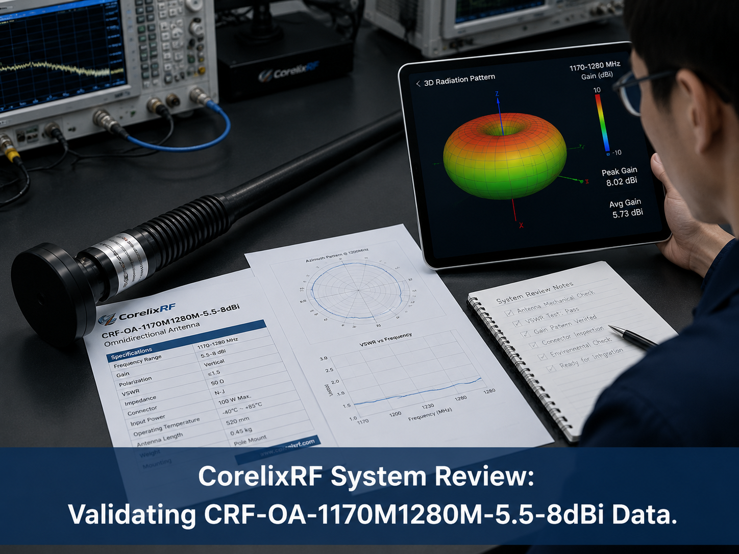
CRF-OA-1170M1280M-5.5-8dBi is a CorelixRF antenna specified from 1170-1280 MHz, with 5.5-8 dBi gain, vertical polarization, datasheet VSWR with representative uploaded test data VSWR, 50 ohm impedance, 50-150 W maximum input power, and N-J connector. This article is based on the antenna specification sheet stored on this computer, and the model name, frequency range, gain, connector, dimensions, mounting, and power handling are kept aligned with that source document.
For engineers selecting an RF antenna, the useful question is not only whether the frequency range appears to match. The antenna also has to fit the coverage geometry, polarization plan, amplifier output power, cable path, mounting structure, and environmental conditions of the system. CorelixRF antenna selection should therefore be reviewed as part of the complete RF chain.
What this antenna is designed to cover
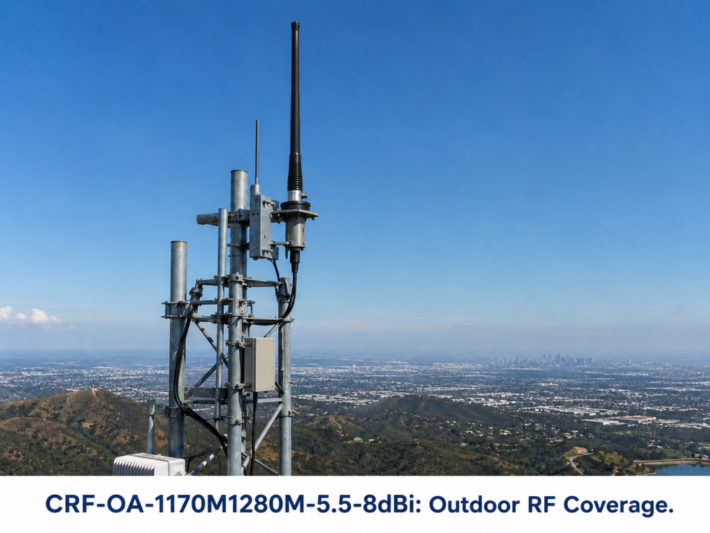
The CRF-OA-1170M1280M-5.5-8dBi covers 1170-1280 MHz. This makes it relevant for outdoor RF coverage, communication systems, fixed installation, and RF system integration. The specification lists 5.5-8 dBi gain and vertical polarization. Those values are central to link budget and field coverage planning because antenna gain changes how much RF energy is directed into the useful coverage area.
Antenna frequency range should be checked against the exact operating channels used in the project. If the RF source, amplifier, filter, or cable assembly covers a wider band than the antenna, the operating procedure should prevent transmission outside the approved antenna range. This is especially important in amplifier-driven systems where a mismatch can trigger reverse power alarms or stress the RF output chain.
Gain, beamwidth, and coverage planning
The source document lists half-power beamwidth and measured horizontal/vertical pattern data at representative frequencies around 1150 MHz and 1250 MHz. Beamwidth helps engineers decide whether the antenna is suitable for broad coverage, sector coverage, point-to-area testing, or controlled RF test geometry. A higher-gain antenna can improve forward coverage or link budget, but it usually narrows the useful radiation area and makes mounting angle more important.
In field installations, the practical pattern can differ from the datasheet pattern. Nearby metal surfaces, masts, brackets, vehicles, enclosures, other antennas, or building edges can change impedance and radiation behavior. For repeatable results, the final installation should document antenna height, orientation, mounting surface, cable route, and nearby objects.
Power handling and RF amplifier matching
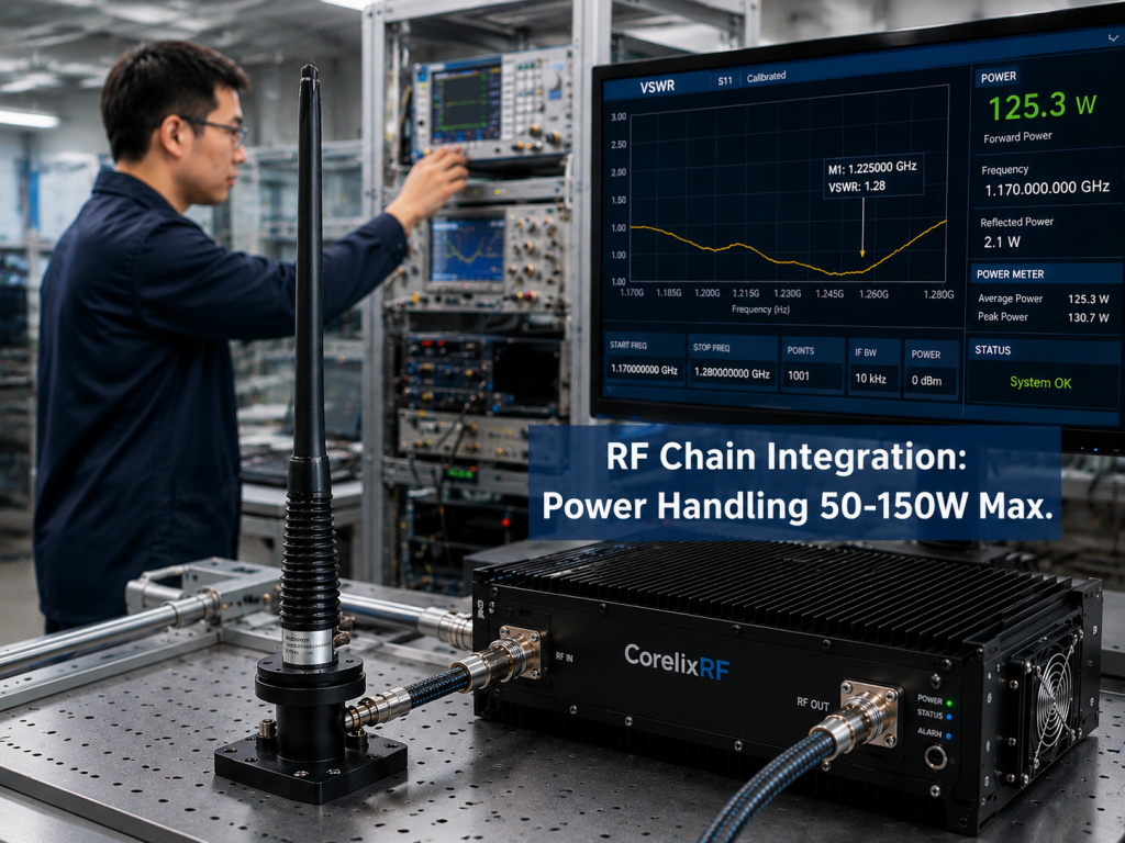
The CRF-OA-1170M1280M-5.5-8dBi specification lists 50-150 W maximum input power. That value should be compared with the output of the RF amplifier, the waveform, duty cycle, cable loss, and expected VSWR condition. A nominal power rating does not mean every amplifier setup is automatically safe. The whole path from amplifier output to antenna connector should be reviewed.
When the antenna is driven by a solid-state RF power amplifier, engineers should verify forward power, reflected power, connector condition, cable rating, and load behavior before long tests. If the amplifier includes VSWR protection, the trip threshold and recovery process should be understood by operators. For high-power operation, antenna selection and amplifier selection should not be handled as separate purchases.
Connector, dimensions, and mounting
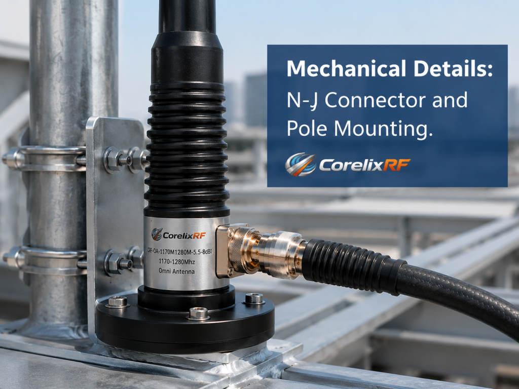
The source specification lists N-J connector and Phi 20-Phi 32 x 600 mm dimensions. Mounting is listed as optional mount styles. These mechanical details affect installation quality as much as RF performance. Connector orientation, strain relief, water protection, bracket rigidity, and service access should be reviewed before the antenna is installed.
For outdoor or semi-permanent systems, mounting hardware should hold alignment over time. For lab systems, the mount should allow repeatable placement. If a cable is added by the integrator, cable type, length, bend radius, insertion loss, and connector sealing should be included in the project documentation.
How to use this antenna in a system review
A practical RFQ should include the exact frequency range, target coverage area, polarization, required gain, maximum input power, connector type, cable requirements, mounting method, environmental exposure, and whether measured VSWR or radiation pattern data is required. If the antenna will be paired with an amplifier, include amplifier output power, duty cycle, waveform type, and protection requirements.
CorelixRF can review antenna options, mounting details, connector needs, radome requirements, and amplifier matching for project-specific systems. The safest purchasing process is to review the antenna as part of a full RF chain that includes the signal source, amplifier, cable assembly, antenna, and test or deployment environment.
Internal links for publishing
RF antennas
RF power amplifiers
Custom RF amplifier and antenna review
Contact CorelixRF
Installation and acceptance checklist
Before final installation, the engineering team should verify the antenna against the real RF path. Check the connector type, cable length, cable loss, mounting height, polarization direction, grounding method, and nearby structures. If the antenna will operate outdoors, confirm radome condition, water protection, bracket rigidity, and cable strain relief. For amplifier-driven systems, first test at reduced power, record forward and reflected power, then increase power only after the antenna path is confirmed. Request the final datasheet, available VSWR data, radiation pattern information, and mechanical drawings so future maintenance teams can reproduce the same installation conditions.
FAQ
What is the frequency range of CRF-OA-1170M1280M-5.5-8dBi?
The source specification lists 1170-1280 MHz operation.
What gain is listed for this antenna?
The specification lists 5.5-8 dBi gain.
What connector does the antenna use?
The source document lists N-J connector.
Can this antenna be used with RF power amplifiers?
Yes, it can be reviewed for amplifier-driven systems, but the amplifier output power, duty cycle, cable loss, connector rating, VSWR, and installation environment must be checked against the antenna specification.