
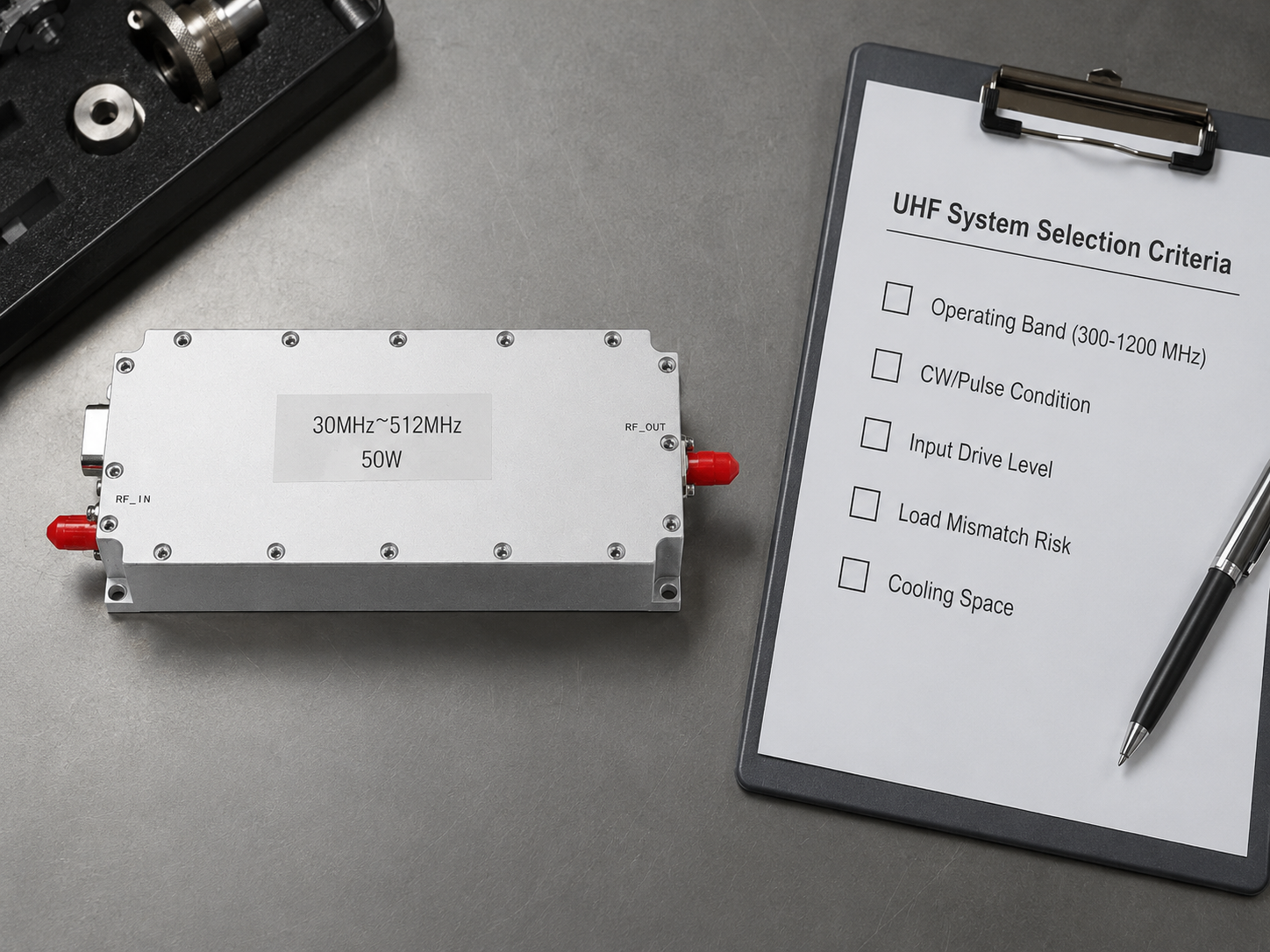
Selecting a UHF RF power amplifier for a broadband system starts with the operating requirement, not the headline wattage. A platform that works well in a narrow laboratory setup may not provide the same output, flatness or thermal margin across 300-1200 MHz. The source level, waveform, cable loss, load VSWR and duty cycle all affect the final choice.
For engineers evaluating this frequency range, CorelixRF provides UHF RF amplifier platforms covering 300-1200 MHz and adjacent bands, with output-power and integration options for RF test, communication and OEM systems.
Start with the actual operating band
Confirm the lowest and highest frequencies the amplifier must support under normal operation. If the system only uses part of the UHF range, define that window clearly. A narrower optimized band may offer better gain flatness, efficiency or cost than a wider platform. If future expansion is likely, include it in the specification before choosing the hardware.
A 300-1200 MHz amplifier is a practical fit for broadband UHF communication, RF module integration and platform validation. Projects that extend below or above this range should also compare 30-512 MHz, 300-1700 MHz and 300-2700 MHz platform families.
Choose output power from the system requirement
Do not select an amplifier only from the nominal power printed on a product page. Work backward from the RF power required at the antenna, device under test or system load. Include cable loss, switches, couplers, filters and any expected mismatch loss. Then add reasonable operating margin so the amplifier does not need to run continuously at its limit.
- Define the required power at the load across the full frequency range.
- Calculate the worst-case loss between the amplifier and the load.
- Check whether the application needs continuous-wave, pulsed or modulated output.
- Allow margin for temperature, frequency response and production variation.
For the 300-1200 MHz platform, standard power classes include 30 W, 50 W, 100 W, 150 W and 200 W. The correct class depends on the complete RF path and operating conditions, not wattage alone.
Check gain and available source drive
The signal generator, transceiver or driver stage must provide enough input power to reach the required output. Compare the available source level with the amplifier gain while allowing for input cable and component loss. CorelixRF’s 300-1200 MHz platforms provide approximately 44-54 dB gain, depending on the selected power configuration.
Gain flatness also matters in broadband systems. A large variation across frequency can change the delivered power and complicate calibration. Ask for measured gain and output-power data across the required band rather than relying on a single center-frequency value.
Define waveform, duty cycle and linearity needs
Continuous-wave operation creates a different thermal load from short pulses. Modulated signals also introduce peak-to-average power requirements that can require additional output back-off. Provide the waveform, pulse width, repetition rate, duty cycle and expected operating time when requesting a configuration.
If signal fidelity is important, state the relevant linearity or distortion target and the power level at which it must be met. This avoids selecting an amplifier that can reach the nominal saturated power but cannot support the required waveform quality.
Confirm supply and cooling conditions
Power amplifiers convert part of the DC input into heat, so the installation must provide adequate cooling. The 300-1200 MHz platform typically uses a 24-32 VDC supply and an external heat sink. Final current, thermal interface and airflow requirements depend on the selected output power and operating profile.
For bench systems, verify that the DC supply can support startup and full-power current without excessive voltage drop. For embedded systems, review heat-sink size, fan airflow, ambient temperature and mounting orientation early in the mechanical design.
Review VSWR, mismatch and protection
The real load may not remain at 50 ohms. Antennas, test fixtures and switching networks can present higher reflected power at some frequencies. Define the expected load VSWR and whether operation may include open, short or rapidly changing loads. Discuss protection behavior, monitoring and recovery with the supplier before finalizing the system.
Plan the mechanical and control interface
Connector type, enclosure format and control method can determine whether an amplifier integrates cleanly into the final product. Confirm RF connector orientation, DC connection, enable or mute control, status monitoring and available panel space. Custom frequency windows, power levels, cooling, control, enclosure and OEM integration can be discussed when a standard module does not match the installation.
Use measured data to compare platforms
A useful quotation should be supported by RF and reliability information relevant to the requested configuration. Ask for available data on output power, gain and flatness across frequency, load or VSWR behavior, thermal performance and aging tests. Also confirm which test report or documentation will be supplied with production units.
| Selection item | 300-1200 MHz platform reference | What to confirm |
|---|---|---|
| Frequency range | 300-1200 MHz | Actual operating window and future extension |
| Output power | 30 W, 50 W, 100 W, 150 W or 200 W | Required load power, path loss and margin |
| Gain | Approximately 44-54 dB | Available source drive and flatness |
| Power supply | Typically 24-32 VDC | Voltage stability and current capacity |
| Cooling | External heat sink | Duty cycle, airflow and ambient temperature |
| Integration | Module and custom options | Connector, control, enclosure and monitoring |
RFQ checklist for a faster technical response
Include the following information in the first request so the application team can evaluate the configuration efficiently:
- Minimum and maximum operating frequency
- Required output power at the load
- Available input power and signal source
- Waveform, modulation, pulse details and duty cycle
- Expected load VSWR and operating environment
- DC supply, cooling and size constraints
- Connector, control, monitoring and enclosure requirements
- Prototype quantity, production quantity and schedule
Frequently asked questions
Is 300-1200 MHz suitable for every UHF application?
No. It is suitable when the required operating frequencies fall within that window. Applications below 300 MHz or above 1200 MHz should use a platform designed for the complete band rather than assuming useful out-of-band performance.
Should I choose the highest available power?
Usually not. Oversizing can increase cost, DC consumption and cooling needs. Select enough power to overcome RF path loss and meet the load requirement with practical margin.
Why does duty cycle matter?
Duty cycle affects average heat generation and therefore the cooling requirement. A short-pulse application and continuous-wave operation can require different thermal designs even when peak RF power is similar.
Can the amplifier be customized for an OEM system?
Yes. Frequency window, output power, connector, cooling, control, enclosure and OEM integration options can be evaluated against the project requirements.
Next step
To narrow the choice, compare UHF amplifier platform options and send the completed RFQ requirements through the CorelixRF contact page. Providing the operating band, power at the load, waveform and integration constraints will lead to a more useful technical recommendation.