
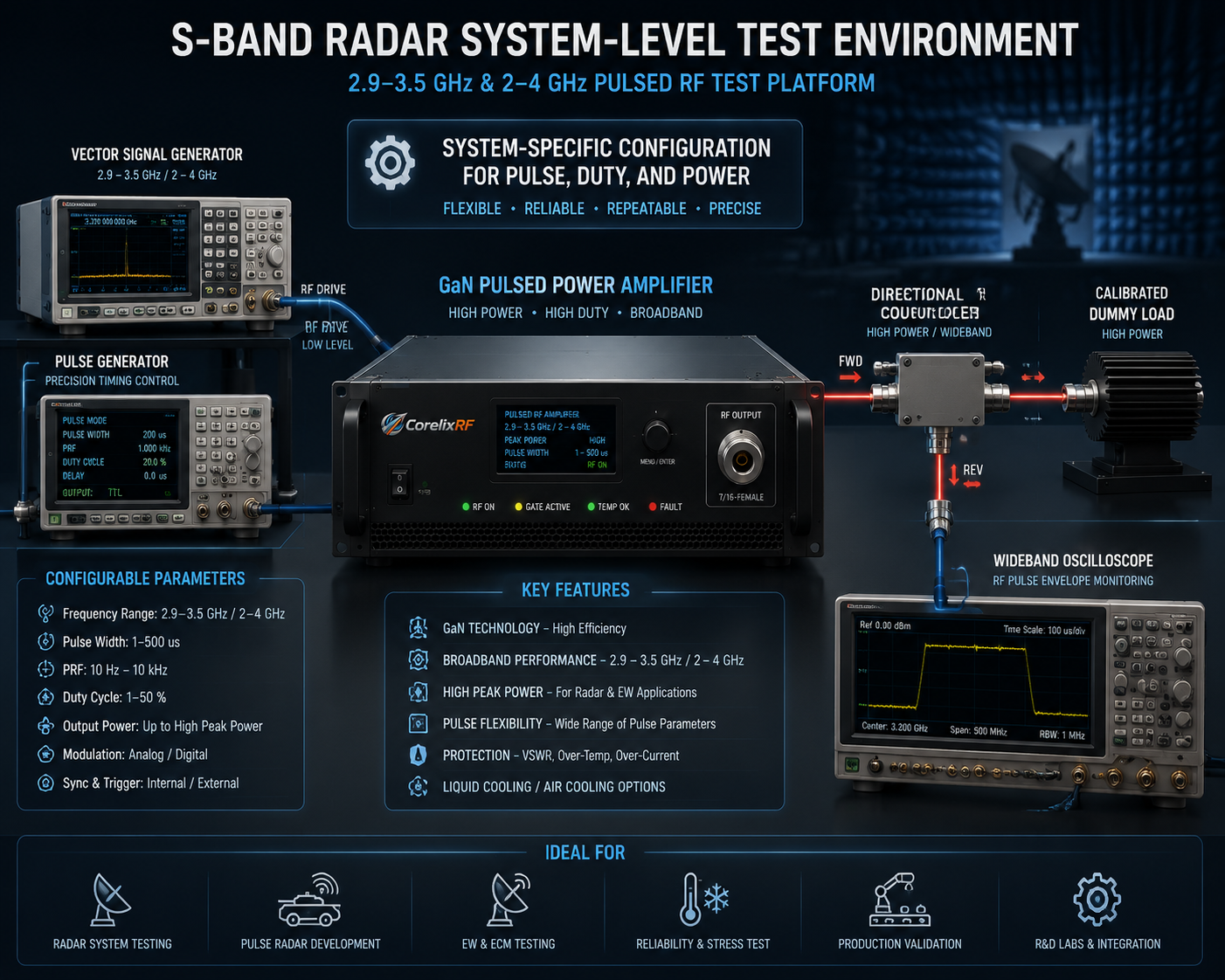
Relevant CorelixRF Products
| Product reference | Frequency range | Peak output power | Gain | Integration notes |
|---|---|---|---|---|
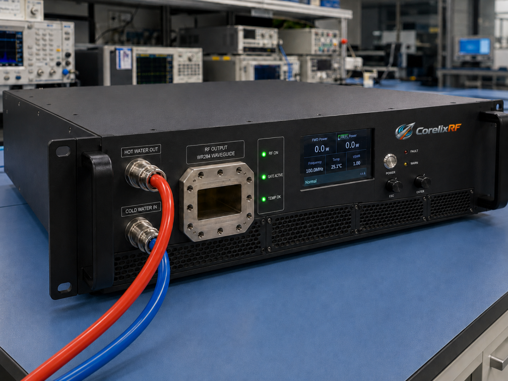
| CRF-PA-2900M3500M-25000W | 2.9-3.5 GHz | 25 kW | 74 dB min. | 200 us typical pulse width, 20% duty, water-cooled cabinet, WR284 output |
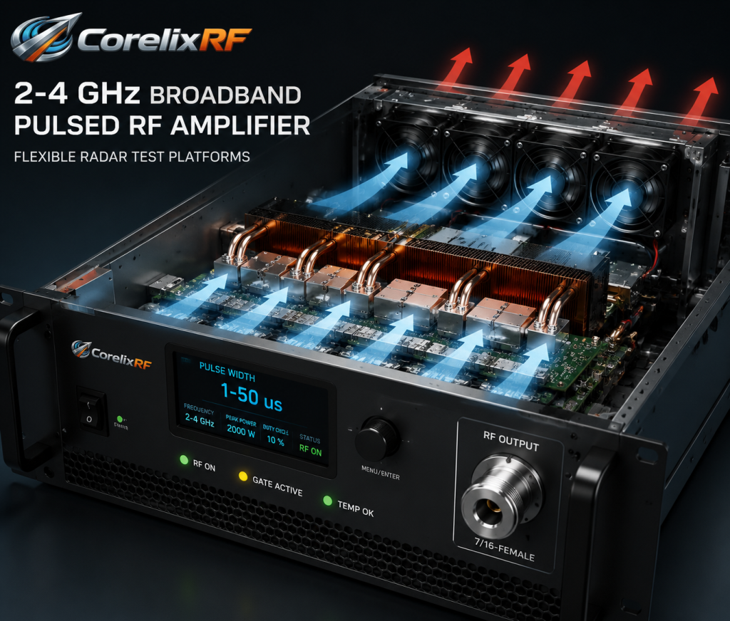
| CRF-PA-2000M4000M-5000W | 2-4 GHz | 5000 W | 60 dB min. | 1-50 us pulse width, 5% duty, forced-air cabinet, 7/16 output |
Pulsed Amplifiers Are Specified by Time as Much as Power
A pulsed RF amplifier for S-band radar test cannot be selected from peak power alone. Pulse width, duty cycle, repetition behavior, blanking, trigger interface, cooling, gain recovery, and protection behavior all affect whether the amplifier fits the test platform. A 25 kW number is meaningful only when the pulse definition and operating envelope are understood.
CorelixRF source specifications include the CRF-PA-2900M3500M-25000W, a GaN pulsed SSPA covering 2900 MHz to 3500 MHz with 25 kW rated peak output power, 200 us typical pulse width, 20% duty cycle, 74 dB minimum gain, 20 dB gain control, N-Female input, WR284 output, RS485/LAN control, AC 380 V +/-10% at 50/60 Hz, and water cooling. The source data also lists the CRF-PA-2000M4000M-5000W, a 2-4 GHz pulsed amplifier with 5000 W pulsed output power, 1-50 us pulse width, 5% duty cycle, 60 dB minimum gain, N-Female input, 7/16-Female output, RS485/LAN control, SMA-F pulse interface, and forced-air cooling.
Define Pulse Requirements Before Frequency Requirements
Frequency range is important, but pulsed systems often fail because the time-domain requirements were not clear. Engineers should document pulse width, duty cycle, pulse repetition frequency, rise/fall expectations if applicable, burst length, blanking behavior, and whether the amplifier will be driven by an internal or external pulse control chain.
For an S-band pulsed RF amplifier, a 2.9-3.5 GHz platform may match a narrower radar-band test need, while a 2-4 GHz platform may support broader experiments with lower peak output. The right choice depends on the actual test mission. If the project needs 25 kW peak power at 2.9-3.5 GHz with 200 us typical pulses and 20% duty, the 25 kW platform is the closer reference. If it needs wider 2-4 GHz coverage with shorter 1-50 us pulses and 5% duty, the 5000 W platform may be the more relevant starting point.
Peak Power, Average Power, and Cooling
Peak power gets attention, but average power drives much of the thermal design. Duty cycle converts high peak power into heat that must be removed by the cooling system. The 25 kW reference platform is listed as water cooled, while the 2-4 GHz 5000 W platform is listed as forced-air cooled. That difference is not cosmetic; it changes the facility plan, service model, installation footprint, and operating procedures.
A GaN pulsed amplifier should therefore be reviewed with both RF and facilities teams. The RF team defines pulses and output path. The facilities team confirms power, cooling, cabinet placement, service clearance, and emergency procedures. Procurement should capture both viewpoints before final configuration.
Output Interface and Load Protection
The 25 kW S-band platform lists a WR284 output. The 2-4 GHz 5000 W platform lists a 7/16-Female output. Each output type implies a different downstream path and accessory set. Waveguide routing, couplers, loads, adapters, and antennas must be rated for the pulse power and duty profile. A component that survives a low-duty bench test may not be suitable for a longer automated run.
Protection features help reduce risk. The source data identifies temperature/current monitoring, optional forward/reverse power monitoring, optional LAN remote monitoring, over-temperature protection, over-drive protection, and VSWR-related alarm functions. However, protection should be supported by good operating procedures: RF drive limits, verified load state, correct pulse settings, and alarm logging.
Controls for Automated Pulse Test Platforms
The control interface matters in pulse testing because timing errors and sequence errors can be expensive. RS485/LAN control can support amplifier status checks, fault reading, and integration with test software. The 2-4 GHz 5000 W source data also lists SMA-F pulse control, which should be reviewed in relation to the signal source, pulse generator, and system controller.
Engineers should ask for the final control protocol during project review. They should also define how the test software handles amplifier warmup, enable, RF drive, pulse trigger, alarm states, and shutdown. This is especially important for unattended or long-duration test campaigns.
Practical Selection Summary
Choose a narrower high-peak pulsed platform when the frequency plan, pulse width, duty cycle, and output interface match the mission. Choose a broader pulsed platform when frequency flexibility matters more than maximum peak output. In both cases, keep claims grounded in the final source data and project-specific acceptance test.
For related broadband needs, review the main RF power amplifier category and adjacent 2-6 GHz amplifier options. For project-specific pulse width, duty cycle, cooling, control, or output interface requirements, start with a custom RF amplifier review rather than forcing a standard line item into a nonstandard test case.
FAQ
What is the focus keyword for this article?
The focus keyword is pulsed RF amplifier for S-band radar test.
What peak power is listed for the 2.9-3.5 GHz platform?
The source specification lists 25 kW rated peak output power for CRF-PA-2900M3500M-25000W.
What pulse parameters are listed for the 25 kW platform?
The source data lists 200 us typical pulse width and 20% duty cycle.
Why does average power matter?
Average power determines much of the thermal load, cooling requirement, and operating envelope, even when the headline specification is peak power.
What should be included in a pulsed amplifier RFQ?
Include frequency range, peak power, pulse width, duty cycle, PRF or timing requirements, output interface, cooling preference, control interface, and expected test duration.