
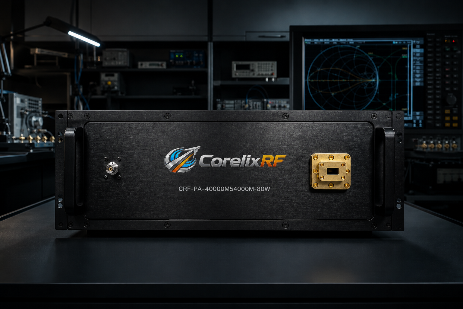
Relevant CorelixRF Products
| Product reference | Frequency range | Output power | Gain | Integration notes |
|---|---|---|---|---|
| CRF-PA-40000M54000M-80W | 40-54 GHz | 80 W | 50 dB min. | 1.85 mm input, WR19 output, 19-inch 5U, forced-air cooling |
Why 40-54 GHz Changes the Amplifier Review
A 40-54 GHz mmWave power amplifier is selected differently from a lower-frequency broadband RF power amplifier. At this band, connector strategy, waveguide routing, gain flatness, thermal margin, protection behavior, and control interfaces have a direct effect on whether the finished test system is repeatable. The amplifier is not simply a gain block placed near the end of the chain. It is a high-power RF subsystem that must be reviewed with the source, switching network, couplers, loads, interlocks, and mechanical airflow plan.
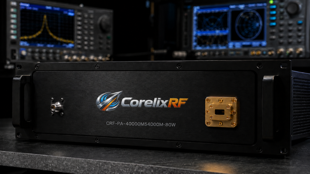
CorelixRF source specifications list the CRF-PA-40000M54000M-80W as a GaN solid-state power amplifier covering 40 GHz to 54 GHz with 80 W rated output power and 50 dB minimum small-signal gain. The platform uses a 1.85 mm female RF input and WR19 waveguide RF output, supports RS485 and LAN control, operates from AC 220 V +/-10% at 50/60 Hz, and is described in a 19-inch 5U forced-air configuration. These details matter because mmWave test platforms usually fail at the interfaces before they fail in the headline frequency line.
Start With Frequency Coverage and Test Margin
The first review item is coverage. A 40-54 GHz amplifier spans a demanding portion of the mmWave range, so the engineer should map the required test points, modulation bandwidth, dwell time, and target field or delivered power before requesting a configuration. If the test plan only uses a narrow part of the band, the system can still benefit from wide coverage when future test cases or frequency-agile sources are expected. If the full 40-54 GHz range is required, gain flatness becomes more important because power correction tables may otherwise become large and difficult to maintain.
The CorelixRF data shows gain flatness of -10 to +10 dB for this 80 W platform. That figure should be reviewed in the context of the complete RF path: source flatness, cable or waveguide loss, coupler coupling factor, switch loss, and load or antenna behavior. In practice, a GaN SSPA in this range should be specified as part of a calibrated system rather than as an isolated catalog line.
Review Power, Gain, and Drive Level Together
Output power and gain must be reviewed together. An 80 W rated output with 50 dB minimum gain can reduce the source drive requirement, but it also makes overdrive protection and drive-level discipline important. The source specification lists a 15 dB gain control range, harmonics at -20 dBc, and spurious performance to -60 dBc. These are useful starting points for a system review, but the final acceptance plan should define measured output power, flatness, gain-control resolution, harmonic filtering needs, and permitted spurious levels under the intended operating mode.
For procurement teams, the practical question is not only “Can the amplifier reach 80 W?” The better question is: can it reach the required delivered power after the real waveguide path, while staying inside the thermal, duty, and protection limits of the integrated system?
Connector and Waveguide Planning
The CRF-PA-40000M54000M-80W uses a 1.85 mm female input and WR19 output. That combination reflects a normal transition from coaxial source instrumentation to a waveguide output path. Engineers should review bend radius, waveguide flange compatibility, adapter count, coupler placement, and load rating before ordering. Each adapter can add uncertainty, and each mismatch can increase reflected power risk.
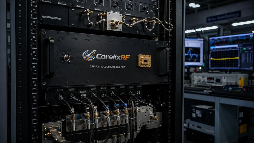
A waveguide RF amplifier also affects mechanical layout. The output path may define the amplifier position more strongly than the rack plan. If the amplifier must connect to an antenna, chamber feedthrough, or high-power load, those mechanical constraints should be supplied early so the final mechanical drawing can be reviewed against the lab layout.
Cooling, Monitoring, and Protection
The source data describes forced-air cooling, real-time temperature monitoring, real-time current monitoring, optional forward/reverse power monitoring, optional input power detection, over-temperature protection, over-drive protection, over-voltage protection, and VSWR protection/alarm functions. These features are important for mmWave systems because expensive downstream components can be damaged by mismatch, incorrect sequencing, or thermal stress.
When specifying a solid state power amplifier, ask how alarms are exposed over RS485 or LAN, whether the controller can log fault states, and how the amplifier should be sequenced with the RF source. In automated test, the control interface is often as important as the RF connector. A test script that can read amplifier state, confirm temperature, and pause after a reflected-power alarm is easier to maintain than a manual-only workflow.
When to Request a Custom Review
A custom review is appropriate when the project includes unusual duty cycle, chamber integration, tight gain flatness, remote operation, nonstandard interlocks, or a specific mechanical envelope. The CorelixRF source sheet states that final mechanical drawing, test data, and control protocol can be supplied for project review where applicable. That language is useful for procurement because it keeps claims tied to final configuration instead of assuming every project uses the same drawing or interface package.
If your project spans lower microwave bands as well, review the broader RF power amplifier portfolio and compare with adjacent 6-18 GHz amplifier requirements. For a multi-band program, one amplifier rarely solves every band with equal efficiency; a banded architecture often gives better power, cooling, and acceptance-test clarity.
FAQ
What is the focus keyword for this article?
The focus keyword is 40-54 GHz mmWave power amplifier.
What output interface is listed for the 40-54 GHz 80 W platform?
The source specification lists a WR19 waveguide output, with a 1.85 mm female RF input.
Is the amplifier liquid cooled?
The referenced 40-54 GHz 80 W source specification describes forced-air cooling in a 19-inch 5U configuration.
Can CorelixRF provide final mechanical drawings?
The source data states that final mechanical drawing, test data, and control protocol can be supplied for project review where applicable.
Should this amplifier be reviewed as a standalone component?
It should be reviewed as part of the complete RF path, including source drive, waveguide routing, couplers, load or antenna, cooling, and control interface.