
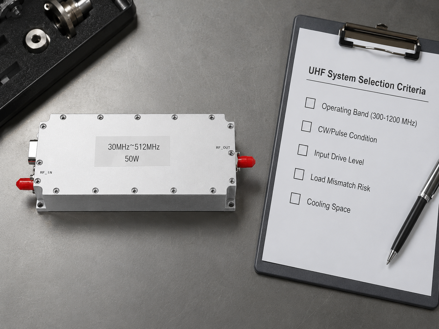
Selecting an EMC RF amplifier for immunity testing is rarely about choosing the highest wattage box in the budget. In practice, most lab teams need a more disciplined match between frequency range, test method, duty mode, protection strategy, and the way the amplifier will be integrated into the bench. Overbuying adds cost and size, but under-defining the requirement usually creates retest cycles, unstable results, or thermal problems during longer runs.
CorelixRF positions this topic from the hardware side rather than from the certification-service side. Its EMC amplifier platform and EMC & laboratory RF systems pages both make the same point: the useful starting inputs are frequency range, output power, CW or pulse operation, cooling, protection logic, control interface, and rack integration needs. That is a more realistic workflow than trying to pick an amplifier from power alone.
Start with the Actual Test Band, Not a Generic “Broadband” Label
One of the most common mistakes in EMC planning is using “broadband RF power amplifier” as if it automatically answers the requirement. It does not. The right first question is which frequency span must be covered by the immunity setup, and whether the entire band truly needs one amplifier or whether the chain should be split into practical blocks.
If your test environment sits in lower RF ranges, a 30-512 MHz RF power amplifier or a 300-1700 MHz platform may align better than a wider but less targeted option. If the lab also works into upper microwave bands, the review path often moves toward 2-6 GHz amplifiers or a high-frequency capability review.
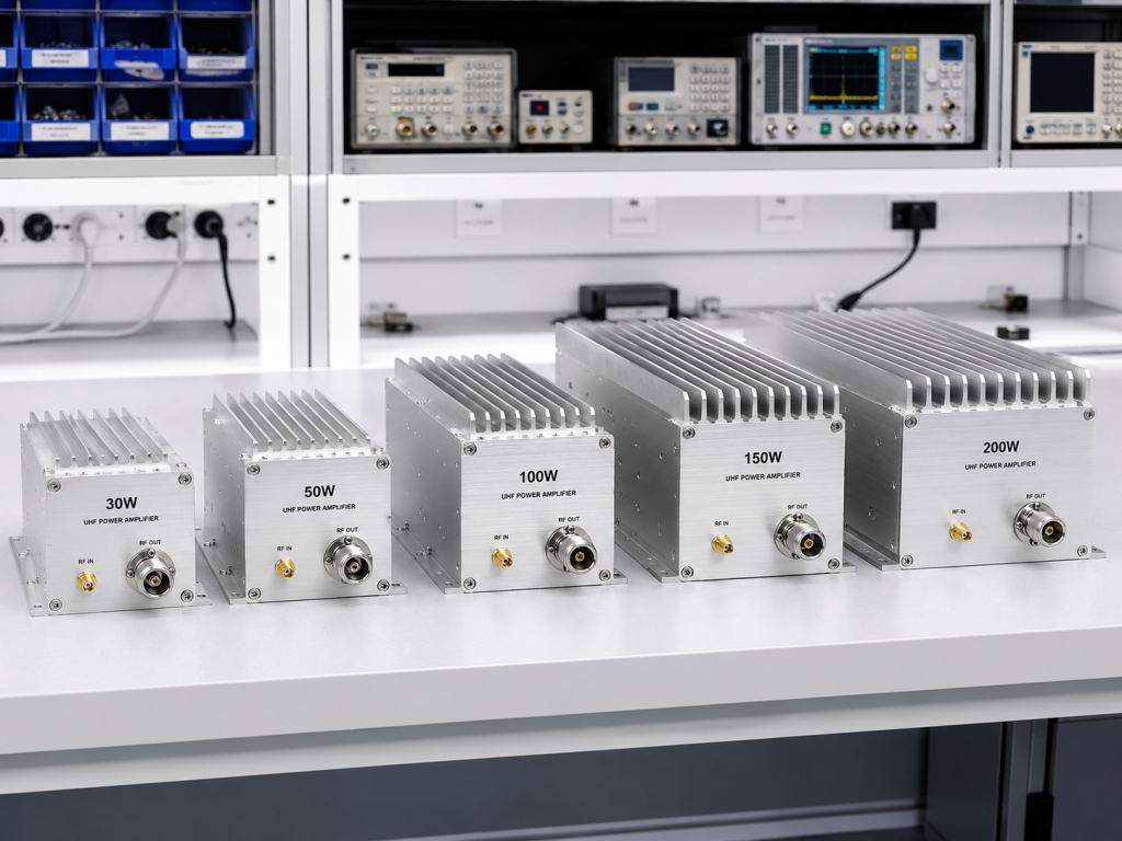
The goal is not a perfect one-box solution. The goal is a band-matched amplifier path that is easier to cool, validate, and repeat.
Define Output Power in System Context
For immunity testing, output power should not be treated as a standalone number. Engineers need to consider couplers, cable loss, antenna gain, field targets, and mismatch conditions. That is why a bench that looks manageable on paper can still become unstable once the full path is assembled.
CorelixRF’s public pages consistently frame amplifier projects as part of a larger chain that may include source, coupler, antenna or load, and analyzer. The RF testing and validation page is useful here because it emphasizes chain-level review rather than component-only selection.
When you define power, clarify:
- Required output at the amplifier
- Estimated loss through the path
- Expected load behavior and mismatch risk
- Whether the requirement is for bench validation or longer compliance-oriented operation
Which Operating Mode Matters Most: CW, Sweep, or Pulse?
The amplifier that works for one EMC lab profile may not be the best fit for another. Some setups prioritize continuous-wave stability, while others need sweep behavior, dwell control, or pulsed operation. Those choices affect thermal planning, device stress, and protection logic.
CorelixRF’s EMC page explicitly notes support for CW or pulse operation, as well as cooling and protection review. That matters because immunity-related environments can expose amplifiers to long on-time windows, operator changes, and variable load conditions. If the intended duty mode is unclear, the procurement risk rises immediately.
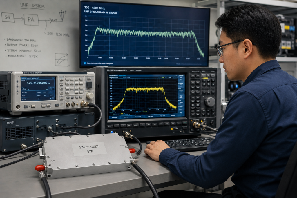
In practical terms, the purchasing checklist should ask for:
- Required operating mode and duty cycle
- Expected test duration at higher output levels
- Acceptable thermal derating, if any
- Whether the setup needs rack-mount or compact bench integration
Protection and Load Review Are Not Optional
In a real laboratory chain, mismatch happens. Cables change, couplers vary, antennas are swapped, and different benches are reconfigured under schedule pressure. That is why the amplifier protection strategy matters almost as much as raw RF performance.
For an RF immunity testing amplifier, engineers should review VSWR tolerance, over-temperature logic, over-voltage protection, airflow assumptions, and how the unit behaves during abnormal load conditions. Public CorelixRF material repeatedly references protection, measured data, and factory-side engineering review before quotation. That is a stronger buying signal than vague claims about “rugged design” without a documented review path.
If your team is comparing vendors, ask which protection mechanisms are standard and which are project-dependent. Also confirm whether measured records are available before shipment for the specific configuration under review.
Think About Integration Early
An EMC amplifier is often treated as a late purchase, but integration details drive many avoidable delays. The questions should be settled before RFQ whenever possible:
- What RF connector format does the bench require?
- What DC input and facility power are available?
- Does the lab need local control only, or remote interface support?
- Will the unit sit in a rack, on a cart, or on an open bench?
- Is airflow predictable, or will the amplifier run inside a tighter cabinet?
The CorelixRF contact page is explicit about the information that speeds review: frequency, output power, duty mode, cooling, connector preference, control interface, and application stage. That is a useful template for internal requirement capture too.
Validation Matters More Than Marketing Language
The safest shortlist is usually built around vendors that can discuss unit-level RF validation, not just nominal datasheet numbers. CorelixRF’s factory pages repeatedly reference measured data, engineering review, and test documentation. For technical buyers, that is the right conversation because it supports repeatability and internal sign-off.
When reviewing an EMC amplifier proposal, ask whether the supplier can support:
- Frequency and power confirmation for the actual requested band
- Test data before shipment
- Documentation suitable for internal engineering or purchasing review
- A clear escalation path if the project shifts from a standard platform to a modified configuration
This is particularly important when the same lab may later expand into RF signal transmission projects or other mixed bench applications.
A Practical Selection Framework
For most labs, the cleanest path is:
- Define the real test band and whether one amplifier or multiple band blocks make more sense.
- Estimate required delivered power at the load or antenna path, not just amplifier output.
- Confirm CW or pulse behavior, thermal duty, and expected runtime.
- Review connectors, DC input, control interface, and rack or bench format.
- Ask for measured data and protection details before purchasing.
That process reduces both overspecification and avoidable redesign.
FAQ
What is the most important parameter in an EMC RF amplifier for immunity testing?
The most important parameter is not a single number. Frequency range, output power at the system level, operating mode, cooling, and protection must be matched together.
Should one broadband RF amplifier cover every EMC test band?
Not always. Many projects are better served by band-matched amplifier blocks that are easier to optimize and validate than one very broad compromise platform.
Why does cooling matter so much in immunity testing?
Immunity testing can involve long dwell times or repeated sequences. Thermal margin directly affects stability, protection behavior, and repeatability.
What information should be prepared before requesting a quotation?
Prepare frequency range, output power target, operating mode, load or antenna condition, connector type, control needs, cooling assumptions, and installation format.