
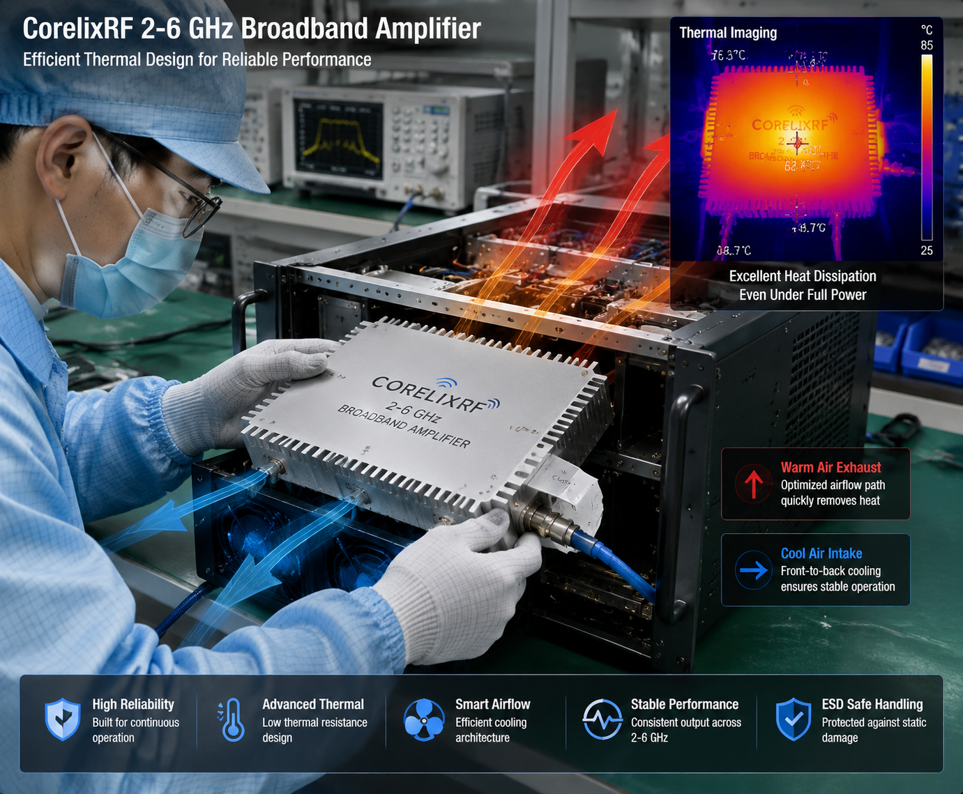
Search demand around 2-6 GHz RF power amplifier for SDR test bench is highly practical because many development teams now work across Wi-Fi-adjacent bands, C-band ranges, and custom microwave paths without wanting to redesign the whole bench for every project. The problem is that “SDR compatible” does not automatically mean the amplifier is well matched to the test workflow.
CorelixRF’s 2-6 GHz RF power amplifier page presents the band as a factory-direct broadband module class for RF testing, communications, and system integration. That is the right framing. For engineers, the key is to translate that broad statement into a selection process that considers source output, gain planning, duty cycle, control, and thermal limits.
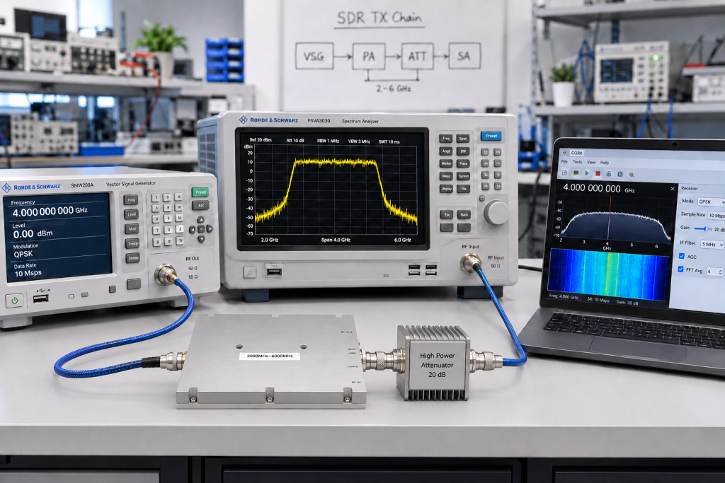
Why 2-6 GHz Is a Popular SDR Expansion Band
Many SDR-based development environments begin with flexible signal generation and then hit a practical limit: source-level output is not enough for realistic chain testing, front-end stress, subsystem evaluation, or antenna-path work. That is where a dedicated 2-6 GHz broadband RF amplifier becomes useful.
CorelixRF’s RF signal transmission application page describes the signal path as source or SDR, CW amplifier, then antenna or load. That sequence is important because it reminds buyers that the amplifier should not be chosen in isolation. It must match the SDR output level, the desired end power, and the actual downstream load path.
Match Frequency Coverage to the Real Test Plan
The first question is whether the entire 2-6 GHz span is genuinely needed, or whether the project operates in narrower windows such as 2.4 GHz, 5.2 GHz, or 5.8 GHz. A full-band amplifier gives flexibility, but a narrower implementation may provide a better balance of output power, efficiency, and thermal control depending on the project.
CorelixRF’s public material states standard broadband modules covering 2,000-6,000 MHz, with engineering documentation, mechanical drawings, and performance curves available for review. That is helpful for bench planners because it suggests the selection process can move from broad platform class to exact project match.
In internal design review, clarify:
- Minimum and maximum operating frequencies
- Whether output must be flat across the band or optimized around sub-bands
- Which test points are critical for pass/fail decisions
Output Power Is Only Part of the Story
A common purchase error is picking power based on headline wattage without checking the upstream source and downstream loss budget. SDR outputs are typically modest, so gain planning matters. If the chain includes attenuators, couplers, switches, combiners, or longer cables, the effective delivered power may differ sharply from the amplifier nameplate.
CorelixRF’s site emphasizes application-side matching, not just module-only promotion. That is the better buying model. Ask how the amplifier fits with the planned signal source, cable path, and load condition. In some cases, the right solution is a standard platform. In others, the project may need custom RF development to address connector layout, enclosure, or interface requirements.
CW Stability and Thermal Planning Matter for Bench Work
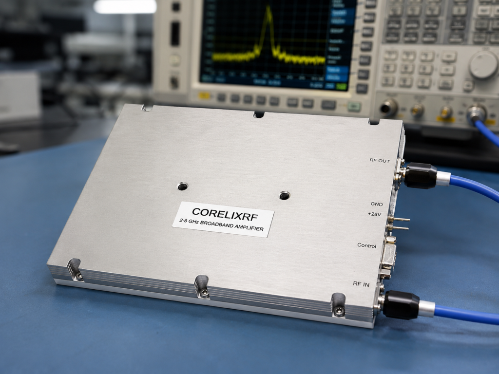
An SDR test bench often runs longer than teams first expect. Sweeps, repeated captures, validation loops, and debugging sessions can keep the amplifier active for extended periods. That makes cooling and duty assumptions critical.
CorelixRF’s 2-6 GHz page positions the band for RF testing and system integration, while its broader factory pages emphasize engineering review before quotation. That is useful because long-run bench stability depends on more than broadband coverage. It depends on airflow, mounting, ambient conditions, and whether the amplifier is a compact module or a larger chassis-based implementation.
If the bench may scale from evaluation to heavier use, review:
- Air cooling assumptions
- Mounting orientation
- Continuous operation expectations
- DC input and facility power limits
Interfaces and Control Should Be Planned Up Front
Many SDR labs start with manual bench work and then add automation later. If that shift is likely, interface planning should happen before procurement. CorelixRF’s high-frequency and systems pages show that some higher-band projects can involve control interfaces such as RS485 or LAN, while the contact workflow asks buyers to define control needs early.
That matters for repeatable bench operation. If the team expects remote enable, monitoring, or easier fault handling, the amplifier specification should reflect it from day one. Waiting until later often forces avoidable rework.
Use Internal Links to Support the Buying Journey
For content strategy, this topic connects naturally to several existing CorelixRF pages. Buyers evaluating a 2-6 GHz SDR bench may also need RF testing and validation support, RF signal transmission solutions, 6-18 GHz broadband RF amplifiers if the test program expands upward, and the CorelixRF contact page for frequency, power, connector, and cooling review.
Those paths are useful because they move the article from informational intent toward project-fit evaluation without making unrealistic claims.
A Practical Checklist for SDR Teams
Before sending an RFQ, an SDR bench team should prepare:
- Required frequency window inside the 2-6 GHz range
- Target output power at the device under test or load
- Source level from the SDR or signal generator
- Continuous or burst operating pattern
- Connector preference and cable architecture
- Cooling and installation format
- Whether future automation or monitoring is expected
This reduces the usual back-and-forth and improves the chance of getting a useful amplifier recommendation instead of a generic product list.
FAQ
Why is a 2-6 GHz amplifier popular in SDR labs?
It covers a useful upper RF range for broadband bench work, front-end evaluation, and multi-band project development while remaining compatible with many SDR-driven workflows.
Does an SDR source directly determine which amplifier to choose?
No. The source level matters, but the full chain also includes gain target, downstream losses, load condition, operating mode, and cooling constraints.
When should a team consider custom RF development instead of a standard amplifier?
Consider a custom path when the project needs non-standard interfaces, enclosure changes, connector layouts, control requirements, or unusual sub-band optimization.
What should be verified before purchase?
Verify actual operating band, output target, duty profile, connector and DC requirements, cooling assumptions, and whether measured data can be provided.