
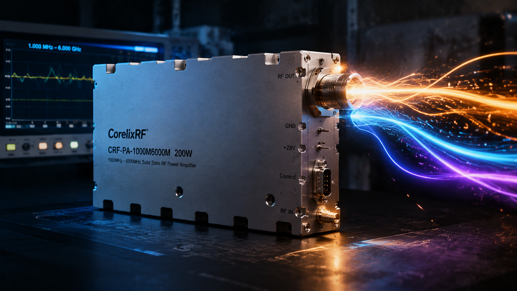
A 1-6 GHz 200 W RF power amplifier sits in a useful but demanding part of the engineering test chain. It has to cover L-band, S-band, C-band, and many intermediate test cases without forcing the lab to swap amplifiers every time the frequency plan changes. For system engineers, the real question is not only whether the amplifier reaches 200 W. It is whether the amplifier can deliver that power across a broad operating window, accept realistic drive levels, provide enough gain margin, and fit the control and cooling model of the final rack or bench.
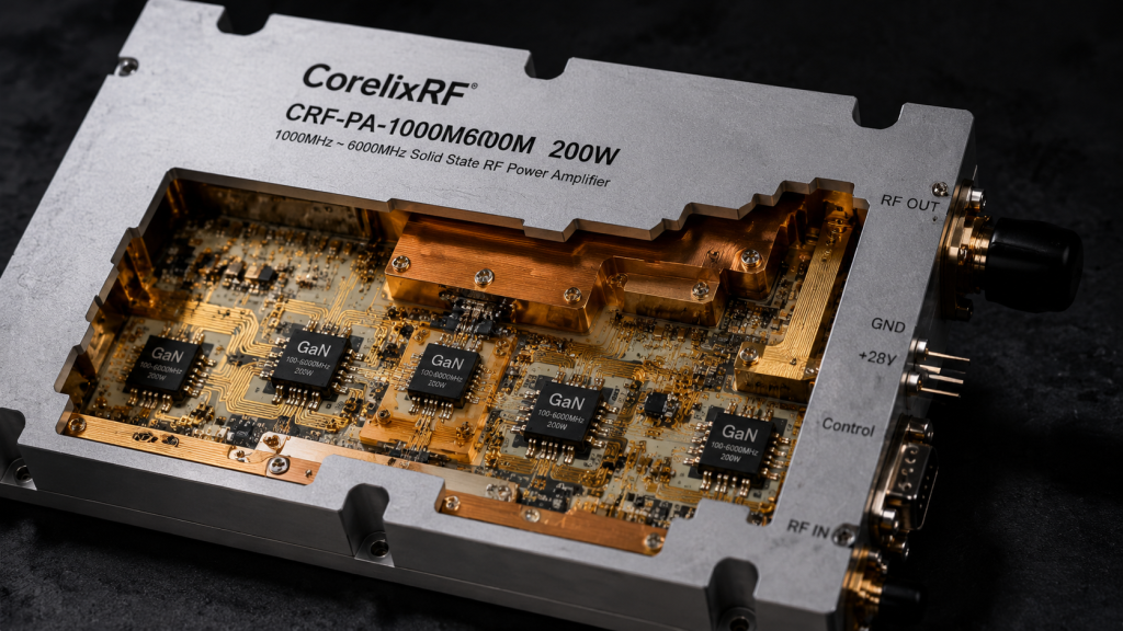
CorelixRF’s CRF-PA-1000M6000M-200W is specified as a solid-state GaN RF power amplifier covering 1 GHz to 6 GHz with 200 W rated output power. The datasheet lists 53 dB minimum small-signal gain, +/-5 dB gain flatness, 0 dBm maximum input power, SMA-F input, N-F output, RS485 control, 28 V DC supply, and a 400 x 300 x 80 mm forced-air mechanical format. Those details make it relevant for engineers comparing a high-power RF power amplifier for broadband communications, RF interference testing, aerospace control benches, and general test and measurement work.
Why 1-6 GHz Coverage Matters
The 1-6 GHz range is attractive because it spans multiple application bands while remaining low enough that cable loss, connector selection, and load handling are still practical for many labs. A broadband RF power amplifier in this range can support swept-frequency tests, multi-band equipment checks, transceiver stress testing, and RF front-end validation without rebuilding the entire setup.
A narrowband amplifier may be more efficient at one fixed channel, but broadband coverage gives the test team room to evaluate system behavior across transitions. That matters when an RF chain includes filters, switches, couplers, limiters, antennas, or software-defined radios whose response changes with frequency. A 1-6 GHz amplifier can become a shared lab asset rather than a single-purpose device.
Reading the 200 W Output Rating Correctly
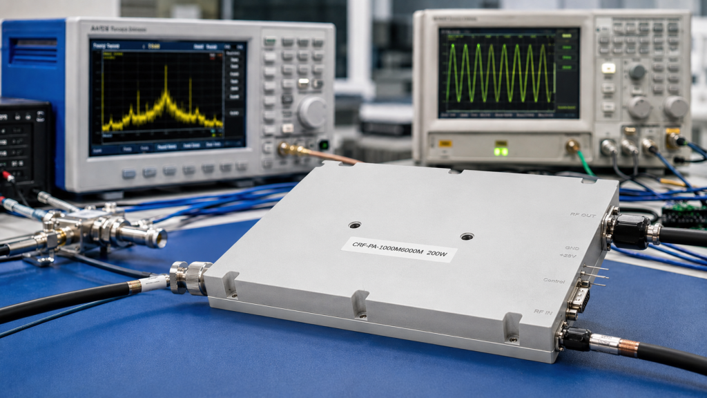
The 200 W rating should be treated as an engineering parameter, not a marketing shortcut. Before placing a purchase order, the team should confirm the required output power at the device under test, then subtract losses from cables, directional couplers, attenuators, switches, and any protection hardware between the amplifier and the load. At 1-6 GHz, even moderate cable runs can create enough loss to change the amplifier size needed for a repeatable test.
The CRF-PA-1000M6000M-200W also lists 53 dB minimum gain. That is important because it helps define the signal generator or driver level. With a high-gain amplifier, the source does not need to deliver large RF power, but the operator must respect the 0 dBm maximum input power and build in attenuation, interlocks, and operating procedures that prevent accidental overdrive.
Gain Flatness and Test Repeatability
Gain flatness is often where broadband amplifier projects become more complex. The listed +/-5 dB flatness means the system designer should expect output variation across the band and plan the calibration process accordingly. In a production or qualification setup, that normally means building a frequency-by-frequency correction table, measuring forward power with a calibrated coupler, and controlling the input level rather than assuming one generator setting will produce the same output everywhere.
This is especially relevant in RF immunity, interference, and multi-band communication test setups where the acceptance criterion is tied to delivered field strength or delivered RF power. A 200 W amplifier may have enough headroom, but the test plan still needs power monitoring and limits.
Interface, Cooling, and Rack Integration
The mechanical and electrical interfaces are practical details that should be reviewed early. This model uses SMA-F at the input and N-F at the output. That combination makes sense for many broadband benches, but the output connector, cable assembly, load, and attenuator must all be rated for the expected power and frequency. The amplifier uses a 28 V DC supply and forced-air cooling in a 400 x 300 x 80 mm form factor, so the rack design must provide adequate airflow and service access.
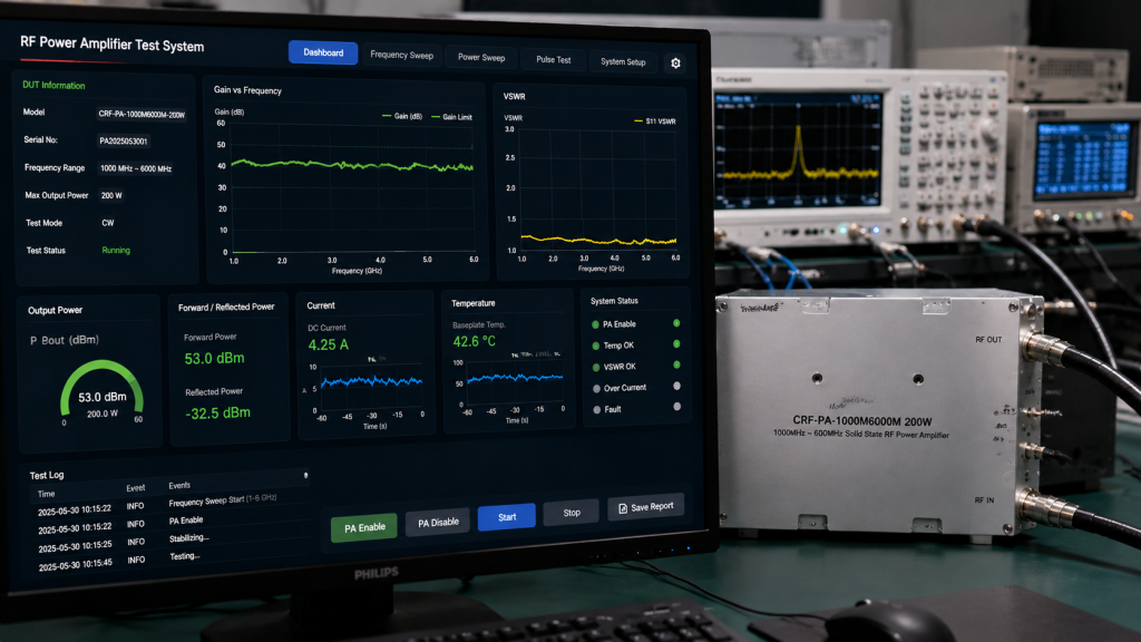
For automated systems, RS485 control gives the integrator a route for remote operation and status handling. When engineers discuss a custom RF amplifier requirement with CorelixRF, the control protocol, alarm behavior, and monitoring signals should be included in the review, not left as final wiring details.
Protection Features to Include in the Test Plan
The datasheet references temperature and current monitoring, optional forward/reverse power monitoring, alarm functions, over-temperature protection, over-drive protection, over-voltage protection, and VSWR protection. These features are valuable, but they do not remove the need for correct external protection. A mismatched antenna, damaged cable, open output, or wrong attenuator can still create risk in a high-power RF chain.
A good system plan includes rated terminations, directional couplers, interlocked enclosures where needed, verified airflow, and procedures for ramping power. Protection functions should be tested during commissioning so operators know how the amplifier reports faults and how it recovers.
Where This Amplifier Fits Best
A 1-6 GHz 200 W GaN SSPA is a strong fit when the project needs broadband RF coverage with meaningful CW power, but the team still wants a solid-state platform with monitoring and controllability. Typical uses include broadband subsystem testing, RF interference system-level work, communication equipment evaluation, and aerospace control test setups. It is also a useful reference point when comparing lower-power SDR RF amplifier chains against higher-power bench requirements.
RFQ Checklist for a 1-6 GHz 200 W Amplifier
Before asking for a quotation, define the continuous frequency range, target output power at the load, acceptable gain flatness, signal source level, duty cycle, required control interface, available DC power, cooling constraints, connector preference, and expected load mismatch conditions. If the amplifier will be installed in a rack, include airflow direction, cable bend limits, and service access.
FAQ
Is a 1-6 GHz amplifier better than several narrowband amplifiers?
It depends on the test plan. A broadband amplifier is better when the same bench must support multiple bands, swept tests, or changing programs. Narrowband amplifiers can be attractive for fixed-channel efficiency or compact integration.
Why does the input power limit matter?
The listed 0 dBm maximum input power helps prevent overdrive. Even if the amplifier has protection functions, the source chain should include attenuation and operating limits.
Can this amplifier support automated testing?
The RS485 control interface and monitoring functions make it suitable for automated benches, provided the command protocol and fault handling are reviewed during integration.
What should be verified before final selection?
Confirm output power across the required frequencies, load conditions, cooling, connector ratings, control needs, and any project-specific mechanical constraints.