
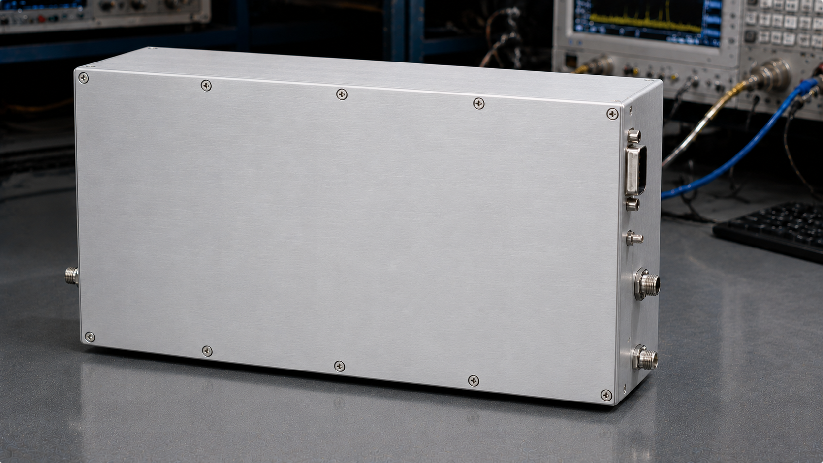
A 10.7-12.7 GHz 100 W RF power amplifier is usually purchased for a specific engineering reason: the test team needs high-power Ku-band coverage without moving to a much wider, more expensive microwave amplifier than the job requires. This frequency range is relevant to satellite communication payload work, receiver stress testing, RF link verification, and system-level interference simulation. At these frequencies, the amplifier is only one part of the decision. Waveguide output, cooling, gain control, power supply design, and measurement calibration all influence whether the finished bench is stable and repeatable.
CorelixRF’s CRF-PA-10700M12700M-100W is specified for 10.7 GHz to 12.7 GHz with 100 W typical rated output power. The datasheet lists 50 dB minimum gain, +/-2.5 dB typical gain flatness, 20 dB gain control in 1 dB steps, 0 dBm maximum input power, SMA-F input, WR75 output, RS485 control, 28 V DC supply at 30 A, and system-level forced-air cooling. Those specifications make it a useful candidate for engineers comparing a Ku-band microwave power amplifier for laboratory and integrated RF systems.
Why This Band Needs Focused Selection
Ku-band test systems expose weak assumptions in the RF chain. Cable loss is higher than at lower microwave frequencies, connector repeatability matters more, and waveguide transitions can become part of the calibration uncertainty. A 100 W amplifier is powerful enough that the system must be designed around safe power handling, but precise enough that the engineer cannot ignore gain flatness or control resolution.
A focused 10.7-12.7 GHz design can be more practical than using a very wideband amplifier when the application stays inside this band. It allows the buyer to concentrate on output interface, gain control, thermal behavior, and test repeatability for the actual operating window.
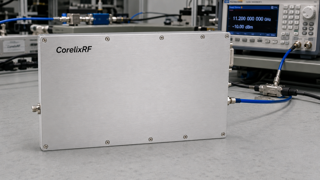
Output Power and Gain Control
The CRF-PA-10700M12700M-100W is listed with 100 W typical output power and 50 dB minimum gain. For most test benches, that gain level means a modest signal generator output can drive the amplifier, but the 0 dBm input limit must be respected. Operators should not rely on software settings alone; fixed attenuation, interlocks, and written startup procedures help prevent accidental overdrive.
The 20 dB gain control range in 1 dB steps is especially valuable for Ku-band work. It allows the integrator to tune delivered power without constantly changing the signal source level. That can simplify automated sweeps, reduce operator error, and make it easier to maintain consistent input conditions for upstream equipment.
WR75 Output and Measurement Planning
The WR75 output interface is a major integration detail. Waveguide output can be appropriate for high-power Ku-band delivery, but the rest of the setup must match it. Directional couplers, loads, adapters, antenna feeds, and test fixtures need compatible frequency coverage and power ratings. If a coaxial transition is required, its insertion loss, return loss, and power limit must be included in the budget.
When comparing this amplifier with other solid state power amplifier options, ask for the measurement reference plane. Output power at the amplifier flange is not the same as delivered power after a long waveguide run, switch matrix, or coupler stack. A calibration plan should define where power is measured and how correction factors are applied.
Cooling and Mechanical Review
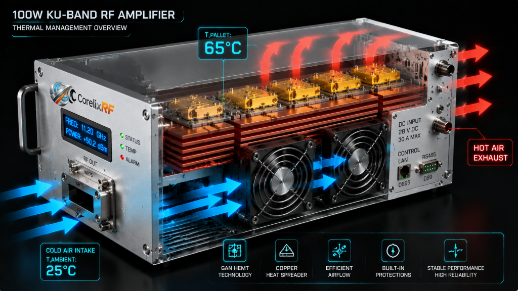
The datasheet marks the final mechanical form factor as project-dependent and notes that system-level forced-air cooling is required. That is a useful warning for integrators. A 100 W Ku-band amplifier does not belong in a closed rack bay without airflow analysis. The final enclosure should allow intake and exhaust clearance, temperature monitoring, service access, and cable routing that does not block airflow.
Because the amplifier uses a 28 V DC supply at up to 30 A, power distribution should be reviewed with the same care as RF cabling. Voltage drop, connector current rating, grounding, and protection devices should be part of the system drawing.
Applications That Fit the 10.7-12.7 GHz Range
This amplifier is most relevant where the project needs controlled Ku-band RF power rather than broad spectrum coverage. Example use cases include satellite payload and ground equipment testing, receiver robustness checks, microwave component evaluation, communication link simulation, and RF interference system-level testing. Teams developing higher-frequency programs can also use it as a practical step between lower microwave amplifiers and broader mmWave amplifier platforms.
Buying Checklist
A useful RFQ should define the exact frequency band, required output power at the test point, waveform type, duty cycle, required gain control behavior, waveguide or coaxial interface needs, available cooling, DC supply limits, remote-control needs, and fault-reporting expectations. If the amplifier will be used in a chamber or rack, include airflow and cable routing constraints.
FAQ
Why use a 10.7-12.7 GHz amplifier instead of a wider microwave amplifier?
A focused amplifier can be a better fit when the application is limited to Ku-band and the project values power, gain control, and interface clarity over extremely broad coverage.
What does WR75 output mean for integration?
It means the output path should use compatible waveguide hardware or properly rated transitions. Losses and power ratings must be included in the test plan.
Is 1 dB gain control useful in automated testing?
Yes. It helps tune delivered power in predictable steps and can reduce reliance on large signal-generator changes during a sweep.
What should be confirmed before ordering?
Confirm output power, final mechanical format, cooling method, waveguide interface, control protocol, and project-specific test data.