
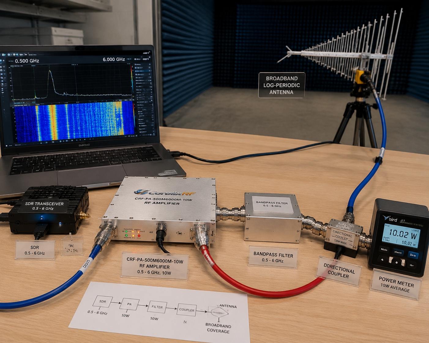
Not every broadband RF system needs hundreds of watts. Many engineering benches need a compact 0.5-6 GHz RF amplifier that can sit between a signal source and a device under test, extend SDR output power, support low-to-mid-power EMC work, or provide a controllable driver stage ahead of a larger amplifier. In those cases, size, flatness, control interface, and protection behavior can matter as much as headline power.
CorelixRF’s CRF-PA-500M6000M-10W is specified as a 0.5 GHz to 6 GHz GaN solid-state RF power amplifier with 10 W rated output power. The datasheet lists 40 dB minimum gain, -4 to +4 dB gain flatness, 0 dBm maximum input power, SMA-F input and output, CAN control, 28 V DC supply, 130 x 85 x 25 mm mechanical size, and system-level cooling. It also includes temperature and current monitoring, optional forward and reverse power monitoring, and protection functions for over-temperature, over-drive, over-voltage, and VSWR conditions.
Why a Compact 0.5-6 GHz Amplifier Is Useful
The 0.5-6 GHz range covers many lab and integration tasks where the RF source alone does not provide enough power. A compact broadband RF amplifier can support receiver testing, transceiver validation, antenna-path experiments, low-power interference simulation, and early-stage EMC work. It can also act as a driver when a larger final amplifier requires a controlled input level.
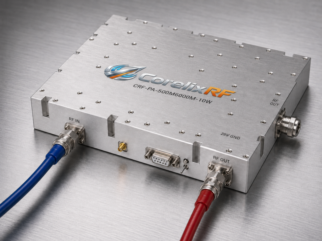
For SDR users, a low-power source may be flexible in frequency but limited in RF output. A 10 W amplifier gives the system more usable power while preserving broadband coverage. Engineers still need filtering and measurement discipline, but the amplifier can make the difference between a demonstration setup and a repeatable test chain.
Matching Source Level to Amplifier Gain
With 40 dB minimum gain and a 0 dBm maximum input level, the input chain needs care. A signal generator, SDR, or upconverter should not be connected directly at an unknown output level. The safer approach is to start with attenuation, verify drive power at the amplifier input, and then increase power under measurement.
This is especially important in automated benches. Scripts can set a source to the wrong level, call the wrong calibration table, or leave a previous test state active. A compact SDR RF amplifier should be protected by both hardware limits and software guardrails.
Gain Flatness and Calibration
The listed -4 to +4 dB gain flatness is reasonable for a broad 0.5-6 GHz module, but it still requires calibration when the test demands consistent delivered power. A lab should measure output power at representative frequencies, record cable and fixture losses, and build correction values into the procedure. This prevents the team from assuming that one input setting produces the same output from 500 MHz through 6 GHz.
For EMC and RF immunity support, delivered field strength or delivered RF power is usually more important than the amplifier’s nominal rating. Measurement should happen at the correct reference point in the system.
Mechanical and Control Integration
The 130 x 85 x 25 mm size makes this amplifier suitable for compact fixtures, embedded test platforms, and small rack subsystems. That does not mean cooling can be ignored. The datasheet references conduction or system-level cooling, so the mechanical design should include a heat path, mounting surface, airflow where needed, and temperature monitoring.
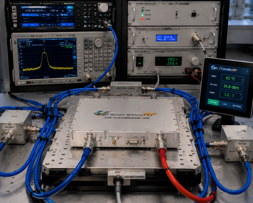
CAN control can be useful in embedded environments where multiple RF modules, sensors, and controller boards share a system bus. If the amplifier is being used in a larger custom RF amplifier assembly, the integrator should define command behavior, status reporting, fault latching, and recovery procedures during the design review.
When 10 W Is the Right Level
A 10 W broadband module is a good choice when the goal is controlled signal amplification rather than maximum RF field strength. It can support device characterization, small antenna testing, RF front-end stress tests, and driver-stage use. It may not be the right final amplifier for high-field EMC immunity or long cable runs with large loss, but it can be the correct building block inside those systems.
Lab Integration Notes
A practical 0.5-6 GHz setup should also define how the amplifier is powered on and off relative to the RF source. Many avoidable faults happen during sequencing, when the source is active before the load, attenuator, or cooling path is ready. For repeatable work, document a startup state, a maximum allowed drive level, and a shutdown state that removes RF drive before power is removed from the amplifier.
Practical RFQ Details
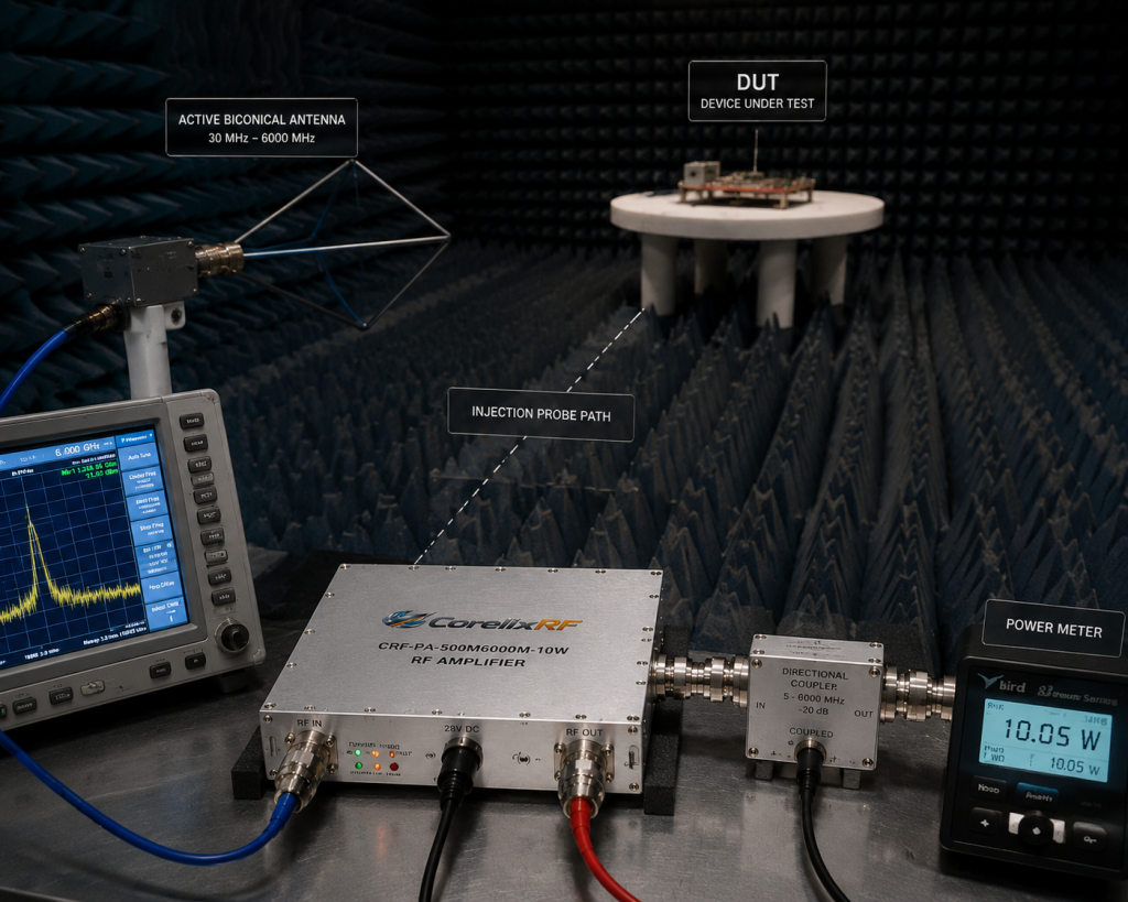
A clear RFQ should include the frequency range, expected output power at the load, waveform type, duty cycle, source type, input level range, connector requirements, control interface, cooling method, available DC power, and fault-handling expectations. If the amplifier is part of an SDR chain, include the SDR model, maximum output level, filtering plan, and whether the signal contains wideband modulation.
FAQ
Can a 0.5-6 GHz 10 W amplifier be used with SDR equipment?
Yes, if the SDR output level, filtering, impedance match, duty cycle, and input power limit are managed correctly.
Is this amplifier only for EMC work?
No. It can support EMC-related setups, communication testing, lab automation, receiver testing, and driver-stage applications.
Why does cooling matter for a small module?
Compact size concentrates heat. The final installation must provide a suitable conduction path or airflow so temperature protection does not become a routine operating limit.
What internal links should engineers review next?
Review CorelixRF’s EMC RF amplifiers, broader RF power amplifier options, and the SDR integration guide.