
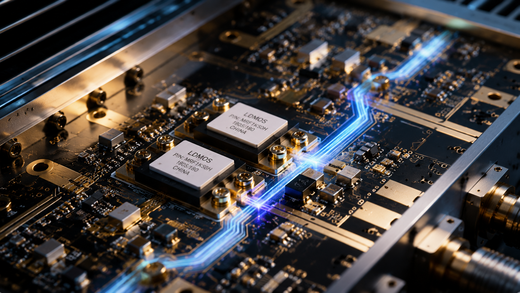
An 80 MHz to 1 GHz 500 W RF power amplifier is often selected when the test system must cover VHF, UHF, and lower L-band work with substantial RF power. This is a practical range for EMC immunity support, communication equipment testing, RF interference simulation, and wideband system verification. The amplifier must provide more than output power. It must handle mismatch risk, support repeatable gain behavior, fit rack-level thermal requirements, and provide control interfaces that operators can trust.
CorelixRF’s CRF-PA-80M1000M-500W is specified as an LDMOS solid-state RF power amplifier covering 80 MHz to 1 GHz with 500 W typical RF output power. The datasheet lists 57 dB minimum small-signal gain, -4 to +4 dB gain flatness, up to 20 dB gain control, 0 dBm maximum input power, N-Female input and output, LAN / RS485 control, AC 220 V supply, air cooling, and a 19-inch 4U rack-mount format. It also references real-time temperature and current monitoring, optional forward/reverse power monitoring, optional LAN remote monitoring, and protection for over-temperature, over-voltage, and over-drive conditions.
Why 80 MHz to 1 GHz Is a Demanding Band
This range is broad enough to include very different test conditions. Cable loss, antenna behavior, fixture response, and chamber coupling change significantly from 80 MHz to 1 GHz. A high-power EMC RF amplifier must therefore be evaluated as part of a system, not as a standalone box with a power number.
For EMC work, the delivered field strength depends on the amplifier, antenna, coupler, cable, chamber, and calibration method. For communication testing, the same amplifier may need to produce repeatable power into devices or subsystems with controlled mismatch. The 500 W level gives useful headroom, but it also increases the need for disciplined setup and protection.
LDMOS SSPA Strengths in This Range
LDMOS remains a practical technology for high-power lower-frequency RF amplification. In the CRF-PA-80M1000M-500W, the combination of 500 W output and 57 dB minimum gain means the system can reach high output levels from a low-power RF source. That gain is useful, but it also requires careful input limiting. The 0 dBm maximum input power should be treated as a hard design constraint.
A solid state power amplifier avoids many operational issues associated with tube-based systems, but it still needs correct load management, cooling, and operating procedures. Solid-state does not mean immune to reflected power or thermal stress.
Gain Flatness, Control, and Calibration
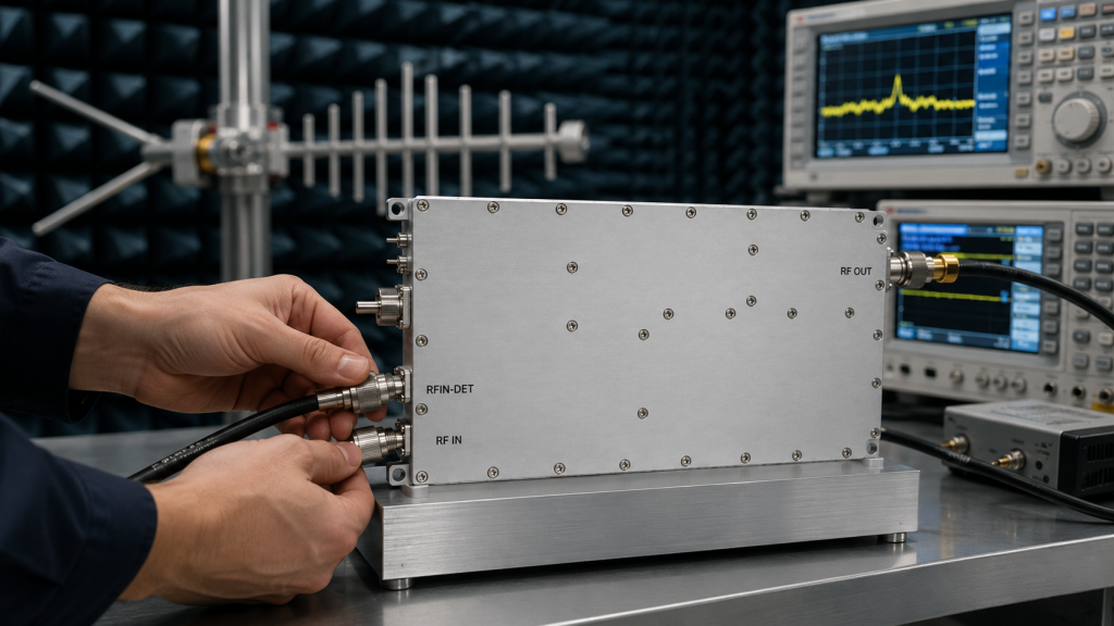
The -4 to +4 dB gain flatness specification is important for any swept-frequency test. In a frequency range this wide, even a few dB of variation can change delivered power enough to affect results. The 20 dB gain-control range helps operators or automation systems adjust output, but calibration should still be performed at the system reference plane.
For EMC immunity support, engineers should build a forward-power or field-strength table across the band. For communication testing, the team should define whether the amplifier is used in CW, modulated, pulsed, or intermittent operation and confirm that the waveform and duty cycle match the expected thermal load.
Rack, Cooling, and Remote Operation
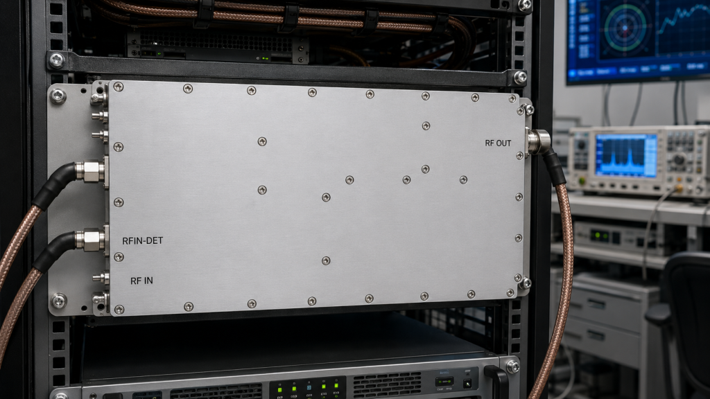
The 19-inch 4U rack-mount format makes this amplifier suitable for a fixed test system. Air cooling means the rack must provide intake clearance, exhaust clearance, and temperature control. In a busy lab, blocked air paths and poor cable routing are common causes of amplifier faults.
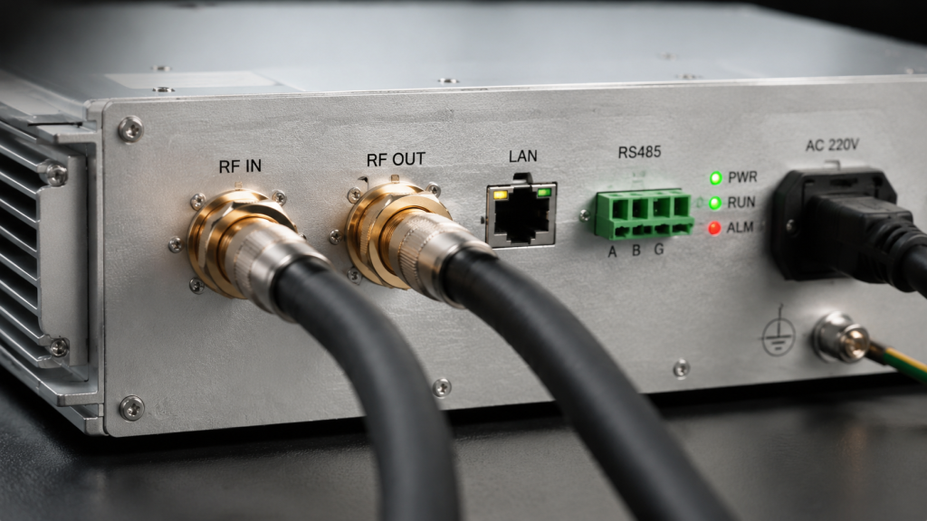
LAN and RS485 control are useful for automated systems. A remote interface can allow power sequencing, status monitoring, and fault logging. When integrating with a chamber, switch matrix, or safety interlock, the control strategy should define what happens after a reflected-power event, over-temperature alarm, or operator emergency stop.
Connector and Load Considerations
N-Female input and output are practical at this frequency range, but every part after the amplifier must be rated for power, frequency, and mismatch. Directional couplers, attenuators, loads, switches, and feedthroughs should be reviewed as a full RF path. If the amplifier feeds an antenna, the antenna VSWR across the operating range becomes part of the amplifier protection discussion.
Teams comparing broadband RF power amplifier options should ask for test data relevant to their required band, not just a single midpoint power value.
Safety and Operating Discipline
At 500 W, operating discipline is part of the specification. The test team should label high-power paths, verify terminations before applying drive, and prevent unattended operation until interlocks and monitoring have been validated. These steps protect equipment and also make test results easier to reproduce across shifts.
RFQ Checklist
Include the required frequency range, target output power at the load or antenna, modulation type, duty cycle, field-strength target if applicable, cable length, couplers, antenna type, operating environment, control interface, fault-handling behavior, and rack airflow constraints. If the system must meet a standard test method, specify the method and calibration process.
FAQ
Is 500 W always required for EMC testing?
No. The required amplifier power depends on field-strength target, antenna gain, chamber conditions, cable loss, and test distance. A 500 W amplifier is useful when the system needs margin across a wide band.
Why use LAN or RS485 control?
Remote control helps integrate the amplifier into automated test systems, chamber procedures, and fault logging workflows.
What is the biggest integration risk?
Mismatch and thermal stress are common risks. The output path, cooling, and operating procedures must be reviewed before high-power operation.
Can CorelixRF adapt this type of amplifier for a custom bench?
Project-specific review is appropriate when the bench has defined control, rack, cooling, or RF interface requirements.