
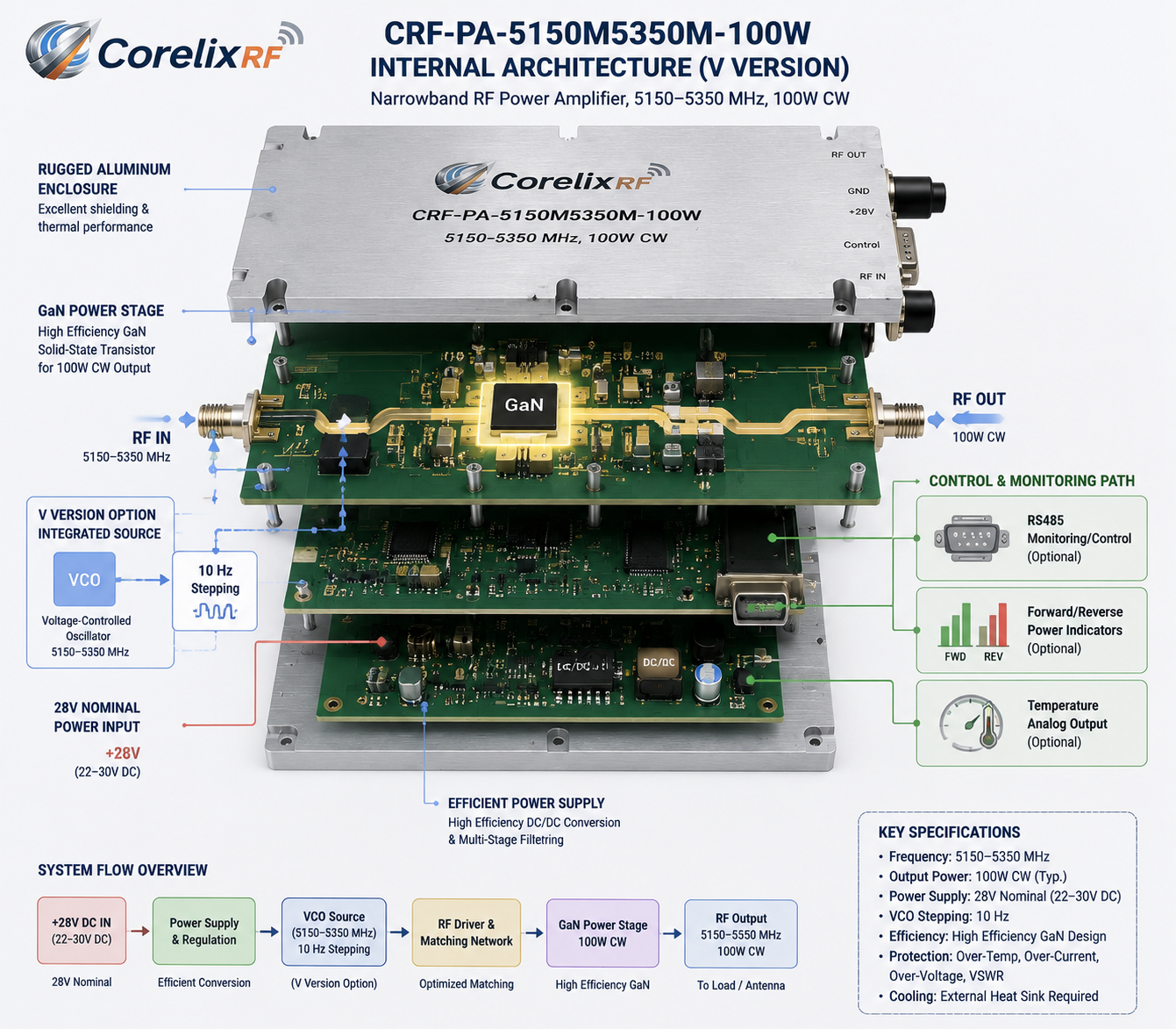
A 5150-5350 MHz 100 W narrowband RF power amplifier is a different engineering choice from a multi-octave broadband amplifier. It is selected when the system works inside a defined 5 GHz band and the priority is controlled CW output, compact integration, gain adjustment, and monitoring. For dedicated communication-channel testing, RF source integration, and narrowband equipment validation, a focused amplifier can be easier to package and operate than a broad 2-6 GHz or 1-6 GHz unit.
CorelixRF’s CRF-PA-5150M5350M-100W is specified as a GaN solid-state narrowband RF power amplifier covering 5150 MHz to 5350 MHz with 100 W rated CW output power. The datasheet lists 46 dB minimum gain, 48 dB typical gain, 50 dB maximum gain, 20 dB gain-adjustment range with 0.5 dB step, 24 to 32 V operating voltage, 28 V nominal supply, 16 A typical current, 20 A maximum current, SMA-KFD46 RF connectors, D-Sub 15-pin control/power interface, 160 x 120 x 25 mm mechanical size, 1.4 kg weight, and external heat-sink cooling. It also notes optional RS485 monitoring/control, PA enable/disable control, forward/reverse power indicators, temperature analog output, and protection functions for over-temperature, VSWR, voltage, and current faults.
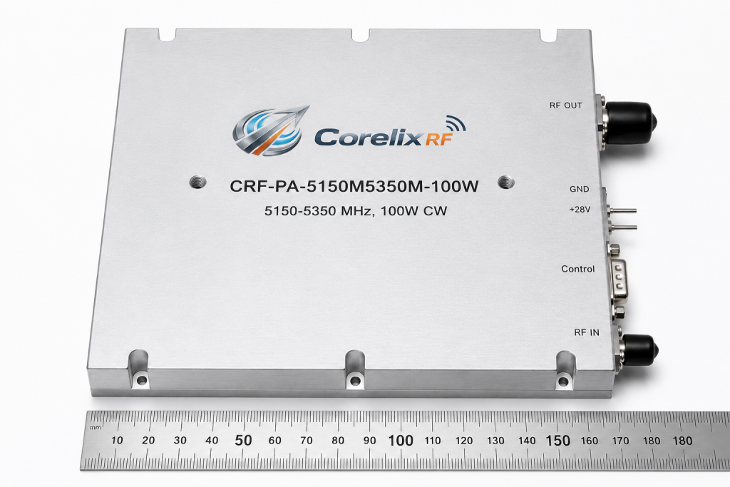
Why Choose Narrowband at 5 GHz
A narrowband RF amplifier can be the right choice when the frequency plan is stable. Instead of paying for bandwidth that the system will not use, the design can focus on the desired channel range, gain adjustment, thermal footprint, and control behavior. In the 5150-5350 MHz range, this can be useful for dedicated RF test channels, point-to-point communication experiments, source-integration projects, and subsystem validation.
The key is honesty about the required bandwidth. If the project may later need 2-6 GHz coverage, a broadband RF power amplifier may be a safer platform. If the operating band is fixed, the narrowband amplifier can simplify the mechanical and RF design.
Output Power and Gain Adjustment
The 100 W rated CW output power gives the system meaningful 5 GHz RF power in a compact module. The 46 to 50 dB gain range means the source can remain relatively low power, but input limiting and setup controls are still important. Gain adjustment in 0.5 dB steps is useful when the test procedure requires fine output control without large changes at the signal source.
Engineers should decide whether gain control is needed for calibration, production test, operator control, or closed-loop system behavior. That decision affects wiring, firmware, and user interface requirements.
M Version and V Version Planning
The datasheet notes configurations that include an M version without internal VCO and a V version with internal VCO source and 10 Hz stepping. This distinction matters. If the system already has a stable RF source, the M-style amplifier path may be appropriate. If the project needs an integrated RF source function, the V-style option may reduce external hardware, but it also changes frequency-control, phase-noise, and system-validation questions.
Before choosing between versions, define whether the amplifier is only a power stage or part of a complete RF source. That decision should be reviewed before mechanical packaging begins.
Thermal Design for a Compact 100 W Module
The 160 x 120 x 25 mm size is compact for a 100 W RF amplifier, but the module requires an external heat sink. That makes mechanical design central to performance. The heat sink, mounting pressure, thermal interface material, airflow, and operating temperature range should be specified. The datasheet lists -40 C to +60 C operation, but final performance depends on the system’s ability to remove heat.
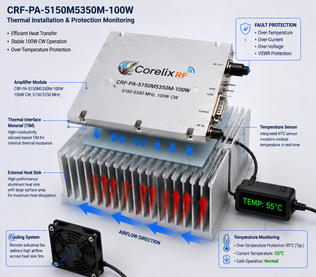
Protection functions such as over-temperature shutdown and recovery are valuable safeguards. They should not be used as normal temperature control. A well-designed custom RF amplifier assembly should keep the module within a stable thermal range during expected operation.
Monitoring, Protection, and Control
Optional RS485 monitoring/control, forward and reverse power indicators, and temperature analog output can help integrators build a safer RF system. The listed protection functions include over-temperature shutdown/recovery, over-VSWR locked shutdown, over-voltage lock above 32 V, and over-current lock above 22 A. These details should be included in the control logic and operator documentation.
For a production or automated bench, define what fault status is displayed, whether a fault requires manual reset, and how the system prevents immediate restart into the same load problem.
RFQ Checklist
A strong RFQ should specify the exact operating band, output power requirement, CW or modulated waveform, gain-control needs, M or V version preference, source characteristics, heat-sink design, supply voltage range, connector requirements, monitoring signals, RS485 needs, and expected mismatch environment. If the amplifier will be embedded, include board spacing, airflow, and grounding constraints.
FAQ
When is a 5150-5350 MHz amplifier better than a 1-6 GHz amplifier?
It is better when the project is fixed in this band and values compact size, focused gain behavior, and narrowband integration over wide frequency flexibility.
Does the module include its own heat sink?
The datasheet references external heat-sink cooling, so the final thermal solution must be designed into the system.
Why is 0.5 dB gain adjustment useful?
Fine gain steps help tune delivered power during calibration, production testing, or controlled RF source operation.
What should be confirmed before choosing the V version?
Confirm frequency-control needs, source purity requirements, stepping behavior, control interface, and how the integrated source will be validated.